1
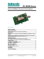
Radiocrafts Embedded Wireless Solutions RC-IESM-Series Radiocrafts IESM-Series Expansion Cards User Manual Table of contents TABLE OF CONTENTS ............................................................................................................ 1 QUICK START GUIDE .............................................................................................................. 2 PRODUCT DESCRIPTION........................................................................................................ 3 SUPPORTED PROTOCOLS AND NETWORK STANDARDS ................................................ 3 APPLICATIONS ........................................................................................................................ 3 FEATURES ................................................................................................................................ 3 FUNCTIONAL BLOCK DIAGRAM FOR WAVECOM MODEM AND RADIOCRAFTS IESM BOARDS.................................................................................................................................... 4 DEMONSTRATION FIRMWARE AND SOURCE CODE FOR THE WAVECOM MODEM ..... 4 WAVECOM MODEM EMBEDDED RESOURCES AND TOOLS ............................................. 4 FUNCTIONAL LAYOUT ............................................................................................................ 5 ANTENNA CONNECTION ........................................................................................................ 5 GPC, GENERAL PURPOSE CONNECTOR, PIN DESCRIPTION ........................................... 5 DATA FROM UART1 VIA UART2 FOR MODULE CONFIGURATION AND COMMUNICATION .................................................................................................................... 6 RC-IESM CIRCUIT DIAGRAM .................................................................................................. 9 RC-IESM PCB AND ASSEMBLY LAYOUT ............................................................................. 9 RC-IESM BILL OF MATERIALS ............................................................................................. 10 MECHANICAL DRAWING ...................................................................................................... 12 MECHANICAL DIMENSIONS ................................................................................................. 12 ARTICLE NUMBERS .............................................................................................................. 12 DOCUMENT REVISION HISTORY ......................................................................................... 13 DISCLAIMER ........................................................................................................................... 13 TRADEMARKS ....................................................................................................................... 13 LIFE SUPPORT POLICY ........................................................................................................ 13 CONTACT INFORMATION ..................................................................................................... 13 2009 Radiocrafts AS RC-IESM User Manual (rev. 1.0) Page 1 of 13 Radiocrafts Embedded Wireless Solutions RC-IESM-Series Quick Start Guide How do I set up a simple link between an IESM board and a matching Radiocrafts RF module? A basic communication test can be done by sending and receiving serial data via the external RS232 (UART1) on the Wavecom modem to and from a Radiocrafts Demonstration Board, after downloading the RTG-demonstration software into the modem and enabling serial-toserial mode: • • • • • • • Attach the antennas to the SMA connectors Download the latest version of RCTools from www.radiocrafts.com Install RCTools (this will also install the USB VCP (Virtual COM Port) driver) Connect the modem RS232 port, and the USB port on the Demo Board, to a PC Start a terminal program on the PC (like RC_CCT or Microsoft HyperTerminal). Make sure to select the correct serial port. Set Baud rate 19200, 1 start bit, no parity, 1 stop bit, no flow control for the Demo Board. Set Baud rate 115200,1 start bit, no parity, 1 stop bit, hardware flow control for the Wavecom modem Wavecom modem: Connect the battery eliminator plug to the DC jack. Put the battery eliminator in the wall outlet socket. Download the RTG-demonstration software into the modem and enable serial-to-serial mode For using RC2300-ZNM-IESM, change the UART2 setting to 115200 Baud and enable Hardware flow control, see the RTG User Manual. Other settings as above will meet the default settings of the RTG Software. The modules will now be in idle mode listening for a valid data packet to arrive. You can now enter data in one terminal window and after approximately 2 seconds timeout, the ASCII string is transmitted to the other module and shown in the other terminal window if the transmission was successful. For Wireless M-Bus and ZigBee (ZNM) the communication should be done via the RCTools named MBUS-DEMO and ZNM-CCT respectively. For a detailed description on how to find the right COM Port to use, and how to connect to, and use, the Demonstration Board, please see the RCxxxxDK-USB_User_Manual or RC2300DK-ZNM_Quick_Start available at www.radiocrafts.com. How do I go on and change the RF channel or any other parameter? To change configurable parameters on the Demonstration Board or IESM board, assert the CONFIG pin (pulling low), and send the command string using the same serial interface as for transmitting data. Parameters can be changed permanently and stored in non-volatile memory in the module. See following sections on how to enter configuration mode for the various IESM boards. NOTE! Always extract the IESM board from the modem by using an angled tool/hook inserted into the 3.2 mm hole in front of the IESM board. The GPC connector require a significant force to release its mating connector, thus never use other tools for extracting the IESM board as this may permanently damage the board. 2009 Radiocrafts AS RC-IESM User Manual (rev. 1.0) Page 2 of 13 Radiocrafts Embedded Wireless Solutions RC-IESM-Series Product Description The RC-IESM (Internal ExpanSion Module) series of expansion cards for the Wavecom Fastrack Supreme modems contains an RF module which interfaces to the UART serial bus inside the modem, and an SMA connector for the external antenna. The RF module is a Wireless M-Bus module, a ZigBee module, or any module from the RC232 protocol family from Radiocrafts. An embedded protocol inside the RF module handles all RF communication and only data payload and easy-to-use commands are sent over the UART serial bus. The PCB is the same for all modules which only requires different BOM (Bill of Material) to support the various protocols. The Wavecom Fastrack Supreme M2M modems contain a powerful microcontroller handling the GPRS/GMS/Edge communication and the serial communication towards the RF module. An Open AT demonstration software is available for download, enabling a fully working demonstration gateway to be established with minimum design effort. The software can be modified and tailored to fit numerous applications. Supported Protocols and Network Standards • Wireless M-Bus • IEEE 802.15.4 • ZigBee • 6LoWPAN • RC232 (proprietary) Applications GSM/GPRS/EDGE gateway solutions for: • AMR / Smart Metering • Home automation, building automation and industrial automation • Fleet and inventory management • Wireless sensor networks Features • GSM/GPRS/EDGE Gateway for Wireless M-Bus, ZigBee and RC232 • On-board radio module with embedded protocol • Easy-to-use UART interface connects to powerful Wavecom-internal ARM9 processor • RF interface with SMA connector connects to standard antennas • Same PCB supports modules from a large portfolio of RF modules • Miniature manual switch and LED (connects to ARM-processor) • Free open AT-command based demo software for socket connection and module configuration • CE certified • FCC pre-qualified for dedicated RF modules 2009 Radiocrafts AS RC-IESM User Manual (rev. 1.0) Page 3 of 13 Radiocrafts Embedded Wireless Solutions RC-IESM-Series Functional block diagram for Wavecom modem and Radiocrafts IESM boards Figure 1: Functional block diagram Demonstration firmware and source code for the Wavecom modem Demonstration software for enabling a socket connection for transparent GPRS payload transfer, and for enabling RF modem configuration, is available from Radiocrafts and Asvito, www.asvito.no. See the RTG User Manual for details on the RTG (Radio Test Gateway) software available for the Wavecom modem. Wavecom modem embedded resources and tools MCU: ARM9 32 bit, 26-104 MHz core IDE: Open AT IDE, Integrated Development Environment, where applications can be written, compiled, downloaded and monitored through the debugging phase of the development Software: Standard ANSI C, Open AT built on Eclipse, a fully integrated tool chain encompassing CDT, Terminal Emulator, Target Monitor, Compiler, Downloader and Supervisor 2009 Radiocrafts AS RC-IESM User Manual (rev. 1.0) Page 4 of 13 Radiocrafts Embedded Wireless Solutions RC-IESM-Series Functional Layout The ARM9 processor connects to the IESM board via a 50-pin GPC, General Purpose Connector, mounted on the secondary side of the board. The antenna connector is a standard SMA connector. Figure 2: IESM board functional connection Antenna connection A quarter wave antenna can be directly connected to the SMA antenna connector. If the modem is placed in environments where RF performance is reduced, an external antenna can be connected via an extension coaxial cable to the SMA connector. It is strongly recommended that the Wavecom GPRS antenna and the IESM antenna is not pointing in the same direction to reduce possible interference and range reductions; Thus, use angled GPRS antenna if straight antenna is used with the IESM card, and vice versa. GPC, General Purpose Connector, Pin Description Pin no 1-2 3-15 16 17-22 23 24 25 26 27-28 29 30 31 32 33 34 35 36-40 41 42 43-44 45 46-47 48-50 Pin name GND NC GPIO28 NC RXD2 TXD2 CTS2 RTS2 NC GPIO19 NC GPIO20 NC GPIO23 NC DTR1 NC VCC-2V8 GND NC GND 4V GND 2009 Radiocrafts AS Description and internal MCU connection System ground Not Connected Reset_N Not Connected Connects to the module’s RXD-pin Connects to the module’s TXD-pin Connects to the module’s CTS-pin Connects to the module’s RTS-pin Not Connected Push Button Not Connected LED (green) Not Connected Config (enable module configuration mode) Not Connected Pull-up to pin 41 Not Connected Used for board-internal pull-up System ground Not Connected System ground Connected to modules VCC pin via on-board Low Dropout Regulator System ground RC-IESM User Manual (rev. 1.0) Page 5 of 13 Radiocrafts Embedded Wireless Solutions RC-IESM-Series Data from UART1 via UART2 for module configuration and communication For detailed instructions on how to handle I/O’s on the GPC connector and for changing UART1 and UART2 Baud rates and handshake, see the RTG User Manual. Common to all IESM-boards: - UART2 default settings are 19200 Baud, no parity, 1 start and stop bit, no handshake. These are also the default settings for all IESM boards except RC2300ZNM-IESM, thus no modification of UART2 settings is required. For using RC2300ZNM-IESM, see below. 1. Connect a HyperTerminal window to UART1 as described in the Quick Start section 2. Switch off hardware handshake on UART2 via AT+IPC=0,0 3. Release the COM-port RC232 protocol modules See the related document RC232-CCT User Manual for a detailed description on how to use the RCtool for configuration and communication with the module with the embedded RC232 protocol. Follow 1-3 above, then; - Start the CCT program - Connect to the correct COM-port (normally COM1, RS232-port) - Wireless communication to another module (or module on a Demo Board) can directly be done by entering text strings at the Terminal Line - Enter transparent UART-UART mode via sending AT+MODE=2 in the Terminal Line, tick for CR+LF - To enter configuration mode for the module, place the text AT+GPIO=1,0,4 in the Terminal Line. Tick for CR+LF and send the text with the right-pointing arrow - Press the configure button in CCT; The program now displays “waiting for prompt sign (..)” - Go to the arrow to the right of the Terminal Line and send a single character ‘Y’ - The module has entered configuration mode and now responds with the prompt, making it possible to read back data and change requested locations - Change parameters as described in the CCT User Manual - After exiting configuration mode and before being able to communicate in transparent mode, write +++ and wait for response followed by AT+GPIO=1,1,4 in the Terminal Line to set the Config-pin high Terminal Line Figure 3: RC232-CCT Window 2009 Radiocrafts AS RC-IESM User Manual (rev. 1.0) Page 6 of 13 Radiocrafts Embedded Wireless Solutions RC-IESM-Series MBUS protocol modules See the related document MBUS-CCT User Manual for a detailed description on how to use the RCtool for configuration and communication with the module with the embedded Wireless M-Bus protocol. Follow 1-3 on previous page, then; - Start the CCT program - Connect to the correct COM-port - Wireless communication to another module (or module on a Demo Board) can directly be done by entering text strings in the Terminal Line. Remember that first byte in transmission has to be string length byte (including length byte itself) - Enter transparent UART-UART mode via sending AT+MODE=2 in the Terminal Line, tick for CR+LF - Press the configure button, the module now enters configuration mode - Change parameters as described in the CCT User Manual - The CCT-program handles all UART instructions required to enter and leave configuration mode and entering terminal mode Terminal Window Figure 4: MBUS-CCT Window 2009 Radiocrafts AS RC-IESM User Manual (rev. 1.0) Page 7 of 13 Radiocrafts Embedded Wireless Solutions RC-IESM-Series ZNM protocol modules. See the related document RC2300-ZNM Demonstration Kit Quick Start (including ZNM-CCT User Manual) for a detailed description on how to use the RCtool for configuration and communication with the module with the embedded ZNM protocol. - Connect to correct COM-port via HyperTerminal using same settings as in Quick Start section - Set UART1 to ZNM default settings, 115200 baud and hardware handshake, via command AT+MSER=115200,1 - Restart modem via command AT+CFUN=1 - Disconnect HyperTerminal and connect ZNM-CCT to the same COM-port Figure 5: ZNM Window 2009 Radiocrafts AS RC-IESM User Manual (rev. 1.0) Page 8 of 13 Radiocrafts Embedded Wireless Solutions RC-IESM-Series RC-IESM Circuit Diagram The circuit diagram of the RC-IESM board is shown in figure 6. A full resolution schematic is found in RC_IESM_2_0.zip available from Radiocrafts’ webpage. Figure 6: RC-IESM Circuit diagram RC-IESM PCB and Assembly layout The PCB is a simple 2-layer board where Layer 2 is used as ground plane. The laminate used is standard FR-4 board material. The PCB is 1.0 mm thick. Full resolution layout and assembly drawing are found in RC_IESM_2_0.zip. Figure 7: RC-IESM PCB component placement, top side 2009 Radiocrafts AS RC-IESM User Manual (rev. 1.0) Page 9 of 13 Radiocrafts Embedded Wireless Solutions RC-IESM-Series RC-IESM Bill of Materials The circuit diagram includes all components of the RC-IESM. Note that RC11xx, RC12x0/2x00 and RC2300 all requires different component mounting. Details are listed in the following tables. Components not to be mounted are marked DNM (Do Not Mount) in the ‘Quantity’ column. Reference L1 Q1-5 Quantity 1 5 P3 P8 C5;C10 C3 C4 FM1-6 H1 H2 D1 U3 S1 M3 P4 U4 R47;R56 R29 R2;R4-5;R911;R42;R4546;R48 R1420;R24;R3035;R39;R5055;R57;R59 R21-23;R2528;R38;R4041;R44;R49; R58 1 1 (DNM) 2 1 1 6 (DNM) 1 (DNM) 1 (DNM) 1 1 1 1 1 1 2 1 10 23 (DNM) 2009 Radiocrafts AS 13 RC-IESM Bill of materials for RC11xx Part number Description BLM11A102S EMI filter bead BSS138 MOSFET, N, 50V, 1.6V threshold CONN_WAVECOM_IES M_50PIN 50-pin connector, plug, 0.5 mm pitch CON_2X7_TH_MALE_ HOUSE Connector 14 pins, pin header in house C_100P_0603_NP0_J_50 Capacitor, 0603 C_2U2_0603_X5R_K_10 Capacitor, 0603 C_3U3_TAN_B Capacitor, tantal FIDUCIAL_MARK Fiducial mark HOLE_1.0_PTH Hole, 1.0mm, PTH HOLE_3.2_NPTH Hole, NPTH LED_0603_RA_GREEN LED, 0603 size Right Angle, green LP2980-3.0V 3.0V low drop-out regulator PUSH_BUTTON_RA Push button, SMD, Right angled RC1XX0_230X_COMBO Radiocrafts RF Module SMA_SMD_CENTERED SMA connector, Right Angle, PCB centred TPS3809J25 Voltage supervisor, 2.5V, SOT-23 R_1K0_0603_J Resistor, 0603 R_220_0603_J Resistor, 0603 R_8K2_0603_G Resistor, 0603 R_0603 Resistor, 0603, general R_0_0603 Resistor, 0603 RC-IESM User Manual (rev. 1.0) Page 10 of 13 Radiocrafts Embedded Wireless Solutions RC-IESM-Series RC-IESM Bill of materials for RC10xx, RC12xx and RC2x00 Reference Quantity Part number Description Same components as for RC11xx except for components R_0603 (DNM) and R_0_0603 (0-ohm) R15Resistor, 0603, general 23 R_0603 17;R23;R25(DNM) 28;R3035;R39;R41; R5054;R57;R59 R14;R18Resistor, 0603 12 R_0_0603 22;R24;R38; R40;R44; R49;R58 RC-IESM Bill of materials for RC2300 Reference Quantity Part number Description Same components as for RC11xx except for components R_0603 (DNM) and R_0_0603 (0-ohm) R14-16;R18Resistor, 0603, general 19 R_0603 20;R23(DNM) 26;R39;R4950;R5255;R57-58 R17;R21Resistor, 0603 17 R_0_0603 22;R2728;R3035;R38;R4041;R44;R51; R59 2009 Radiocrafts AS RC-IESM User Manual (rev. 1.0) Page 11 of 13 Radiocrafts Embedded Wireless Solutions RC-IESM-Series Mechanical Drawing Figure 8: Mechanical drawing Mechanical Dimensions The board size is 35.7 x 57.0 x 4.1 mm (total height for PCB and module). ZigBee is a registered trademark of the ZigBee Alliance. © 2008 Radiocrafts AS. All rights reserved. Article Numbers Ordering Number RC1180-MBUS-IESM RC2300-ZNM-IESM RC1140-RC232-IESM RC1180-RC232-IESM RC1190-RC232-IESM RC1240-RC232-IESM RC1280-RC232-IESM RC1290-RC232-IESM Module Desription Embedded Wireless M-Bus protocol (EN13757-4:2005, 868 MHz radio) for gas, water, heat and electricity meter readings ZigBee Network Module 433, 868 and 915 MHz high speed modules, RC232 protocol 433, 868 and 915 MHz narrowband long range, RC232 protocol Visit www.radiocrafts.com for product description of each module. 2009 Radiocrafts AS RC-IESM User Manual (rev. 1.0) Page 12 of 13 Radiocrafts Embedded Wireless Solutions Document Revision History Document Revision 1.0 RC-IESM-Series Changes First release Disclaimer Radiocrafts AS believes the information contained herein is correct and accurate at the time of this printing. However, Radiocrafts AS reserves the right to make changes to this product without notice. Radiocrafts AS does not assume any responsibility for the use of the described product; neither does it convey any license under its patent rights, or the rights of others. The latest updates are available at the Radiocrafts website or by contacting Radiocrafts directly. As far as possible, major changes of product specifications and functionality, will be stated in product specific Errata Notes published at the Radiocrafts website. Customers are encouraged to check regularly for the most recent updates on products and support tools. Trademarks RC232™ is a trademark of Radiocrafts AS. The RC232™ Embedded RF Protocol is used in a range of products from Radiocrafts. The protocol handles host communication, data buffering, error check, addressing and broadcasting. It supports point-to-point, point-to-multipoint and peer-to-peer network topologies. All other trademarks, registered trademarks and product names are the sole property of their respective owners. Life Support Policy This Radiocrafts product is not designed for use in life support appliances, devices, or other systems where malfunction can reasonably be expected to result in significant personal injury to the user, or as a critical component in any life support device or system whose failure to perform can be reasonably expected to cause the failure of the life support device or system, or to affect its safety or effectiveness. Radiocrafts AS customers using or selling these products for use in such applications do so at their own risk and agree to fully indemnify Radiocrafts AS for any damages resulting from any improper use or sale. © 2009, Radiocrafts AS. All rights reserved. Contact Information Web site: www.radiocrafts.com Address: Radiocrafts AS Sandakerveien 64 NO-0484 OSLO NORWAY Tel: +47 4000 5195 Fax: +47 22 71 29 15 E-mails: [email protected] [email protected] [email protected] 2009 Radiocrafts AS RC-IESM User Manual (rev. 1.0) Page 13 of 13