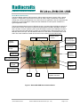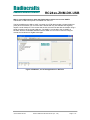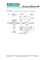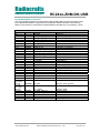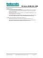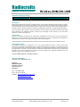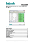
1
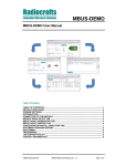
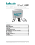
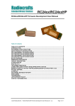
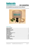
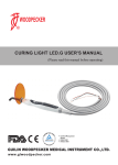
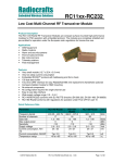
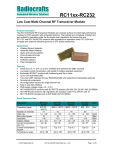
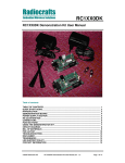
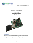
Radiocrafts
Embedded Wireless Solutions
RC24xx-ZNM-DK-USB
RC24xx-ZNM-DK-USB Demonstration Kit User Manual
Table of contents
TABLE OF CONTENTS............................................................................................................ 1
DEMONSTRATION KIT INTRODUCTION ............................................................................... 2
DEMO BOARD INTRODUCTION ............................................................................................. 3
BLOCK DIAGRAM.................................................................................................................... 5
JUMPER SECTION................................................................................................................... 6
PROTOTYPING WITH THE RCXXXXDB-USB ........................................................................ 8
ANTENNA SELECTION VERSUS RANGE PERFORMANCE ................................................ 8
RCXXXXDB-USB CIRCUIT DIAGRAM .................................................................................... 9
RCXXXXDB-USB PCB AND ASSEMBLY LAYOUT ............................................................... 9
RCXXXXDB-USB BILL OF MATERIALS............................................................................... 10
TROUBLESHOOTING ............................................................................................................ 11
DOCUMENT REVISION HISTORY......................................................................................... 12
DISCLAIMER .......................................................................................................................... 12
TRADEMARKS ....................................................................................................................... 12
LIFE SUPPORT POLICY ........................................................................................................ 12
CONTACT INFORMATION..................................................................................................... 12
©2010 Radiocrafts AS
RC24xx-ZNM-DK-USB User Manual (rev. 1.00)
Page 1 of 12
Radiocrafts
Embedded Wireless Solutions
RC24xx-ZNM-DK-USB
Demonstration kit Introduction
The Demonstration Kit (DK) is designed to make it easy for the user to evaluate the onboard
module, develop an application and build prototypes very quickly. The kit includes three
Demo Boards (DB). The demo board contains the selected module with its dedicated article
number and embedded protocol and associated support circuits. The board can easily be
operated using a PC terminal emulator or the RCTools PC suite from Radiocrafts.
Your Demonstration Kit should contain the following items:
Kit contents
Item
Demo board w/radio module
Antenna, 50Ω quarter-wave monopole, SMA male connector
USB Cable
CC-debugger
Number of articles
3
3
3
1
This User Manual describes how to use the Demonstration Kit and provides detailed
documentation for the Demonstration Board.
The Demonstration Kit includes what you need to evaluate the RF performance of the
modules, develop your own application interfacing the modules, and can also be used to build
a prototype of your application.
Related document also required to use the kit
- RC2400/RC2400HP-ZMN-DK-USB Quick Start
- ZNM-CCT User Manual
- RC2400/RC2400HP-ZNM User Manual
©2010 Radiocrafts AS
RC24xx-ZNM-DK-USB User Manual (rev. 1.00)
Page 2 of 12
Radiocrafts
Embedded Wireless Solutions
RC24xx-ZNM-DK-USB
Demo Board Introduction
The Demo Board contains USB connector, USB to serial converter, buttons, LEDs, voltage
regulator, configuration jumpers and connectors to make it easy to interface the onboard
module with various test equipment or the host used in an application. Not all components are
needed in an actual application. Please see the datasheet for each specific module for a
typical application circuit.
The Demonstration Board comes in different versions, equipped with the different variants of
Radiocrafts modules. Among the frequencies supported are 433 MHz, 868 MHz, 915 MHz
and 2.45 GHz. For each frequency there exist narrowband versions and wideband versions.
This covers the most used frequency bands, the 433 MHz band in Europe and the US, the
868 MHz band in Europe, the 902-928 MHz band in the US and the 2 450 MHz band worldwide. The actual module mounted can be seen on the marking on the module itself.
LEDs
Buttons, S3-S5
Module article
number
P9: Module
Power jumper
Voltage
regulator
P1: UART I/O
level jumper
P3: USB LED
jumper
P4:
Antenna
connector
USB LED
P2: USB connector
RESET
P10: CTS
Jumper
CONFIG
P13: Digital
I/O connector
S1
S2
P8: Module Firmware
update connector
Figure 1: RCxxxxDB-USB Demonstration Board
©2010 Radiocrafts AS
RC24xx-ZNM-DK-USB User Manual (rev. 1.00)
Page 3 of 12
Radiocrafts
Embedded Wireless Solutions
RC24xx-ZNM-DK-USB
Why is it an USB connector when the Radiocrafts modules use a serial UART?
The benefit of USB is that power is available from the Port.
The RCxxxxDB has an USB to UART converter from FTDI that includes a Virtual COM Port
(VCP) driver that allows you to use the demo boards with any PC software that originally
require a serial COM port. This means that the PC will communicate with the module using a
serial connection via the virtual COM port. The UART is connected to the P0 UART on
RC2400. With the embedded ZNM firmware the ZNM-CCT tool can be used to configure
module and send/receive ZigBee messages.
Figure 2: ZNM-CCT, one of the applications in RCTools
©2010 Radiocrafts AS
RC24xx-ZNM-DK-USB User Manual (rev. 1.00)
Page 4 of 12
Radiocrafts
Embedded Wireless Solutions
RC24xx-ZNM-DK-USB
Block Diagram
The block diagrams in figure 3 informs about actual parts used for a given demo board.
Figure 3 RC24xxDB-USB
©2010 Radiocrafts AS
RC24xx-ZNM-DK-USB User Manual (rev. 1.00)
Page 5 of 12
Radiocrafts
Embedded Wireless Solutions
RC24xx-ZNM-DK-USB
Jumper section
The board contains several jumper options for connector P1, P3, P9, P10 and P13. The
connectors and jumper settings are summarized in this chapter.
Pin
#
1
2
Signal
RC_VCC
VCCIO_FT232
3
Module Power. Connect to pin 2 during default.
Sets the UART voltage level for the USB chip and provide power to the
USB LED. Must not exceed more than RC_VCC+0.3V.
Remove jumper when measuring SLEEP and OFF current in order not
to include leakage current from the USB chip UART.
3.3V regulator output from USB chip. Connect to pin 2 when measuring
current consumption in RX and TX mode.
3V3
Pin #
Signal
1
2
TXD Data
3
4
RXD data
5
6
POWER
Pin
#
P1: UART voltage level jumper
Note
Signal
P3: USB LED Jumper
Note
Install jumper to enable LED blink when data on UART RXD. RF
transmit mode
Install jumper to enable LED blink when data on UART TXD. RF receive
mode
Install jumper to enable LED when Power is available from USB
(default). LED current draw is typ 2.5 - 3.5 mA depending on RF
module
P9: Module Power jumper
Note
1
GND
2
RCxxxx pin12
3
RCxxxx pin11
4
VCC_REGOUT
5
RC_VCC
6
7
RC_BATTERY
VCC_REGIN
RC11xx/RC2xxxDB-USB: RESET (not in use)
RC12xxDB-USB: ON/OFF. Connect to pin 1 to measure OFF current
drain. Note that The 100k pull-up resistor R2 will draw approximately 27
uA in OFF mode if not removed. The pull-up resistor is used to keep the
module in ON mode for normal use. In a real application this pin could
be controlled by a digital output, and (the pull-up) R2 could be omitted,
and hence the very low OFF mode current consumption can be achieved
RC11xx/RC2xxxDB-USB: not in use
RC12xxDB-USB: VDD (internal regulator out from the module)
RC11xxDB-USB: Power from external regulator (3.0V)
RC2xxxDB-USB: Power from external regulator (3.3V)
RC12xxDB-USB: USB chip regulator (3.3V)
Power to the module. An ampere meter can be connected in order to
measure the DC current drawn by the module. External power can also
be connected to this pin. Ensure that the same level is connected to P1
pin 2.
Power from battery on the bottom side
Input to external regulator
8
VBUS
Power from USB port
©2010 Radiocrafts AS
RC24xx-ZNM-DK-USB User Manual (rev. 1.00)
Page 6 of 12
Radiocrafts
Embedded Wireless Solutions
RC24xx-ZNM-DK-USB
As described in the table above, the RC11xx/RC2xxxDB-USB series has a different
component assembly compared to the RC12xxDB-USB for P9. Connector and default jumper
settings are illustrated below for the two different assemblies.
P9 jumper for RC11xx/RC2xxxDB-USB
P9 jumpers for RC12xxDB-USB
Figure 4: RCxxxxDB-USB P9 assembly and default jumper settings
P10: CTS
Pin #
1
2
Pin #
Signal
CTS
Signal
Note
Remove jumper for enabling CTS for RC12xxDB-USB. Not in use for
RC11xx/RC2xxxDB-USB
P13: Digital I/O Connector
Note
1
2
GND
3
4
RTS
RC11xx/RC2xxxDB-USB: Connect jumper between 2 and 4 to enter
sleep mode
Install jumper when using hardware handshake
5
6
CTS
Install jumper when using hardware handshake
7
8
CONFIG
9
10
TXD
11
12
RXD
7 and 8 connected together. Connect pin 7 to pin 3 for PC control of
CONFIG
Jumper installed from factory
RC11xx/RC2xxxDB-USB: Remove jumper when measuring sleep mode
current
Jumper installed from factory
RC11xx/RC2xxxDB-USB: Remove jumper when measuring sleep mode
current
13
14
GND
©2010 Radiocrafts AS
RC24xx-ZNM-DK-USB User Manual (rev. 1.00)
Page 7 of 12
Radiocrafts
Embedded Wireless Solutions
RC24xx-ZNM-DK-USB
Prototyping with the RCxxxxDB-USB
All pins to the module are available though standard pin rows using a pitch distance of 100 mil
(2.54 mm). This simplifies the build of a standalone application just by making a small plug-inboard to the existing Demo Board. Battery connectors on the bottom side are available for self
powered demos, and there is also access to VBUS (+5V), REGIN and REGOUT on P9. The
Battery clips and most of the connectors are not mounted from factory, but part numbers are
available from the Bill of Materials at the end of this document. The idea is that an external
MCU and application specific sensors etc easily can be connected to the Demo Board as a
proof of concept for the final product.
Antenna selection versus range performance
The choice of antenna is crucial for achieving the maximum range for any radio system. Due
to the small size of the PCB and the off-centre placement of the onboard SMA connector the
Demo Boards will not demonstrate the maximum range or omnidirectional radiation. To
improve this, a larger groundplane and a centred placement of the antenna above this
groundplane is required. One possible solution for maximum radiation is shown in the figure
below. With the addition of two different SMA adaptors and one sufficiently large groundplane
(radius ≥ L, length of the antenna) and a good electrical connection to the GND-layer, an
optimum performance of the antenna following the kit is achieved.
Other antenna solutions can be tested by connecting to the existing SMA female connector
on the Demo Board via one of the methods below:
1. Solder the feeding point of the antenna to be tested directly to an SMA male
connector and fasten to the SMA female connector
2. Connect to an external antenna (or board with antenna) via a shortest possible 50
Ohm coax cable with minimum insertion loss
Antenna
Antenna length L
Minimum radius of
GND plane = L
PCB with solid bottom
GND layer
SMA female/female
adaptor in drilled
hole
SMA male/male
adaptor
Radiocrafts Demo
Board
Proper connection
betwen GND plane
and adaptor outer
shielding
Figure 5: Extending size of ground plane with extra PCB
©2010 Radiocrafts AS
RC24xx-ZNM-DK-USB User Manual (rev. 1.00)
Page 8 of 12
Radiocrafts
Embedded Wireless Solutions
RC24xx-ZNM-DK-USB
RCxxxxDB-USB Circuit Diagram
The circuit diagram of RCxxxxDB-USB is in figure 8. A full resolution schematic is found in
RCxxxxDB_x_x.zip available from Radiocrafts’ webpage.
Figure 6: RCxxxxDB-USB Circuit diagram
RCxxxxDB-USB PCB and Assembly layout
The PCB is a simple 4-layer board where Layer 2 is used as ground plane. The laminate used
is standard FR-4 board material. The PCB is 1.6mm thick. Full resolution layout and assembly
drawing are found in RCxxxxDB-USB_x_x.zip.
Figure 7: RCxxxxDB-USB PCB component placement, top side
©2010 Radiocrafts AS
RC24xx-ZNM-DK-USB User Manual (rev. 1.00)
Page 9 of 12
Radiocrafts
Embedded Wireless Solutions
RC24xx-ZNM-DK-USB
RCxxxxDB-USB Bill of materials
The circuit diagram includes all components of RCxxxxDB-USB, but all three versions of the
Demo Boards has different component bill of materials. Details are listed in the following
tables. Components not mounted are marked DNM (Do Not Mount) in the ‘Quantity’ column.
Reference
D4
P3
P13
P8
P10
P1; P9
P5
P6-7;
C3-4
C5
C1;C6
C2
B1-4
FM1-3
U1
H5-8
D1
D3
D2
U2
L1
S1-2
S3-7
M1
R4;
R13-R22;
R30-32
R1; R5;
R11;R12;
R23-27;
R3; R10
R2;R28-29
P4
U3
P2
RCxxxxDB-USB Bill of materials for RC24xx-ZNM-DB-USB
Quantity
Part number
Description
1
BAT254
Diode, Si
1
CON_2X3_TH_MALE
Connector 6 pins, pin header
1
CON_2X7_TH_MALE
Connector 14 pins, pin header
1
CON_2X5_TH_MALE
Connector 10 pins
1(DNM)
CON_2_TH_MALE
Connector, 0.9 mm pin, male
2
CON_3
Connector, 0.9 mm pin
1(DNM)
CON_7_TH
Connector, 0.9 mm pin
2(DNM)
CON_8_TH
Connector, 0.9 mm pin
2
C_100N_0603_X7R_K_50 Capacitor, 0603
1
C_10N_0603_X7R_K_50
Capacitor, 0603
2
C_2U2_0603_X5R_K_10
Capacitor, 0603
1
C_3U3_TAN_B
Capacitor, tantalum
4(DNM)
ClipR03
Battery ClipR03 (AAA)
3(DNM)
FIDUCIAL_MARK
Fiducial mark
1
FT232RQ
USB UART IC
4
HOLE_4.2
PCB feet
1
LED_CL150DCD
LED, orange, SMD
1
LED_CL150GCD
LED, green, SMD
1
LED_CL150YCD
LED, yellow, SMD
1
LP2992-3.3V
3.3V low drop-out regulator. 250 mA
1
L_BEAD_102_0603
EMI filter bead
2(DNM)
PUSH_BUTTON
Push button, SMD
5
PUSH_BUTTON
Push button, SMD
1
RC24XX-ZNM
RF Module
14(DNM)
R_0603
Resistor, 0603, general
9
2(DNM)
3
1
1(DNM)
1
R_0_0603
R_100K_0603_G
R_270_0603_J
SMA
TPS3809J25
USB_B
Resistor, 0603
Resistor, 0603
Resistor, 0603
SMA connector
Voltage supervisor, 2.5V, SOT-23
USB B-style connector
©2010 Radiocrafts AS
RC24xx-ZNM-DK-USB User Manual (rev. 1.00)
Page 10 of 12
Radiocrafts
Embedded Wireless Solutions
RC24xx-ZNM-DK-USB
Troubleshooting
It doesn’t work. The Power LED is not lighting.
• Is the USB connector active? Some USB ports may be disabled if it’s not commonly
in use. The Demo board takes power from the USB port, and need an active USB
port to power the board.
•
Are all jumpers placed at the default position? P3 can disable POWER LED info, and
P9 can disable power to the module.
•
Is the module powered correctly? Measure the supply voltage at P9, pin 5. Should be
3.0V for RC11xxDB-USB and 3.3V for RC12xxDB-USB and RC2xxxDB-USB
I cannot communicate with the UART through the serial port
• Make sure that the RXD, TXD, RTS and CTS jumpers are inserted on P13.
•
Set up your terminal program according to the instructions in the Quick Start Guide.
Remember to select the correct COM-port and connect to this port.
©2010 Radiocrafts AS
RC24xx-ZNM-DK-USB User Manual (rev. 1.00)
Page 11 of 12
Radiocrafts
Embedded Wireless Solutions
Document Revision History
Document Revision
1.0
RC24xx-ZNM-DK-USB
Changes
First release for RC2400/RC2400HP
Disclaimer
Radiocrafts AS believes the information contained herein is correct and accurate at the time of this printing. However,
Radiocrafts AS reserves the right to make changes to this product without notice. Radiocrafts AS does not assume
any responsibility for the use of the described product; neither does it convey any license under its patent rights, or
the rights of others. The latest updates are available at the Radiocrafts website or by contacting Radiocrafts directly.
As far as possible, major changes of product specifications and functionality, will be stated in product specific Errata
Notes published at the Radiocrafts website. Customers are encouraged to check regularly for the most recent
updates on products and support tools.
Trademarks
RC232™ is a trademark of Radiocrafts AS. The RC232™ Embedded RF Protocol is used in a range of products from
Radiocrafts. The protocol handles host communication, data buffering, error check, addressing and broadcasting. It
supports point-to-point, point-to-multipoint and peer-to-peer network topologies.
All other trademarks, registered trademarks and product names are the sole property of their respective owners.
Life Support Policy
This Radiocrafts product is not designed for use in life support appliances, devices, or other systems where
malfunction can reasonably be expected to result in significant personal injury to the user, or as a critical component
in any life support device or system whose failure to perform can be reasonably expected to cause the failure of the
life support device or system, or to affect its safety or effectiveness. Radiocrafts AS customers using or selling these
products for use in such applications do so at their own risk and agree to fully indemnify Radiocrafts AS for any
damages resulting from any improper use or sale.
© 2010, Radiocrafts AS. All rights reserved.
Contact Information
Web site: www.radiocrafts.com
Address:
Radiocrafts AS
Sandakerveien 64
NO-0484 OSLO
NORWAY
Tel: +47 4000 5195
Fax: +47 22 71 29 15
E-mails: [email protected]
[email protected]
[email protected]
©2010 Radiocrafts AS
RC24xx-ZNM-DK-USB User Manual (rev. 1.00)
Page 12 of 12