1
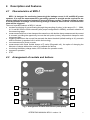
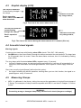
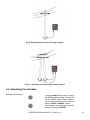
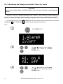
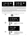
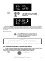
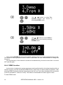
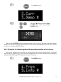
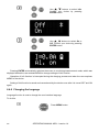
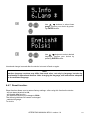
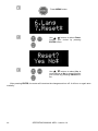
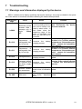
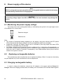
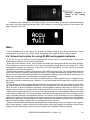
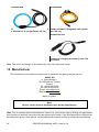
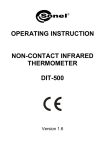
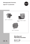
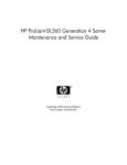
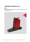
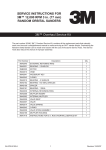
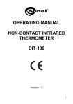
OPERATING MANUAL MPU-1 LEAKAGE CURRENT ALARM SIGNALLER SONEL SA ul. Wokulskiego 11 58-100 Świdnica, Poland Version 1.4 10.10.2014 2 OPERATING MANUAL MPU-1 version 1.4 CONTENTS 1 PREFACE ................................................................................................................ 5 2 INTRODUCTION ................................................................................................... 6 3 SAFETY ................................................................................................................... 6 4 DESCRIPTION AND FEATURES ....................................................................... 7 4.1 CHARACTERISTICS OF MPU-1................................................................................. 7 4.2 ARRANGEMENT OF SOCKETS AND BUTTONS ............................................................ 7 4.2.1 Keyboard ...................................................................................................... 8 4.2.2 Sockets .......................................................................................................... 9 4.3 GRAPHIC DISPLAY (LCD) ..................................................................................... 10 4.4 ACOUSTIC/VISUAL SIGNALS. ................................................................................. 10 4.5 MEASURING CLAMPS ............................................................................................ 10 5 STARTING THE OPERATION .......................................................................... 11 6 OPERATION ......................................................................................................... 11 6.1 PREPARING MPU-1 FOR OPERATION ..................................................................... 11 6.2 MONITORING THE POWER SUPPLY VOLTAGE (RECHARGEABLE BATTERY) ............. 12 6.3 CONNECTING THE DEVICE. .................................................................................... 12 6.4 OPERATING THE INTERFACE. ................................................................................. 13 6.4.1 Monitoring the leakage current with “Alarm on” mode ............................ 14 6.4.2 Leakage current measurement in "Alarm off" mode, with displaying the measured value on the screen. .................................................................... 16 6.4.3 Changing the frequency of the monitored network. .................................... 17 6.4.4 DEMO function. ......................................................................................... 18 6.4.5 Function for informing about the operational status of the device............. 19 6.4.6 Changing the language............................................................................... 20 6.4.7 Reset function. ............................................................................................ 21 7 TROUBLESHOOTING ........................................................................................ 23 7.1 8 WARNINGS AND INFORMATION DISPLAYED BY THE DEVICE. ................................. 23 POWER SUPPLY OF THE DEVICE ................................................................. 24 8.1 8.2 8.3 8.4 MONITORING THE POWER SUPPLY VOLTAGE ......................................................... 24 REPLACING RECHARGEABLE BATTERIES ............................................................... 24 CHARGING RECHARGEABLE BATTERY ................................................................... 24 GENERAL PRINCIPLES FOR USING NI-MH RECHARGEABLE BATTERIES.................. 25 9 CLEANING AND MAINTENANCE .................................................................. 26 10 STORAGE ............................................................................................................. 26 11 DISMANTLING AND DISPOSAL ..................................................................... 26 12 TECHNICAL SPECIFICATIONS ...................................................................... 26 OPERATING MANUAL MPU-1 version 1.4 3 12.1 12.2 13 ACCESSORIES .....................................................................................................27 13.1 13.2 14 4 BASIC DATA .......................................................................................................26 OTHER TECHNICAL SPECIFICATIONS ...................................................................27 BASIC ACCESSORIES ...........................................................................................27 OPTIONAL ACCESSORIES ....................................................................................27 MANUFACTURER ...............................................................................................28 OPERATING MANUAL MPU-1 version 1.4 1 Preface Thank you for purchasing leakage current alarm signaller. MPU-1 is a modern, easy and safe in use signalling device. Please acquaint yourself with this manual in order to avoid measuring errors and prevent possible problems in operation of the device. This manual contains three types of warnings. They are presented as a framed text describing the possible risks for the user and the device. Texts starting with word ‘WARNING:’ describe situations, which may endanger user's life or health, when instructions are not followed. Word ‘CAUTION!’ begins a description of a situation, which may result in device damage, when instructions are not followed. Indication of possible problems is preceded by word ‘Note:’. WARNING: Before operating the device, read thoroughly this manual and observe the safety regulations and guidelines provided by the producer. WARNING: MPU-1 is not the only device required to ensure 100% safety of works with electricity. Moreover, the user's alarm response time he must be taken into account MPU-1 is designed to provide additional protection against electric shock in the workplace, therefore using MPU-1 must not substitute any other protection measure in the workplace and/or personal protection equipment used by employees. Appropriate occupational health and safety regulations must be observed along with other instructions, rules and basic safety measures, in accordance with local or national regulations. WARNING: Leakage current alarm signaller is designed for monitoring (measuring) the leakage current in LV and MV networks. Any application that differs from those specified in the present manual may result in a damage to the device and constitute a source of danger for the user. WARNING: MPU-1 signallers may be used only by qualified persons, certified to perform measurements on LV and MV live networks. Operating the device by unauthorised personnel may result in damage to the device and constitute a source of danger for the user. WARNING: Using this manual does not exclude the need to comply with occupational health and safety regulations and with other relevant fire regulations required during the performance of a particular type of work. Before starting the work with the device in special environments, e.g. potentially fire-risk/explosive environment, it is necessary to consult it with the person responsible for health and safety. OPERATING MANUAL MPU-1 version 1.4 5 2 Introduction This manual describes the operation of MPU-1 leakage current alarm signaller. We recommend reading the manual thoroughly in order to avoid errors that may result in danger to the user or an incorrect assessment of the tested network. For more information on safety during measurements -see Chapter 3 – Safety. Before first use of the device, be sure to read Chapter 5 – Starting the operation. For additional information related to interpreting the warnings and information displayed by the device, it is recommended to read Chapter 7 – Troubleshooting. All information on operating the device may be found in Chapter 6 – Operation. 3 Safety Sonel has made every effort to ensure that our product MPU-1 is reliable and of the highest quality. Remember that MPU-1 is not the only device required to ensure 100% safety of works with electricity. Moreover, the user's alarm response time he must be taken into account MPU-1 is designed to provide additional protection against electric shock in the workplace, therefore using MPU-1 must not substitute any other protection measure in the workplace and/or personal protection equipment used by employees. Appropriate occupational health and safety regulations must be observed along with other instructions, rules and basic safety measures. MPU-1 is designed for monitoring (measuring) the leakage current in LV and MV AC power systems; it is used for measurements that provide results required for assessing safety of the monitored network in terms of leakage current. The device allows its users to set a threshold of leakage current flowing through a network, above which a visual/acoustic alarm will be triggered. Therefore, in order to provide conditions for correct operation and accuracy of obtained results, the following recommendations must be observed: before using the device read carefully this manual, the meter should be operated only by qualified persons that have passed health and safety training, It is unacceptable to operate the following: a damaged device, which is completely or partially out of order, a device with damaged insulation of test leads, a device stored for an excessive period of time in disadvantageous conditions (e.g. excessive humidity). before using the device, make sure the leads are connected to the appropriate measurement sockets. repairs may be performed only by an authorised service point. In addition, please note that: discharged battery symbol appears on the display when the supply voltage is too low and indicates the need to recharge the batteries, when the power supply voltage is too low, the measurements performed with the device may include additional errors undetected by the user and they may not be used to confirm that the tested circuit/network are properly protected. using MPU-1 must not substitute any other protection measure in the workplace and/or personal protection equipment used by employees. Appropriate occupational health and safety regulations must be observed along with other instructions, rules and basic safety measures, in accordance with local or national regulations. Avoid working alone. Caution is required for AC voltages with RMS value exceeding 30 V or when their peak value exceeds 42 V. Be also careful when DC voltages exceeding 60 V. Such voltages generate a risk of electric shock. 6 OPERATING MANUAL MPU-1 version 1.4 4 4.1 Description and Features Characteristics of MPU-1 MPU-1 is designed for monitoring (measuring) the leakage current in LV and MV AC power systems; it is used for measurements in grounding systems to provide results required for assessing safety of the monitored network in terms of leakage current. The device allows its users to set a threshold of leakage current flowing through a network, above which a visual/acoustic alarm will be triggered. The most important features of MPU-1 include: constant monitoring of current flowing through the grounding of poles, in the range of 0.1 ... 299A, in LV and MV 50Hz or 60Hz networks (after proper configuration in MENU), automatic selection of the measuring range measurement with one or two clamps at the same time; with double-clamp measurement the current is summed, providing the opportunity to cover the twin poles (vortex), independent clamps for each component pole, triggering alarm when the current flow exceeds the alarm threshold (default setting at 1A), acoustic and visual alarm (a speaker built-in within the housing), no measurement for direct currents, measurement with Sonel flexible clamps of F series (Rogowski coil), the option of changing the diameter of clamps without the need to re-calibrate the device, monitoring the battery charge status, LED indicator for operation mode, ergonomic operation, IP 67. 4.2 Arrangement of sockets and buttons 1 4 2 5 3 6 Fig.1. Arrangement of LEDs and buttons (front panel). OPERATING MANUAL MPU-1 version 1.4 7 4.2.1 Keyboard 1 ON/OFF button Turning the device ON/OFF. 2 MENU button Selecting the measurement function: Alarm – setting the alarm on or off; Curr – setting the alarm threshold for current flow; Demo – simulation of an alarm condition; Freq – setting the rated frequency of the network (50Hz or 60Hz); Info – activation of information about the operation of the device; Lang – selection of the user interface language; Reset – restoring factory (default) settings. 3 ENTER button Approving entered settings, exiting to menu. 4 LED indicating the operational status of the device Measuring Mode: - LED is illuminated in green – the device is in operational mode, - LED is illuminated in red – device error (additional error code is displayed, as described below), - LED flashes red – low battery charge level, Battery charging mode" - LED flashes red – low battery charge level, - LED flashes green – charging the battery, - LED is illuminated in green – battery fully charged, 5 Buttons and A set of cursors with auto-repetition for choosing MENU options and changing setting values 6 Alarm LEDs A set of red alarm LEDs arranged in two rows on the front panel (5 LEDs in each row), and in two rows at the sides of the device (5 LEDs on each side). Their operation is described in the next sections. 8 OPERATING MANUAL MPU-1 version 1.4 4.2.2 Sockets 7 8 Fig.2. Arrangement of sockets in MPU-1. CAUTION! MPU-1 signaller is designed to measure the current flowing through the clamps with phase voltages up to 1000V. Connecting voltage higher than 25V, between any of the test terminals may damage the device. 7 Measuring socket [Clamp (1) / Charger] The socket for connecting Sonel measuring clamps of F-Series (Rogowski coil), used for measurements with single clamps or for connecting the battery charger. Unused socket should be secured with a flexible socket plug. 8 Measuring [Clamp (2)] The socket for connecting Sonel measuring clamps of F-Series (Rogowski coil), used for measurements with double clamps. Unused socket should be secured with a flexible socket plug. The device sums up current values from the two sockets, it is the mathematical sum (it does not take into account the phase shifts). OPERATING MANUAL MPU-1 version 1.4 9 4.3 Graphic display (LCD) The value of measured Current flowing through the clamps. Indication of the battery charge status, Device operation mode / value of the set alarm threshold. Fig.2. The view of the screen when alarm is off. The value of measured current flowing through the clamps. Device operation mode. Indication of the battery charge status, Fig.3. The view of the screen during the measurement of LV network (Sieć nn). 4.4 Acoustic/visual signals. Warning signals: Continuous two-tone beep with flashing alarm LEDs (mode: "Sieć SN" - MV network): ALARM status, the current flowing through the clamps exceeded the set threshold. The beep lasts for 30 seconds, then it is muted - when the alarm status continues, then it is indicated by flashing alarm LEDs. Two long beeps with illuminated alarm LEDs, repeated every 15 seconds. low level of battery charge, the device should be switched off or it will turn off automatically in a short time, more information on discharged batteries - see Chapter 8 "Power supply of the device". Short, two acoustic signals [beeps] (with active Info option): the signal indicating the device operation, working when you turn Info function, the signal is repeated approx. every 60 seconds. 4.5 Measuring Clamps MPU-1 is calibrated in the factory, taking into account the parameters of original Sonel clamps of F-Series, The examples of clamp models compatible with MPU-1 are listed in Chapter 13 "Accessories". WARNING: Connecting wrong or damaged clamps may cause electric shock (dangerous voltage). 10 OPERATING MANUAL MPU-1 version 1.4 Note: The manufacturer guarantees the accuracy of device readings, only when it is used with measuring clamps supplied with the device or purchased from manufacturer's authorized source. Using extension cords or other modifications and aftermarket clamps may be a source of additional errors. Note: "CAT III 1000V" marking on accessories is equivalent to "CAT IV 600V" marking. 5 Starting the operation Before starting the operation of the device: check the contents of the package check and modify (if needed) the settings of the device (displaying results, operating mode, alarm threshold, etc.) 6 Operation Read thoroughly this chapter, as it describes metering circuits, measurement methods, settings and other important issues. 6.1 Preparing MPU-1 for operation Before performing the measurement: make sure that the battery level is sufficient for measurements, check the device and accessories for damage check the proper connection of clamps and adequate fixing of the device in its workplace. WARNING: Connecting wrong or damaged clamps may cause electric shock (dangerous voltage). WARNING: Do not use the device with a damaged housing and do not power it from sources other than those listed in this manual. WARNING: Do not leave unattended device connected to the tested circuit. Do not touch the equipment connected to the tested circuit/network. WARNING: Do not use the device if it was stored for an excessive period of time in disadvantageous conditions (e.g. excessive humidity) OPERATING MANUAL MPU-1 version 1.4 11 Note: Do not use the device if its display is completely unreadable. Note: Using accessories other than those specified by the manufacturer is prohibited and may result in a danger to the user or damage to the device. 6.2 Monitoring the power supply voltage (rechargeable battery) It is important that MPU-1 has properly charged batteries before using it. The charge level of the rechargeable battery is indicated by the symbol in the right upper corner of the display on a current basis. Indication of the battery charge status, Fig. 7. Monitoring the battery charge status In order to get more information on power supply of the device, read Chapter 8 "Power supply of the device". 6.3 Connecting the device. CAUTION! Pay attention to the correct connection of plugs of the clamps, as the accuracy of the measurements depends on the connection quality. They must ensure good contact and provide uninterrupted measurement current flow. Using extension cords or other modifications and aftermarket clamps is unacceptable. CAUTION! Connecting voltage higher than 25V, between any of the test terminals may damage the device. The device is connected to the tested power network or to the tested device, as shown in the drawings below: 12 OPERATING MANUAL MPU-1 version 1.4 Fig.9. Operating the device with single clamps Fig.10. Operating the device with double clamps 6.4 Operating the interface. Additional information: Pressing MENU button when viewing the MENU options results in exiting the current MENU option without approving the selected value(s). Its function is equal to BACK /CANCEL button. Any changes / selected options are approved by pressing ENTER. OPERATING MANUAL MPU-1 version 1.4 13 6.4.1 Monitoring the leakage current with “Alarm on” mode CAUTION! Connecting voltage higher than 25V, between any of the test terminals may damage the device. “Alarm on” mode is a standard operation mode of MPU-1. After switching off and restarting the device, it is always activated in alarm on mode (it remembers the settings entered before switching off). In order to monitor the leakage current flowing through the clamps in this mode proceed as follows: Connect clamps to the socket: 7 "Clamp (1)" to perform single-clamps measurement or to sockets "Clamp (1)" 7 and "Clamp (2)" 8 to perform double-clamps measurement. Then: Press MENU button. 14 , Use , buttons to select Alarm. Confirm your choice by pressing ENTER button. , Use , buttons to select Alarm on. Confirm your choice by pressing ENTER button. OPERATING MANUAL MPU-1 version 1.4 The device is in operating mode with alarm on. The top line of the display indicates the measured value of the current flowing through the clamps, the bottom line alternately displays: the mode in which the device operates (Alarm on) and the values set as alarm threshold values (limit). Depending on the value of the measured current, the symbol shown in the bottom line indicates whether the measured current is: lower (I <), equal (I =) or higher (I>) from the set limit. The device monitors/measures alternating current with rated frequency of 50Hz or 60Hz depending on user settings. When the measured current exceeds the set alarm threshold, acoustic and visual alarm will be triggered. The beep lasts for 30 seconds, then it is muted - when the alarm status continues, then it is indicated by flashing alarm LEDs. To set the alarm threshold (limit) for the current flowing through the clamps, proceed as follows: Press MENU button. , , Use , buttons to select Current. Confirm your choice by pressing ENTER button. Use , buttons to select the current value above which the alarm will be triggered. Confirm your choice by pressing ENTER button. OPERATING MANUAL MPU-1 version 1.4 15 After pressing ENTER the device automatically display screen of "Alarm on" mode and begins to monitor the current flowing through the clamps. The set Limit is saved and remembered by the device even after it is turned OFF and ON again. CAUTION: In "Alarm on" mode - in order to reduce energy consumption, the display goes blank after 5 min. from switching the device ON or from the last pressing of any button. Pressing any button will re-activate the display. WARNING: Do not leave unattended device connected to the tested circuit. Do not touch the equipment connected to the tested circuit/network. 6.4.2 Leakage current measurement in "Alarm off" mode, with displaying the measured value on the screen. Remember that after switching off and restarting the device, it is always activated in “Alarm on” mode, even when before switching off, it operated in “Alarm off”. In order to measure the leakage current flowing through the clamps in “Alarm on” mode proceed as follows: Connect clamps to the socket: "Clamp (1)" 7 to perform single-clamps measurement; or to sockets "Clamp (1)" 7 and "Clamp (2)" 8 to perform double-clamps measurement. Then: Press MENU button. , 16 Use , buttons to select Alarm. Confirm your choice by pressing ENTER button. OPERATING MANUAL MPU-1 version 1.4 , Use , buttons to select Alarm off. Confirm your choice by pressing ENTER button. After pressing ENTER the device automatically displays screen of “Alarm off” mode. The signaller in “Alarm off” mode, displays in real-time the measured value of the current flowing through the clamps. The device monitors/measures alternating current with rated frequency of 50Hz or 60Hz depending on user settings. Additional information: Pressing MENU button when viewing the MENU options results in exiting the current MENU option without approving the selected value(s). Its function is equal to BACK/CANCEL button. WARNING: Do not leave unattended device connected to the tested circuit. Do not touch the equipment connected to the tested circuit/network. 6.4.3 Changing the frequency of the monitored network. In order to measure the leakage current flowing through the clamps - both in "Alarm on" mode and in "Alarm off" mode, set the rated frequency of tested network as 50Hz or 60Hz. In order to introduce a change or to check frequency settings, proceed as follows: Press MENU button. OPERATING MANUAL MPU-1 version 1.4 17 , Use , buttons to select Frequency. Confirm your choice by pressing ENTER button. , Use , buttons to select 50Hz or 60Hz. Confirm your choice by pressing ENTER button. After pressing ENTER the device automatically displays screen of monitoring/measurement mode. The device is in the operational mode in which it was before the user entered MENU to change the frequency. The set frequency of the network is saved and remembered by the device even after it is turned OFF and ON again. 6.4.4 DEMO function. As the device is designed to protect employees working with electricity (including those that did not read the manual), we have introduced DEMO function, which may be used to show its operation - after selecting DEMO function the device enters alarm mode for 5 sec. (as in when threshold of the monitored current is exceeded in "Alarm on" mode). This allows to demonstrate the alarm signal to users. To start DEMO mode: 18 OPERATING MANUAL MPU-1 version 1.4 Press MENU button. , Use , buttons to select Demo. Confirm your choice by pressing ENTER button. After pressing ENTER the device starts the alarm mode for about 5 seconds, then automatically switches the screen to monitoring/measurement mode, which was displayed before the user entered the menu to launch the DEMO function. 6.4.5 Function for informing about the operational status of the device. Info function enables user to activate the acoustic signal that indicates that the device is activated and operational. Selecting "On" from Info menu activates the Info mode to operate with the frequency of approx. 60s; Selecting "Off" disables the function. To do this: Press MENU button. OPERATING MANUAL MPU-1 version 1.4 19 , Use , buttons to select Info. Confirm your choice by pressing ENTER button. , Use , buttons to select On or Off. Confirm your choice by pressing ENTER button. Pressing ENTER automatically switches the screen to monitoring/measurement mode, which was displayed before the user entered MENU to change settings of Info function. Operation of Info function is interrupted during the charging process and when the user explores MENU of the device. Setting of Info function is saved and remembered by the device even after it is turned OFF and ON again. 6.4.6 Changing the language Language function is used to change the user interface language. To do this: Press MENU button. 20 OPERATING MANUAL MPU-1 version 1.4 , Use , buttons to select Language. Confirm your choice by pressing ENTER button. , Use , buttons to select desired language. Confirm your choice by pressing ENTER button. Introduced change is saved after the device is turned off and on again. Note: Interface language versions may differ from each other, not only by language, but also by functionality or operational features. After changing the language, use instructions adequate for the activated language. 6.4.7 Reset function. Reset function allows user to restore factory settings - after using this function the device: - will set alarm threshold at 1A, - will disable Info function - the network frequency will change to 50Hz The following features will remain unchanged: - selected language. To do this: OPERATING MANUAL MPU-1 version 1.4 21 Press MENU button. , Use , buttons to select Reset. Confirm your choice by pressing ENTER button. , Use , buttons to select Yes to reset settings or No to cancel. Confirm your choice by pressing ENTER button. After pressing ENTER, the meter will introduce the changes and turn off. It will turn on again automatically. 22 OPERATING MANUAL MPU-1 version 1.4 7 Troubleshooting 7.1 Warnings and information displayed by the device. MPU-1 indicates on its display conditions that require warnings - they may be related to the operation of the device or to external conditions affecting the measurement process. Display message I >299A Cause Measured current exceeds 299A / message only in mode: "Alarm off". Err 310 Temperature of rechargeable battery is too low. Err 311 Temperature of rechargeable battery is too high. Err 312 Damaged battery Err 313 No charging. Damaged battery or a problem with the power supply adapter. Err 550 Err XXX Notes Solution In "Alarm on" mode, the Potentially hazardous situacurrent exceeding the limit tion. Disconnect the device value will be always indi- from the network! cated by alarm mode - in both cases: when the measuring range of the meter is exceeded and when the user-set limit is exceeded. Stop the charging process and re-start it in a correct ambient Concerns the battery temperature. If the problem percharging process. sists - contact the manufacturer's service. Stop the charging process and re-start it in a correct ambient Concerns the battery temperature. If the problem percharging process. sists - contact the manufacturer's service. Concerns the battery Contact the manufacturer's service. charging process. Check the power supply connection, if the problem persists Concerns the battery - contact the manufacturer's charging process. service. The instrument has deIncorrect calibratected a loss of calibration tion parameters. data. XXX – any other number Other error. than those described above. Contact the manufacturer's service. Contact the manufacturer's service. OPERATING MANUAL MPU-1 version 1.4 23 8 Power supply of the device Note: MPU-1 is designed to operate only with built-in rechargeable batteries installed in the factory and with factory accessories for charging them. CAUTION! Connecting voltage higher than 25V, between any of the test terminals may damage the device. 8.1 Monitoring the power supply voltage The charge level of the rechargeable battery is indicated by the symbol in the right upper corner of the display on a current basis: Batteries charged. Batteries low. Note: The symbol of discharged battery appearing on the display, along with blinking red LED (status LED), indicate that the supply voltage is too low and batteries need to be recharged, Additionally extremely low battery charge level is indicated by two long beeps with alarm LEDs blinking -it is repeated every 15 seconds. Low battery charge level, the device should be switched off or it will switch off automatically in a short time, measurements performed with an insufficient supply voltage feature additional errors which the user is unable to evaluate. Consequently, such measurements cannot prove that the tested circuit system is correct. 8.2 Replacing rechargeable batteries The manufacturer does not allow the user to replace the battery. When it is required, the battery may be replaced only in the manufacturer's service department. 8.3 Charging rechargeable battery In order to charge the batteries, connect the AC adapter to the socket marked Clamp (1) / Charger. When the charging process starts, the battery icon is animated, LED indicator flashes green. 24 OPERATING MANUAL MPU-1 version 1.4 Charging progress is shown in the battery symbol. In addition, after 30 seconds, the display blanks out to save power. It may be re-activated pressing any button. After the charging process ends, LED indicator is continuously green and the screen displays message "Accu full". Note: - Due to interferences in the mains, the process of battery charging may finish prematurely. When charging time is too short, turn off the meter, disconnect the charger and start charging again. 8.4 General principles for using Ni-MH rechargeable batteries - If you do not use the device for a prolonged period of time, then it is recommended to remove the rechargeable batteries and store them separately. - Store the accumulators in a dry, cool and well ventilated place and protect them from direct sunlight. The temperature of the environment in the case of prolonged storage should not exceed 30°C. If the rechargeable batteries are stored for a long time in a high temperature, then the occurring chemical processes may reduce their lifetime. - Rechargeable batteries Ni-MH usually lasts for 500-1000 charging cycles. The rechargeable batteries reach their maximum capacity after being formatted (2-3 charge and discharge cycles). The most important factor which influences the lifetime of rechargeable batteries is the level of their discharge. The deeper the discharge level of the batteries, the shorter their lifetime. - The memory effect is limited in the case of Ni-MH batteries. These batteries may be charged at any point with no serious consequences. However, it is recommended to discharge them completely every few cycles. - During storage of Ni-MH rechargeable batteries they are discharged at the rate of approximately 30% per month. Keeping rechargeable batteries at high temperatures may accelerate this process even 100%. In order to prevent excessive discharge of rechargeable batteries, after which it would be necessary to format them, it is recommended to charge them from time to time (even if they are not used). - Modern fast chargers detect both too low and too high temperature of rechargeable batteries and react to the situation adequately. Too low temperature should prevent starting the process of charging, which might irreparably damage rechargeable batteries. An increase of the temperature of the rechargeable batteries is a signal to stop charging and is a typical phenomenon. However charging at a high ambient temperature apart from reducing batteries' lifetime causes an accelerated increase of their temperature and the result is that the batteries are not charged to their full capacity. - Please note that when the batteries are charged with a fast-charger they are charged only to approx. 80% of their capacity - better results can be achieved by continuing charging: the charger enters tricklecharging mode and during the next few hours batteries are charged to their full capacity. OPERATING MANUAL MPU-1 version 1.4 25 - Do not charge or use rechargeable batteries in extreme temperatures. Extreme temperatures reduce the lifetime of batteries and rechargeable batteries. Avoid placing devices powered by rechargeable batteries in very hot environments. The nominal working temperature must be absolutely observed. 9 Cleaning and maintenance CAUTION! Use only the maintenance methods specified by the manufacturer in this manual. The casing of the device may be cleaned with a soft, damp cloth using all-purpose detergents. Do not use any solvents or cleaning agents which might scratch the casing (powders, pastes, etc.). Clamps should be cleaned using the same methods as the housing of the device. Clamps and test leads should be cleaned with water and detergents, and then dried. The electronic system of the device does not require maintenance. 10 Storage During the storage of the device, the following recommendations must be observed: disconnect all the test leads from the device, clean thoroughly the device and all its accessories, in order to prevent total discharge of the rechargeable batteries due to the prolonged storage, charge them from time to time, storage temperatures must be in accordance with those defined in technical specifications. 11 Dismantling and Disposal Worn-out electric and electronic equipment should be gathered selectively, i.e. it must not be placed with waste of another kind. Worn-out electronic equipment should be sent to a collection point in accordance with the law of waste electrical and electronic equipment. Before the equipment is sent to a collection point, do not dismantle any elements. Observe local regulations concerning disposal of packages, waste batteries and accumulators. 12 Technical specifications The specified accuracy relates to the devices terminals. Abbreviation "m.v." used in the specification of measurement uncertainty means a standard measured value. 12.1 Basic data Measuring leakage current flowing through the clamps: 26 Current range 0.1 .. 9.9 A 10..299 A frequency range: 50Hz or 60Hz. flexible current clamps – F-1 Resolution 0.1 A 1A Basic uncertainty ±(5% m.v. + 2 digits) ±(5% m.v. + 2 digits) OPERATING MANUAL MPU-1 version 1.4 12.2 Other technical specifications a) b) c) d) e) f) g) h) i) j) k) l) m) n) o) p) q) degree of housing protection acc. to EN 60529........................................................................ IP67 power supply of the device ................................... 9.4V 2.1Ah Ni-MH battery pack of SONEL type parameters of AC adapter for the battery charge .............................. 100 V…240 V, 50 Hz…60 Hz standby mode time: ................................................................................................................ >18h alarm mode time: ...................................................................................................................... >3h alarm threshold setting range ..................................................................................... 0,5 A…9,9 A dimensions ....................................................................................................... 125 x 150 x 95 mm weight of the device with batteries ............................................................................approx. 1.1 kg working temperature ..................................................................................................... -10..+50 C charger working temperature ....................................................................................... +10..+35 C reference temperature ...................................................................................................... 23 ±2 C storage temperature ..................................................................................................... -20..+80 C relative humidity................................................................................................................. 20..85% nominal relative humidity ................................................................................................... 40..60% altitude (above sea level) ................................................................................................... <2000m quality standard ........................... design, construction and manufacturing are ISO 9001 compliant the product meets EMC requirements acc. to ............... EN 61326-1:2013 and EN 61326-2-2:2013 13 Accessories 13.1 Basic accessories a set of bands for attaching the signaller and clamps – WAPOZOPAKPL, transport case - WAWALL5, power supply adapter for battery charging – WAZASZ11, power cord of the adapter - WAPRZLAD230, guarantee card, operating manual 13.2 Optional accessories Additionally, the following items that are not included in the scope of standard equipment can be purchased from the manufacturer or the distributors: WACEGF1OKR WACEGF2OKR Flexible clamps F-2 (Rogowski coil) with a Flexible clamps F-1 (Rogowski coil) with diameter of 25 cm (perimeter: 80 cm) a diameter of 40 cm (perimeter: 120 cm) OPERATING MANUAL MPU-1 version 1.4 27 WACEGF3OKR WACEGF4OKR Flexible clamps F-3 (Rogowski coil) with Flexible clamps F4 (Rogowski coil) (perima diameter of 13 cm (perimeter: 45 cm) eter: 200 cm) WAPRZLAD1212V2 Charger for charging the battery from 12V car socket. Note: The colour and design of the clamps may vary from the shown image. 14 Manufacturer The manufacturer of the device and provider of guarantee and post-guarantee service: SONEL SA ul. Wokulskiego 11 58-100 Świdnica, Poland Poland tel. +48 74 858 38 60 fax +48 74 858 38 09 E-mail: [email protected] Web page: www.sonel.pl Made in Poland. Note: Service repairs must be performed only by the manufacturer. ________________________________________________________________________________ Note: Due to constant product development, Sonel S.A. reserves the right to change the parameters and functions of devices (including manuals) without prior notice. If the purchased device differs from the description given in this manual, use the appropriate manual version or contact the manufacturer. 28 OPERATING MANUAL MPU-1 version 1.4