1
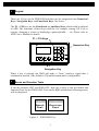
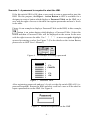
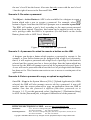
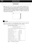
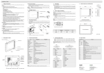
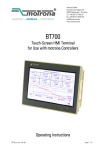
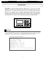
PWS6300S
Operating Guide
HITECH
Introduction
PWS6300S is a Human Machine Interface (HMI) with a 3" STN LCD of a high
resolution (160?80) and is IP65/NEMA4 proof with water and dust-resistant. The
PWS6300S is CE marked and meets your need to be highly transient-resistant
while it is in operation. Also, its compact design makes connections with other
machinery more flexible, thus achieving the optimal performance of your machines.
The latest released ADP Version 6.0 and above is used to design applications of
the PWS6300S; it is reliable, user-friendly and compatible with many models.
HITECH
Electronics Corp.
F7
A
F8
7
F4
D
F5
4
F1
C
E
F6
5
F
6
F3
2
3
F10
Shift
1
F9
9
F2
1
(A..F)
B
8
BS
0
ESC
Self-test
Once the PWS6300S is turned on, it will automatically execute a self-test to check
its hardware. The result of a self-test is displayed on the LCD. See below.
The items to check in a self-test:
BIOS Version V1.0
(C) 2004 HITECH CORP
System RAM.... 128KB
Flash Memory.... 4MB
Battery check..... ?(or x)
Parameter check... ?(or x)
BIOS check........ ?(or x)
Firmware check.... ?(or x)
Application check. ?(or x)
RTC check......... ?(or x)
DIP SW 8~1: 11011111 (or other combinations)
Figure 1. PWS6300S Power-on Self-test
-1-
If any of the above items does not pass a self-test, the following message will be
displayed on the screen for about two seconds and then disappeared.
Error code: 0x18
Wait for a minute
to continue
If power to the HMI or the PC was interrupted while downloading, the item “Firmware check” or “Application check” will not pass a self-test and will be checked
with an “x” mark after power is restored. The situation is normal and users can
simply follow the download procedures to re-download an application or data.
After downloading, all items should pass the next self-test.
2
System Menu
Set the dip switch SW7=ON. After a self-test, the System Menu of the PWS6300S
should be displayed on the screen:
Wait command…
Link
F7
F8
Confg Copy
F9
Run
Figure 2. PWS6300S System Menu
Note that when a command is highlighted on the screen with a black background,
this indicates that the command is currently being executed by the PWS6300S.
Command with gray background (e.g. F7, F8 …) could be executed if the
associated function keys are pressed. The functions of the commands are briefly
explained in the following table:
PWS6300S System Menu
Function
Link
The HMI is connected.
F7 - Confg
Set up the internal time clock and communication
parameters in the HMI. Use ? and ? to move to
desired field and ? and ? to set the value of the field.
F8 - Copy
Copy application data to another PWS6300S.
F9 - Run
Run an application.
-2-
3
Keypad
There are 16 keys in the PWS6300S and they can be categorized into Numerical
Keys, Navigation Keys and Functional Keys. See below.
The F1 ~ F10 keys are the Functional or Auxiliary Keys which could be defined
in ADP. The functions of these keys could be, for example, setting a PLC bit or
register, changing a screen or displaying a password table … etc. Please refer to
ADP User’s Manual for details.
F1 ~ F10 Keys
HITECH
Numerical Key
Electronics Corp.
F7
A
F8
7
F4
F9
8
D
F5
4
F1
C
9
E
F6
5
F
6
F3
F2
1
2
3
F10
Shift
(A..F)
B
BS
0
ESC
Navigation Key
When a key is pressed, the HMI will make a “beep” sound to signal that a
command is pressed. (The default is 200 milli-seconds and is configurable.)
4
Bench and Function Tests
If the dip switches SW3 and SW4=OFF, then one is able to run the Bench and
Function Tests for the PWS6300S. Turn on the HMI and then the following screen
will be displayed:
F9
F6
Bench
Test
Function
Test
Figure 3. PWS6300S Test
-3-
The test items are listed in the following table:
PWS6300S Tests
F9 – Bench Test
F6 – Function Test
5
Items
Keyboard Test: 16 keys.
BIOS: System RAM, Flash memory, Buzzer, LED,
BIOS, Battery Status, RTC, COM port, Flash
ROM.
F1: LED
F5: RS232
F2: Buzzer
F6: RS422
F3: DIP SW
F7: RS485
F4: LCD
F8: KEY
Setting Parameters
There are two options to configure working parameters; a user can set parameters
in the HMI or ADP. To set parameters in the HMI, select F7 – Confg in the
System Menu. Remember to set the dip switch SW5=ON if parameters are set in
the HMI.
A user can also choose to set parameters in ADP. To set parameters in ADP, select
[Application] / [Workstation Setup]. On the [Connection] tab, a user is then able to
set communication parameters. Remember to set the dip switch SW5=OFF if
parameters are set in ADP.
6
Downloading an Application
First make sure that the HMI and the PC are connected. The way to connect the
HMI and the PC is illustrated below:
PWS-COM2
PC COM RS232
9-pin male--------- 9-pin female
RXD
TXD
GND
RTS
CTS
2
3
5
7
8
3 SD
2 RD
5 SG
8 CTS
7 RTS
6 DSR
1 CD
4 DTR
PWS
PC
-4-
-5-
Warning: To avoid an electronic shock, be sure to switch off the power before connecting the
download cable to the HMI.
Set the dip switch SW7=ON. After a self-test, the System Menu will be displayed
on the screen and the PWS6300S is ready to download an application.
Open an application file to be downloaded in ADP and make sure that communication parameters are correctly configured. Also remember to compile a file before
downloading if not yet. Please note that one needs to compile a file before
downloading or anytime a change has been made in a file.
Next select [Application] / [Download Firmware and Application]in ADP if it is a
first time to download an application to the HMI; otherwise, select [Application] /
[Download Application]. The following should appear on the screen while the
PWS6300S is downloading:
Programming AP…
Link
7
Uploading an Application
An application can also be uploaded from the HMI to the PC. Thus, a user can save
an application as a *.V6F file in ADP for future use.
Warning: To avoid an electronic shock, be sure to switch off the power before connecting the
communication cable to the HMI.
Make sure that the HMI and the PC are connected, shown as in Section _6_. Set the
dip switch SW7=ON. After a self-test, the System Menu will be displayed on the
screen and the PWS6300S is ready to upload an application.
Also make sure that communication parameters are correctly configured. Select
[File] / [Upload Application] in ADP and the [Save As] dialogue box will appear
on the screen. Enter the name of a firmware file (*.AF6) to save. Click [Save].
Then the HMI will prompt a user to ask for a password: enter the password set in
ADP from [Application] / [Workstation Setup]. Once a password is entered, the
PWS6300S starts to upload an application to the PC. (For setting a password,
-6-
please refer to Section _9_.) While the PWS6300S is uploading, its screen should
appear as the following:
Uploading FW …
Link
After uploading, select [File] / [Reconstruct Source] in ADP and the [Open] dialogue box will appear on the screen. Open an uploaded application file (*.C64 or
*.AA6) and then an application screen will show up in the PC. Finally, select [File]
/ [Save As] to save an application as a *.V6F file. Thus a source file can serve the
purposes of maintenance and modification.
8
Copying
In the System Menu, select F8 – Copy to copy an application from the PWS6300S
to the other PWS6300S. Set the dip switch SW7=ON and connect two PWS6300S
with a download cable in COM2. After a self-test, the System Menu will be
displayed on the screen.
Select F8 – Copy in the System Menu from the PWS6300S with the application to
be copied. The HMI will prompt a user to ask for a password: enter the password
set in ADP from [Application] / [Workstation Setup]. Once a password is entered,
the PWS6300S starts to copy an application to the other PWS6300S. (For setting a
password, please refer to Section _9_.) The followings should appear on the
screens while the PWS6300S is copying an application to the other:
Copying FW…
Copy
Figure 4. Copying to the other
PWS6300S
9
Programming FW…
Link
Figure 5. Copying from the other
PWS6300S
Setting a Password - 4 Scenarios
-7-
Scenario 1: A password is required to start the HMI.
If the dip switch SW6 is ON, then a user needs to enter a password to start the
HMI. For this purpose, the Object - Action Button in ADP is available for a
designer to create a button which displays a Password Table on the HMI, so a
user with the right of access to the table can register passwords and user’s levels
in the table.
Figure 6 is an example to display a Password Table on the HMI; in this example,
button is an action button which displays a Password Table. Select this
button and then a Password Table will be displayed on the screen for the user
with the right to access the table. Use ? ? ? ? to move and
to highlight
an area for entering a value. See Figure 7. (For the details on the Action Button,
please refer to ADP User’s Manual.)
Figure 6. An example of setting a password
#
Password Lv1
1
2
3
4
5
6
7
8
00000000
00000000
00000000
00000000
00000000
00000000
00000000
00000000
1
1 F1:
1 CANCEL
1
1
1 F2:
1 OK
1
Figure 7. Password Table
After registering passwords and user’s levels, set the dip switch SW6=ON (i.e.
password required). Restart the HMI and after a self-test a user will be asked to
input a password to run the HMI. See Figure 8.
Figure 8. Password required to run the HMI
-8-
The HMI will determine a user’s level from a password entered by a user. For
instance, if the level of a password entered by a user is 1, then the HMI will set
the user’s level=1; if the level of a password entered by a user is 2, then the
HMI will set the user’s level=2. The user’s level 1 has the highest privilege and
-9-
the user’s level 9 has the lowest. Also note that only a user with the user’s level
1 has the right of access to the Password Table.
Scenario 2: Re-enter a password.
The Object - Action Button in ADP is also available for a designer to create a
button which asks a user to re-enter a password. For example, select
button in Figure 9 and then the HMI will prompt a user to re-enter a password.
The HMI will update a user’s level according to the most recent password
which has been entered. Therefore, this button can be applied to raise or drop
one’s privilege while the HMI is in operation. (For the details on the Action
Button, please refer to ADP User’s Manual.)
Figure 9. The HMI asks for a password.
Scenario 3: A password is asked to execute a button on the HMI.
A designer can design a button which requires a password to execute it. For
example, a Goto Screen button can be designed with a high level of security;
that is, it will require a password with a high level of privilege.As the button is
selected and the current user has a lower privilege than the button which has
been set for, the HMI will prompt a user to ask for a password, also see Figure 9.
A user will need a password with at least the level of privilege which the button
has been set for. This function can restrict a user to access to certain parts of an
application.
Scenario 4: Enter a password to copy or upload an application.
Once F8 – Copy in the System Menu or [File] / [Upload Application] in ADPis
selected, the HMI will also prompt a user to ask for a password. A user will
need to enter the correct password to copy an application from one HMI to
another. Note that this password is different from those passwords set in
Scenario 1~3. To set this password, select [Application] / [Workstation Setup]
in ADP. On the [Password] tab, a designer is then able to set the password.
HITECH ELECTRONICS CORP.
Head Office:
Marketing Division:
Web Site: http://www.hitechsite.com
th
4 Fl., No 501-15 Chung-Cheng Rd., Shin-Tien, Taipei Shien, Taiwan, R.O.C.
Tel: 886-2-22183600
Fax: 886-2-22183060
4th Fl., No 501-15 Chung-Cheng Rd., Shin-Tien, Taipei Shien, Taiwan, R.O.C.
Tel: 886-2-22180660
Fax: 886-2-22189547
Copyright © 2004 Hitech Electronics Corp. All rights reserved. Specification subject to change without notice