1
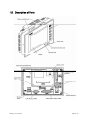
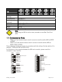
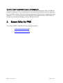
control – motion – interface
motrona GmbH
Zwischen den Wegen 32
78239 Rielasingen - Germany
Tel. +49 (0)7731-9332-0
Fax +49 (0)7731-9332-30
[email protected]
www.motrona.com
BT700
Touch-Screen HMI Terminal
for Use with motrona Controllers
Operating Instructions
BT700_e.doc / Feb-09
Page 1 / 19
Safety Instructions
• This manual is an essential part of the unit and contains important hints about
function, correct handling and commissioning. Non-observance can result in
damage to the unit or the machine or even in injury to persons using the
equipment!
• The unit must only be installed, connected and activated by a qualified electrician
• It is a must to observe all general and also all country-specific and applicationspecific safety standards
• When this unit is used with applications where failure or maloperation could cause
damage to a machine or hazard to the operating staff, it is indispensable to meet
effective precautions in order to avoid such consequences
• Regarding installation, wiring, environmental conditions, screening of cables and
earthing, you must follow the general standards of industrial automation industry
• - Errors and omissions excepted –
This product is manufactured by
and in this context intended for use as a
proved and recommended accessory part
with motrona motion control products
BT700_e.doc / Feb-09
Page 2 / 19
Table of Contents
1. PWS6600 Installation ..................................................................................... 4
1.1.
1.2.
1.3.
1.4.
1.5.
1.6.
1.7.
Introduction ...........................................................................................................4
Safety Precautions ................................................................................................4
General ..................................................................................................................4
Package Contents..................................................................................................6
Mounting Procedure..............................................................................................6
Grounding ..............................................................................................................6
BT700_e.doc / Feb-09
Page 3 / 19
1.4. Package Contents
1.5. Mounting Procedure
1. Cut out the control front panel to match the dimensions (mm) specified under the
External and Cut-out dimensions chapter.
2. Mount the HMI into the cut-out. Insert the fixtures to the holes on the unit and fasten
the screws into the front panel. Do not tighten the screws with too much or uneven
force, or it may cause deformation of the HMI.
3. The HMI must be installed within an angle of 0° to 135° as shown above.
1.6. Grounding
Make sure that the HMI works properly. To prevent it from radiating radio frequency
noise, the HMI must be connected to earth ground.
o Without grounding, the HMI may be severely affected by excess noise. Make sure that the
grounding is done properly from the power connector at the rear side of the HMI. When
power is connected, make sure that the wire is grounded.
o Use a cable of at least 2 mm2 (AWG 14) to ground the HMI. Ground resistance must be less
than 100 Ohms (class3). Note that the ground cable must not be connected to the same
ground point as the power circuit.
BT700_e.doc / Feb-09
Page 6 / 19
1.7. Power Supply and Wiring
The HMI must use a power supply with 24 V DC and the power consumption is 20W.
Warning:
To avoid an electric shock, be sure to switch off the power before connecting
the communication/download cable to the HMI.
Steps to wire
1. Unplug the power connector and unscrew the screws.
2. Strip about 1 cm of insulation. Insert the wire all the way into the power connector and
then turn the screws tight.
3. Plug in the connector to the power outlet of the HMI.
Note:
Power connector is already plugged in the power outlet of the HMI when the
package is first opened.
1.8. External and Cut-out Dimensions
(7.303” +/- 0.02)
(2.323”)
(5.346” +/-0.02)
(1.827”)
(7.283”)
(0.165”)
BT700_e.doc / Feb-09
(5.315”)
(5.709”)
(7.677”)
Page 7 / 19
1.9. Description of Parts
BT700_e.doc / Feb-09
Page 8 / 19
1.10. Product Specifications
Item
BT700_e.doc / Feb-09
PWS
6600C-N
AP
1600C-N
PWS
6600C-P
AP
1600C-P
Page 9 / 19
Item
Electrostatic
discharge
RF Susceptibility
High Frequency
Transients
External dimensions
Cut-out dimensions
Weight
Cooling
PWS
PWS
6600C-N 6600C-P
AP
AP
1600C-N 1600C-P
IEC61000-4-2
PWS
6600C-S
AP
1600C-S
PWS
6600S-P
AP
1600S-N
PWS
6600S-P
AP
1600S-P
PWS
6600S-S
AP
1600S-S
IEC61000-4-3
IEC61000-4-4
195.0 x 145.0 x 59.1 mm
185.8 x 135.8 mm
0.81 kg
Natural cooling
Note:
When using the HMI for the first time, remember to reset Real Time Clock
(RTC).
1.11. Communication Ports
– COM 1 is a 9-pin female connector used to connect a controller and the HMI via RS232
or RS485
– COM 2 is a 25-pin female connector used to connect a controller and the HMI via
RS232, RS422 or RS485
Please make sure that the connection is in accordance with the setting of the dip switches. (For
example, , RS485 with SW9 and SW10=ON).
For illustration on the connection between the HMI and a controller, please consult the
information on the controller.
COM1
1
9
2
8
3
7
4
6
5
Function
RS485+
Optional +5V@ 100mA ouput
RS232 RXD
RS232 CTS
RS232 TXD
RS232 RTS
N/A
RS485Signal ground
COM2
1
14
2
15
3
16
4
17
5
18
6
19
COM3
1
20
RS422+ (RS485 TX+)
21
8
9
2
8
3
7
4
6
5
BT700_e.doc / Feb-09
7
Function
RS422 CTS+
RS422 RTSRS422 CTS+
RS422 RTS+
RS422 RX+
RS422-(RS485 TX-)
Signal ground
9
22
10
23
11
24
12
25
13
Function
N/A
RS422 TX- (RS485+)
RS232 TXD
RS422 TX- (RS485-)
RS232 RXD
RS422 RX+
RS232 RTS
RS422 RXRS232 CTS
N/A
N/A
N/A
Signal ground
N/A
Optional +5V @ 100mA output
N/A
N/A
N/A
N/A
RS422 RTS+
N/A
RS422 RTSRS422 CTS+B
N/A
RS422 RTS-
Page 10 / 19
1.12. Dip Switches
Dip Switches
SW 1
SW 2
SW 3
SW 4
ON
ON
ON
OFF
OFF
ON
OFF
OFF
SW 5
ON
OFF
SW 6
ON
BT700_e.doc / Feb-09
Function
Reserved
Reserved
Operation Mode
Runs user application
Runs burn-in test program
Updates BIOS
Runs bench test program
Communication Parameters
The HMI uses parameters defined on the Configuration Screen for
controller communications
The HMI uses parameters defined in ADP for controller communications
Password
The HMI asks the operator to enter
Page 11 / 19
2.
PWS6600 Operation
2.1. Self Test
Once the HMI is turned on, it will automatically execute a self-test to check its hardware.
The result of a self-test is displayed on the LCD. See below for items to check
in a self-test:
Human Machine Interface
ROM BIOS Version 1.6
(C) 2005 Hitech Beijer Electronics
Display Type = Mono STN LCD
System RAM Size
Video RAM Size
Battery Backed RAM Size
Application Memory Size
Working RAM Test
Battery Status
BIOS ROM Checksum
Firmware Checksum
Application Checksum
RTC Function Test
Parameter Checksum
Communication Port 1 Test
Communication Port 2 Test
DIP Switches Setting(8..1)=
256K Bytes
256K Bytes
512K Bytes
4M Bytes
Passed
Passed
Passed
Passed
Passed
Passed
Passed
Passed
Passed
11011111
If any of tests does not pass the self-test, it will be noted with “Failed” next to the test item.
Additionally, the message “Error! Press screen to continue” will be displayed at the bottom of
the screen.
If the power to the HMI or the PC was interrupted while downloading, Firmware checksum or
Application checksum will not pass the self-test, indicated by “Failed” in the self-test results
after power is restored. If this happens, the user can simply follow the download procedure to
re-download the application or data. After downloading again, all items should pass the selftest.
BT700_e.doc / Feb-09
Page 12 / 19
2.2. System Menu
Set the dip switch SW7=ON. After the self-test, the system menu of the HMI is displayed on
the screen:
BT700_e.doc / Feb-09
Page 13 / 19
2.4. Bench and Function Tests
Set the dip switches SW3 and SW4=OFF to be able to run the bench and function tests for the
HMI. Turn on the HMI and the following screen will be displayed.
F1
Bench Test
F2
Function Test
The bench test performs an overall hardware test and the function test lets the user select
which item to be tested.
Note:
The bench test will clear the application data of the HMI.
2.5. Setting Communication Parameters
There are two ways to configure working parameters; to set parameters in the HMI or in ADP.
To set parameters in the HMI, select F2 - Confg in the system menu.
Note:
Remember to set the dip switch SW5=ON if parameters are set in the HMI
To set parameters in ADP, select Application / Workstation Setup. Then select the Connection
tab to set communication parameters.
Note:
Remember to set the dip switch SW5=OFF if parameters are set in ADP
2.6. Downloading an Application
Connect the RS232 port on the PC to the COM1 port on the HMI using a WPCP8- 42 cable. The
connection can also be made according to the illustration below.
BT700_e.doc / Feb-09
PWS-COM1
PC COM RS232
PWS-COM2
PC COM RS232
9-pin male
9-pin female
25-pin male
9-pin female
Page 14 / 19
Warning:
To avoid an electronic shock, be sure to switch off the power before
connecting the download cable to the HMI.
Set the dip switch SW7 = ON. After the self-test, the system menu will be displayed
on the screen and the HMI is ready to download the application.
Start ADP and open the application file to be downloaded. Make sure that the communication
parameters are correctly configured. Also remember to compile the file before downloading it.
The file has to be compiled every time a change has been made in the file before downloading
it.
Then select Application/Download Firmware and then Application in ADP if it is a first time to
download the application to the HMI; otherwise, select Application/Download Application. The
following appears on the screen while the HMI is downloading:
Programming application..
Link port: COM1
F2
2.7. Uploading an Application
An application can also be uploaded from the HMI to the PC. Thus, a user can save an
application as a *.V6F file in ADP for future use.
Warning:
To avoid an electric shock, be sure to switch off the power before connecting
the communication cable to the HMI.
Make sure that the HMI and the PC are connected according to section “Downloading an
Application”. Set the dip switch SW7 = ON. After the self-test, the system menu will be
displayed on the screen and the HMI is ready to upload the application.
Also make sure that communication parameters are correctly configured. Select File/Upload
Application in ADP and the Save As dialog box will appear on the screen. Enter the name of a
firmware file (*.AF6) to save. Click Save. Then the HMI will prompt for a password: enter the
password set in ADP from Application/Workstation Setup. Once the correct password is
entered, the HMI starts to upload the application to the PC. For information about setting a
password, please see section “Setting a Password“.
BT700_e.doc / Feb-09
Page 15 / 19
While the HMI is uploading, the following is displayed:
Uploading firmware...
Link port: COM1
F2
After uploading, select File/Reconstruct Source in ADP to display the Open dialog.
Open the uploaded application file (*.C64 or *.AA6). The application screen will be
displayed on the PC monitor. Finally, select File/Save As to save the application as a
*.V6F file. Thus a source file can serve the purposes of maintenance and modification.
Note:
When using the HMI for the first time, reset the real time clock (RTC).
2.8. Uploading / Downloading a Recipe
Set the dip switch SW7 = ON. After the self-test, the system menu will be displayed on the
screen and the HMI is ready to upload/download a recipe.
Uploading a Recipe
Select File/Upload Recipes in ADP and the Save As dialog box will appear on the screen. Enter
the name of a recipe file (*.RCP) to save. Click Save. While the HMI is uploading the recipe,
Uploading recipes is displayed on the screen.
Downloading a Recipe
Open an application file with the recipe to be downloaded in ADP. Select File/Download
Recipes to display the Open dialog. Enter the name of the recipe file (*.RCP) and click Open.
While the HMI is downloading the recipe, Downloading recipes is displayed on the screen:
Uploading recipes...
Link port: COM1
F2
Downloading recipes...
Link port: COM1
F2
After the download is finished, select F5 - Run to run the application.
Remember to define the length and the number of recipes in the application. Also remember to
upload the format of recipes from the HMI before starting to edit a new set of recipe data in
the PC.
For further information about creating/editing recipes, please see the corresponding chapter in
the ADP User’s Manual.
BT700_e.doc / Feb-09
Page 16 / 19
2.9. Copying an Application
To copy an application from one HMI to another, select F3 - Copy from the system menu. Set
the dip switch SW7 = ON and connect the two HMIs with a download cable. After the self-test,
the system menu will be displayed on the screen.
Select F3 - Copy in the system menu from the HMI with
will prompt for a password: enter
Application/Workstation
Setup. OnceT0c-correct password
t to copy 0c-application
on the screens during 0c-copying:
Copying firmware...
Link port: COM1
F2
Programming Firmware...
Link port: COM1
F2
Note:
If it is the first time to copy, please remember to run the application.
2.10. Setting a Password
Scenario 1: Requiring a password to start the HMI
If the dip switch SW6 = ON, the user needs to enter a password to start the HMI.
For this purpose, the designer can use the object Action Button in ADP to create a button which
displays the password table on the HMI display. A user with the right to access the table can
register passwords and user levels in the table. In the illustration below, the TBL-button is an
action button used to display the password table.
When the button is selected the password table is displayed on the screen for a user with the
right to access the table. Touch the password to highlight an area for entering a value.
In the illustration above, the TBL-button is an action button used to display the password table.
When the button is selected the password table is displayed on the screen for a user with the
right to access the table. Touch the password to highlight an area for entering a value.
BT700_e.doc / Feb-09
Page 17 / 19
How to configure an Action Button is described in the ADP User’s Manual.
After registering passwords and user levels, set the dip switch SW6 = ON (i.e. password
required). Restart the HMI and after the self-test the user will be prompted to enter a password
in order to run the HMI. The HMI will determine the user level from the entered password. For
instance, if the level of the password entered by the user is 2, then t
BT700_e.doc / Feb-09
Page 18 / 19
Scenario 4: Requiring a password to copy or upload application
When selecting F3 - Copy in the system menu or File/Upload Application in ADP, the HMI will
prompt for a password. The user will need to enter the correct password to copy an application
from one HMI to another. Note that setting this password is different from the passwords set in
Scenarios 1-3. To set this password, select Application/Workstation Setup in ADP. Under the
Password tab, the project designer is able to set the password.
3.
Screen Editor for PWS
The software ADP6 is available from the following websites.
• http://www.hitechsite.com
• http://www.hitechsite.com.tw
BT700_e.doc / Feb-09
Page 19 / 19