1
Scene PD 6.0
User's Guide
Scene PD 6.0
User's Guide
Scene PD 6.0
Copyright © 1999-2014 A-T Solutions, Inc. All rights reserved
All rights reserved. No parts of this work may be reproduced in any form or by any means - graphic, electronic, or
mechanical, including photocopying, recording, taping, or information storage and retrieval systems - without the
written permission of the publisher.
Products that are referred to in this document may be either trademarks and/or registered trademarks of the
respective owners. The publisher and the author make no claim to these trademarks.
While every precaution has been taken in the preparation of this document, the publisher and the author assume no
responsibility for errors or omissions, or for damages resulting from the use of information contained in this
document or from the use of programs and source code that may accompany it. In no event shall the publisher and
the author be liable for any loss of profit or any other commercial damage caused or alleged to have been caused
directly or indirectly by this document.
Generated: August 2014 in Boise, Idaho, USA.
Contents
5
Table of Contents
Foreword
0
Part I Welcome to Scene PD
10
Part II Introduction
14
1 Why Scene
...................................................................................................................................
PD
14
2 About...................................................................................................................................
help
15
3 Getting
...................................................................................................................................
the most from help
16
4 Acknowledgements
................................................................................................................................... 16
Part III Scene PD Basics
20
1 Activating
...................................................................................................................................
Scene PD
20
2 User interface
................................................................................................................................... 21
Getting to know
..........................................................................................................................................................
the m ain w indow
22
3 Starting
...................................................................................................................................
a casebook
23
Starting a new..........................................................................................................................................................
casebook w ith form s
23
Opening a saved
..........................................................................................................................................................
casebook
25
Searching for..........................................................................................................................................................
a casebook
27
Starting a new..........................................................................................................................................................
casebook w ith a diagram
28
Part IV Working with forms
32
1 Data validation
................................................................................................................................... 32
2 Managing
...................................................................................................................................
forms
32
Adding form s.......................................................................................................................................................... 33
Reordering form
..........................................................................................................................................................
s
34
Deleting form..........................................................................................................................................................
s
35
3 Navigating
...................................................................................................................................
within a casebook
36
Navigating w ithin
..........................................................................................................................................................
a form
37
Navigating to another
..........................................................................................................................................................
form
39
Part V Working with diagrams
42
1 Getting
...................................................................................................................................
to know the diagram editing window
42
2 Performing
...................................................................................................................................
basic tasks
44
Manipulating shapes,
..........................................................................................................................................................
sym bols and text
44
Using handles.......................................................................................................................................................... 52
Zoom ing
.......................................................................................................................................................... 52
Undoing/redoing
.......................................................................................................................................................... 54
Starting over .......................................................................................................................................................... 55
Working w ith..........................................................................................................................................................
the clipboard
55
3 Working
...................................................................................................................................
with structures, streets, symbols and field
56
measurements
Base layer
.......................................................................................................................................................... 57
Streets ......................................................................................................................................................... 58
Lanes & Shoulders
......................................................................................................................................................... 68
Copyright © 1999-2014 A-T Solutions, Inc. All rights reserved
5
6
Scene PD 6.0
Dividers ......................................................................................................................................................... 74
Stripes ......................................................................................................................................................... 77
Structures......................................................................................................................................................... 80
Labels
......................................................................................................................................................... 87
Sym bols layer.......................................................................................................................................................... 89
Working w.........................................................................................................................................................
ith symbols
89
Symbol types
......................................................................................................................................................... 99
Symbol examples
......................................................................................................................................................... 101
Measurem ents
..........................................................................................................................................................
layer
110
Triangulation
......................................................................................................................................................... 110
Station line
......................................................................................................................................................... 114
Area tools......................................................................................................................................................... 122
4 Advanced
...................................................................................................................................
diagram tasks
123
Configuring ..........................................................................................................................................................
user options
123
Using draw ing
..........................................................................................................................................................
tools
128
Working w ith
..........................................................................................................................................................
tem plates
132
Creating a.........................................................................................................................................................
draw ing template
132
Adding a .........................................................................................................................................................
template group
133
Handling special
..........................................................................................................................................................
situations
134
Show ing .........................................................................................................................................................
original vehicle position
135
Show ing .........................................................................................................................................................
vehicle damage
135
Adding an.........................................................................................................................................................
overpass
137
Draw ing unusual
.........................................................................................................................................................
street layouts
137
5 Lessons
................................................................................................................................... 139
144
Part VI Working with attachments
1 Adding
...................................................................................................................................
attachments to a casebook
144
2 Linking
...................................................................................................................................
attachments to a diagram
146
3 Working
...................................................................................................................................
with non-image attachments
147
4 Entering
...................................................................................................................................
attachment information
148
5 Working
...................................................................................................................................
with image attachments
148
Annotating an
..........................................................................................................................................................
im age
149
Rotating an im
..........................................................................................................................................................
age
151
Adjusting im..........................................................................................................................................................
age appearance
152
Cropping an..........................................................................................................................................................
im age
153
Saving an im..........................................................................................................................................................
age
154
Part VII Output: print, PDF, PowerPoint, export
158
1 Printing
...................................................................................................................................
a casebook
158
2 Printing
...................................................................................................................................
a diagram to scale
160
3 Creating
...................................................................................................................................
a PDF
162
4 Creating
...................................................................................................................................
a PowerPoint presentation
163
5 Exporting
...................................................................................................................................
a drawing
164
Part VIII Quick reference
166
1 Keyboard
...................................................................................................................................
shortcuts
166
2 Computer
...................................................................................................................................
conventions
168
3 Menus
...................................................................................................................................
and toolbars
168
Copyright © 1999-2014 A-T Solutions, Inc. All rights reserved
Contents
7
Menu bar .......................................................................................................................................................... 169
Toolbars
.......................................................................................................................................................... 171
Layers tabset
.......................................................................................................................................................... 176
Properties bar
.......................................................................................................................................................... 178
Index
179
Copyright © 1999-2014 A-T Solutions, Inc. All rights reserved
7
Part
I
10
1
Scene PD 6.0
Welcome to Scene PD
Scene PD (SPD ) is a powerful software program designed to
manage forms, digital evidence, and 2D diagrams. Scene PD software allows
operators to quickly and efficiently document and report upon criminal acts,
RECON Operations, Interdiction Tactics, Site Surveys, IED Disruption/RSP, and
Post Blast Forensics.
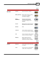
Providing "tip of the spear" capability, Scene PD includes the following:
Form data
Scene PD's Case Manager window provides the ability to construct
a casebook containing the forms relevant to the incident. Custom
form development helps ensure familiarity to the field operator
while tailored drop-down menus increase speed and accuracy.
Rich Text
Scene PD's text editor provides a spell-checked text window
where descriptive information regarding the case can be recorded.
GPS Stamping
GPS Stamping allows the field operator to assign an accurate LAT/
LONG to the individual incident report to support future spatial
analysis.
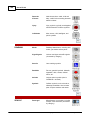
Diagrams
Using A-T Solutions' proven diagramming technology, Scene PD's
diagram editor enables users to quickly and accurately draw any
incident scene. Scene PD provides a large selection of pre-drawn
streets, structures, vehicles, bodies, and various other symbols.
In addition, Scene PD includes many application-specific
"intelligent" shapes to make the drawing process easier and more
effective.
Digital Evidence
Scene PD's Attachment facility provides tools to attach digital
photographs, audio and video recordings and other forms of digital
Copyright © 1999-2014 A-T Solutions, Inc. All rights reserved
Welcome to Scene PD
evidence. Scene PD's photo manipulation tools make it easy to
annotate, rotate, and adjust the brightness and contrast of
attached photographs without altering the original.
Analysis Repository Integration
Scene PD supports nearly all delimited exports for easy
integration into any existing analysis repositories, including
XML, PDF, and PowerPoint. And with an extremely small data
and diagram file size, real-time reporting has never been
easier!
Copyright © 1999-2014 A-T Solutions, Inc. All rights reserved
11
Part
II
14
2
Scene PD 6.0
Introduction
The topics in this section show you how Scene PD, coupled with this help file, can
make reporting easier and more efficient.
Topics include:
Why Scene PD
About help
Getting the most from help
Acknowledgements
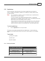
2.1
Why Scene PD
Scene PD was developed with the end user in mind. It is designed for in-field use including use on tablet PCs, with or without internet connectivity. Best of all, it's
EASY to use! With very little training you can document and storyboard any pre or
post action incident.
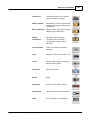
Documentation may include:
DATA COLLECTION
Customizable form libraries
Drop down menus
Rich text editing
Diagrams/photos embedded in entry forms
DIAGRAMMING
Drag and drop engine.
Scaled/vector engine
Complete symbol libraries, including the most comprehensive library of current
military vehicles
Proven reliability - used by over 300,000 in the law enforcement community
DIGITAL EVIDENCE ATTACHMENT
Attach any electronic evidence such as photos, video, office documents
Copyright © 1999-2014 A-T Solutions, Inc. All rights reserved
Introduction
Annotate or enhance photographs without altering the original
Register evidence to diagrams
GPS/MGRS coding of incident file
DATA SHARING
Extremely small data and diagram file size
Export capability to PDF, PowerPoint, image files
And we do not intend to stop there. Utilizing User Groups, we rely on experts in
the field to validate relevancy and accuracy of applications.
2.2
About help
This guide will walk you through three fundamental electronic information types
that make up Scene PD: 1) form entry; 2) diagrams; and 3) evidence management
(photos, video, audio, pdf, MS Office).
You will find information organized according to the following main topics:
Basics
Scene PD basics covers software activation, the user interface, and starting
a casebook.
Forms
Working with forms introduces the case manager, as well as provides an
overview of form navigation and validation.
Diagrams
Working with diagrams deals with tasks performed on the diagram editor including topics for each each of the three layers.
Attachments
Working with attachments includes information for getting the most out of the
Scene PD attachment feature.
Output
The Output topic encompasses the various output options, including print,
export, and PDF and PowerPoint creation.
Quick reference
Lastly, this help file contains a quick reference. The quick reference includes
topics such as keyboard shortcuts, conventions, and menu/toolbar overview topics that can make your work in Scene PD all the more efficient.
Copyright © 1999-2014 A-T Solutions, Inc. All rights reserved
15
16
2.3
Scene PD 6.0
Getting the most from help
The step-by-step instruction in this help file will assist you in completing tasks
quickly and easily. In most cases, there is more than one way to perform a task.
We describe the preferred method for performing a task and include alternative
methods when available, so you can choose what works best for you.
Not sure where to begin? If you are new to Scene PD, we encourage you to start
at the beginning and work your way down.
You may also want to consider the following:
Getting started
If you have not yet registered your software, Activating Scene PD will explain how to
go about doing so.
Review the Quick reference topics for keyboard shortcuts and conventions, as well as
an overview of the menus and toolbars available in Scene PD.
Learning more
See Advanced diagram tasks to learn how to configure user options, use drawing
tools, work with templates, and handle special drawing situations.
Read over Working with attachments to learn how to get the most out of the
attachment feature.
Check out the Output: print, PDF, PowerPoint, export topic to discover the various
ways you can disseminate casebook information as quickly and easily as possible.
And keep an eye out for the following ...
Not
e
Take note of important details provided here - they alert you to what you can
expect while working in Scene PD.
Tip!These helpful hints are located throughout this help manual - highlighting even
more ways to make your job easier and more efficient.
2.4
Acknowledgements
Adobe® and Adobe® Reader® are registered trademarks of Adobe Systems
Incorporated in the United States and/or other countries.
Microsoft ®, PowerPoint ®, Windows®, and Windows Vista™ , Windows XP™ , and
Copyright © 1999-2014 A-T Solutions, Inc. All rights reserved
Introduction
Windows 7™ operating systems are registered trademarks of Microsoft Corporation
in the United States and other countries.
Copyright © 1999-2014 A-T Solutions, Inc. All rights reserved
17
Part
III
20
3
Scene PD 6.0
Scene PD Basics
This section provides you a broad overview of the basics! Here you'll find
everything you need to get started from Activating Scene PD to starting a
casebook.
Topics include:
Activating Scene PD
User interface
Starting a casebook
Note
3.1
This manual may contain descriptions of some elements or features that are not
present in your installation of Scene PD. If you would like to add these
features, contact A-T Solutions.
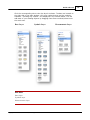
Activating Scene PD
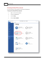
Once you have installed the Scene PD software, you will need to activate your
license(s). You have three options for activation: Internet, Phone, or Email.
Ope n Sc e ne PD, a nd c lic k t he Ac t iv a t e link from t he "Ev a lua t e Ea sy St re e t Dra w " sc re e n.
Choose one of t he t hre e opt ions t o a c t iv a t e y our Sc e ne PD lic e nse :
Option #1: Activate online
1.
Click Activate online, then click the Next button.
2.
When prompted, use the License ID and Password, as provided with your
software. If desired, you can also specify an Installation Name.
Note:
Passwords are case sensitive.
Option #2: Activate Manually
Note:
You will be asked to provide the following for manual activation: License ID
(as noted in Option#1), and Password. You will need an Internet connection to
perform manual activation.
1.
Click Activate Manually, then click the Next button.
2.
Enter your License ID and Password into the text fields provided, then click the
Generate Request button. An activation request code will be generated and
displayed.
3.
Copy the activation request code to your clipboard using the Copy button, then
Copyright © 1999-2014 A-T Solutions, Inc. All rights reserved
Scene PD Basics
21
click the Open Activation Web Page button and paste the code. Click the
Submit button.
4.
An activation code will be generated and displayed. Copy it to your clipboard,
then paste it into the Activation Code text field. Click the Next button.
5.
Click the Finish button on the Congratulations screen.
Option #3: Activate by telephone
Note:
3.2
You will be asked to provide the following for phone activation: License ID (as
noted in Option#1), System ID 1 and System ID 2 (as accessed below)
1.
Click Activate by Telephone – you will be provided two (2) System ID numbers.*
2.
Follow the steps displayed in the "To activate Scene PD" section of the
Registration & Activation screen.
3.
When all fields have been filled out, click the Next button.
4.
Click the Finish button on the Congratulations screen.
User interface
Being familiar with the main window can make your work in Scene PD even more
productive. This section will introduce you to the various parts of the main
window.
See Also:
Getting to know the diagram editing window
Quick reference
Copyright © 1999-2014 A-T Solutions, Inc. All rights reserved
22
3.2.1
Scene PD 6.0
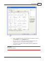
Getting to know the main window
Before using Scene PD, you should become familiar with the main window...
Menu bar and toolbars
Scene PD has a standard menu bar and several toolbar tabs at the top of the
main window. You can access most commands in two ways:
From the menu bar
-OR-
Copyright © 1999-2014 A-T Solutions, Inc. All rights reserved
Scene PD Basics
From the toolbar
When you are working on a drawing in Scene PD's diagram editor, you can
access context-related menus by right-clicking on a drawing symbol.
Not
e
See Also:
Getting to know the diagram editing window
Menu bar
Toolbars
3.3
Starting a casebook
The Case Wizard window automatically opens when you start Scene PD. The Case
Wizard provides four activity tabs: New Case, Cases on File, Search, and New
Drawing.
This section provides an overview of each activity.
Topics include:
Starting a new casebook with forms
Opening a saved casebook
Searching for a casebook
Starting a new casebook with a diagram
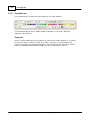
3.3.1
Starting a new casebook with forms
Your Scene PD application contains at least one formset with at least one
summary and one diagram form. In most instances you will begin a new casebook
using one or more of these forms.
Copyright © 1999-2014 A-T Solutions, Inc. All rights reserved
23
24
Scene PD 6.0
Starting a casebook with forms
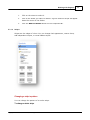
To start a new casebook that includes forms, you'll begin with the New Case tab.
Not
e
Form libraries made available to you depend on your specific Scene PD
installation. If you have access to multiple formsets, you will select a formset
before selecting individual forms.
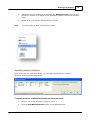
To start a casebook using forms
1.
Select the New Case tab.
2.
Select a formset from the top window. A list of the forms that make up that
formset will appear in the "Contents of <whatever the name of the formset is>"
window below. That list is for your information only; you can't change the
composition or order of forms in a formset from here.
Note
If you have a single formset available, you will bypass step two and go directly
to choosing forms for your casebook (Step 4).
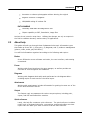
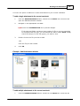
3.
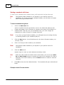
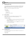
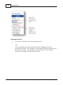
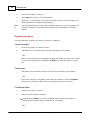
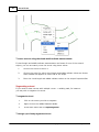
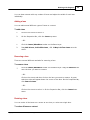
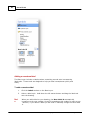
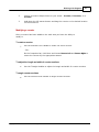
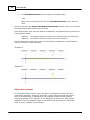
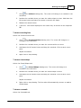
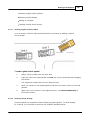
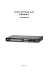
Click the Next button. You will be directed to the Active Formset window; se e
e xa m ple , be low .
4.
Click on a form you wish to add to your casebook.
Note
5.
Form libraries made available to you depend on your specific Scene PD
installation.
Click the Add button.
Repeat steps 4-5 until you have added all necessary forms.
Not
e
6.
When the Case Forms list contains two or more forms, you can use the Move
Up and Move Down buttons to reorder the forms in the casebook. If a form is
selected in the Case Forms list, click the Delete button to remove it from the
casebook.
Click OK to close the Case Wizard window. The casebook will open with selected
forms.
Example: Active Formset window
Copyright © 1999-2014 A-T Solutions, Inc. All rights reserved
Scene PD Basics
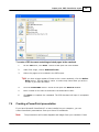
3.3.2
25
Opening a saved casebook
If you need to review, edit, or complete a saved casebook, you will want to
access the Cases on File tab and select the appropriate file.
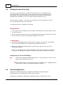
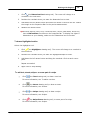
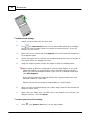
To open a saved casebook
1.
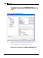
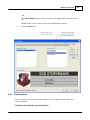
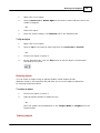
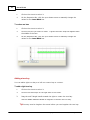
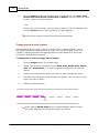
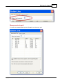
Click the Cases on File tab on the Case Wizard window. Se e e xa m ple , be low .
2.
Select the appropriate folder from the navigation tree.
3.
Double-click on the file you wish to open.
-ORSelect the file you wish to open.
4.
Click OK to open the selected casebook.
Copyright © 1999-2014 A-T Solutions, Inc. All rights reserved
26
Scene PD 6.0
Tip!If you frequently open files in the same folder, navigate to that folder using
the navigation tree and then click the Remember this Folder button. The
selected folder will become the default starting location for the Cases on File
window.
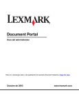
Example: Case Wizard Cases on File page
Not
e
When you open the Cases on File page, the window to the left displays all the
folders on your computer's hard drive and other storage devices.
Use the + buttons to open folders and access additional files.
When you select a folder from Cases on File folder tree, all Scene PD files will
display in the window to the right. When you select a file, any notes
associated with the casebook will be displayed in the Case Notes window.
Copyright © 1999-2014 A-T Solutions, Inc. All rights reserved
Scene PD Basics
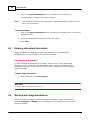
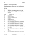
3.3.3
27
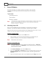
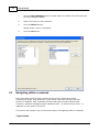
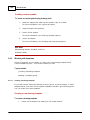
Searching for a casebook
With the Case Wizard's search feature, you have the ability to search your saved
casebooks for a specific word or phrase.
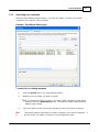
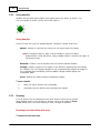
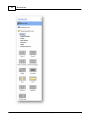
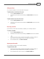
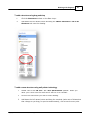
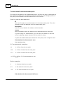
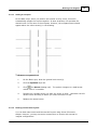
Example: Case Wizard Search page
To search for an existing casebook
1.
Click the Search tab on the Case Wizard window.
2.
Browse to the file folder you wish to search.
Tip!If you frequently search for files in the same folder, navigate to that folder
and then click the Remember button. The selected folder will become the
default search folder.
3.
Not
e
Type your search string (the word or phrase for which you want to search).
The search feature will search for words or phrases in the actual casebook - it
will not search for words or phrases in the casebook file name.
Copyright © 1999-2014 A-T Solutions, Inc. All rights reserved
28
Scene PD 6.0
4.
Click Go to find all casebooks in selected folder that contain the search string.
Casebooks will be listed in the Results window.
5.
Double-click on the casebook file you wish to open.
-ORClick on the casebook file you wish to open.
6.
3.3.4
Click OK.
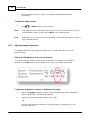
Starting a new casebook with a diagram
Scene PD provides you the option to open a single diagram page.
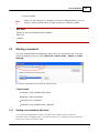
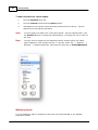
Starting a casebook with a diagram
If you only need to complete a new diagram, you'll select the New Drawing tab.
When creating a new drawing, you will usually begin with a drawing template. A
template provides a basic layout for the diagram. The top area of the New Drawing
window provides several buttons; each button provides access to a specific
template group.
Note:
Template names/options may vary depending on your specific Scene PD
installation.
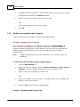
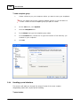
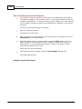
To start a new casebook with a single template diagram
1.
Click the New Drawing tab.
2.
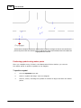
Browse through the template groups (Streets, Structures, Circuits, Injury, or
Samples) to find a template similar to the scene you wish to draw.
3.
Double-click on the template you wish to use.
-OR-
4.
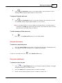
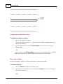
Select the template you wish to use. A thumbnail image of the template will
display in the preview window.
5.
Click the OK button to open the drawing page.
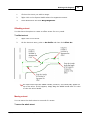
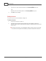
Example: Case Wizard New Drawing Page
Copyright © 1999-2014 A-T Solutions, Inc. All rights reserved
Scene PD Basics
29
Tip
s!
Once a template is selected, you can change the template’s rotation.
Under Preview, click the Rotation arrows.
You can create your own drawing templates and add them to the
template selections. See Creating a drawing template.
If you prefer to start with a blank drawing, simply click OK without
selecting a template.
See Also:
Working with diagrams
Copyright © 1999-2014 A-T Solutions, Inc. All rights reserved
Part
IV
32
4
Scene PD 6.0
Working with forms
Scene PD casebooks are composed of forms. Form libraries are installation specific,
but all forms may include text entry boxes, drop-down menus, check boxes, date
selection and GPS acquisition buttons, and diagram drawing and narrative text
areas.
This section focuses on how to manage your work in Scene PD.
Topics include:
Data validation
Managing forms
Navigating within a casebook
4.1
Data validation
Scene PD gives you the option of validating your data before dissemination.
Validation helps to ensure you did not miss any required fields.
To validate a casebook
1.
Click the Validate button, located near the bottom of the Scene PD window.
Scene PD will check each form field in sequence, stopping at the first item
that fails the validation test.
2.
4.2
To continue the validation process, click the Next button in the lower left
corner of the Scene PD window.
Managing forms
The Case Manager manages the forms you have available for each casebook. This
section shows you how ...
Topics include:
Copyright © 1999-2014 A-T Solutions, Inc. All rights reserved
Working with forms
33
Adding forms
Reordering forms
Deleting forms
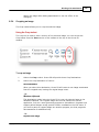
4.2.1
Adding forms
You have the option to add additional forms to the current casebook.
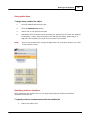
To add a form to the current casebook
1.
Click the Case Manager button, located under the toolbar. Scene PD will open
the Case Manager window.
2.
Select the form you wish to add.
Not
e
3.
Form libraries made available to you depend on your specific Scene PD
installation.
Click the Add button. The form will be displayed in the Case Contents window.
Repeat steps 2 and 3 until you have added all forms you wish to add.
4.
Click the OK button to return to the open casebook.
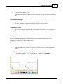
Example: Case Manager window
Copyright © 1999-2014 A-T Solutions, Inc. All rights reserved
34
4.2.2
Scene PD 6.0
Reordering forms
You have the ability to change the order of most forms in your casebook.
Reordering forms in casebook
Forms will be displayed in the order they were selected. You can change the order
from the Case Manager.
Not
e
Forms that have text fields linked to subsequent forms will always be listed
before the others. Therefore, such forms will have limited reorder-capability.
To change the order of the forms in the current casebook
1.
Click the Case Manager button located under the toolbar. Scene PD will open
the Case Manager window.
2.
Select the form you wish to move.
3.
Click the Move Up button until the form is the appropriate order within the list.
Copyright © 1999-2014 A-T Solutions, Inc. All rights reserved
Working with forms
35
-ORClick Move Down button until the form is in the appropriate order within the
list.
Repeat steps 2 and 3 until all forms are appropriately ordered.
4.
4.2.3
Click the OK button.
Deleting forms
If you no longer need a form that was added, you can simply remove it from the
current casebook.
To delete a form from the current casebook
Copyright © 1999-2014 A-T Solutions, Inc. All rights reserved
36
Scene PD 6.0
1.
Click the Case Manager button located under the toolbar. Scene PD will open
the Case Manager window.
2.
Select the form you wish to delete.
3.
Click the Delete button.
Repeat steps 2 and 3 if necessary.
4.
4.3
Click the OK button.
Navigating within a casebook
Each form within Scene PD may contain several types of data entry boxes including text boxes, drop down lists, check boxes, and date and GPS selection
buttons. In addition, each casebook will more than likely contain multiple forms.
Therefore, seamless navigation within individual forms - as well as form to form - is
important to your work in Scene PD.
This section will introduce you to the various ways of navigating within a casebook.
Topics include:
Copyright © 1999-2014 A-T Solutions, Inc. All rights reserved
Working with forms
37
Navigating within a form
Navigating to another form
4.3.1
Navigating within a form
Understanding the various ways of navigating a casebook allows you to decide for
yourself the quickest and most efficient way to get from point A to point B.
Navigating within a form
To navigate to an entry box
Click the mouse in the entry box you wish to access.
-ORPress the TAB key on your keyboard. The cursor will move to the next entry box
on the form.
To scroll a form vertically
Use the scrollbar at the right edge of the form window.
-ORIf your mouse or other pointing device includes a scroll wheel, you can scroll the
form by rolling the wheel.
Navigating to a word processing or diagramming editor
If the current form contains a diagram area or an extended text area, such as narrative
or incident description, Scene PD will open a separate editing window.
To navigate to the diagram editor
Click on the diagram area (it will usually read Click to edit or something similar).
Scene PD will replace the form editing window with the diagram editor.
-OROn the form navigator, click on the Diagram that drops down below the
appropriate form. This will navigate directly to the diagram editor.
After you complete work on the diagram, you can return to the form by selecting its name
on the form navigator.
Copyright © 1999-2014 A-T Solutions, Inc. All rights reserved
38
Scene PD 6.0
To navigate to the word processing editor
Click the rich text entry box (it will usually read Click to edit or something
similar). Scene PD will replace the form editing window with the word processing
editor.
-OROn the form navigator, click on the Summary that drops down below the
appropriate form. This will navigate directly to the word processing editor.
After you complete entry in this editor, you can return to the form by selecting its name
on the form navigator.
Form entry keyboard shortcuts
Most form entry items provide keyboard shortcuts for activation.
Examples:
To select a check box, press the TAB key on your keyboard until the active
context box (a blue dashed rectangle) moves to the checkbox; press the
spacebar to select the checkbox.
When you tab to a list item, Scene PD will automatically expand the list. To
select an item in the list click it with the mouse.
-OR-
Copyright © 1999-2014 A-T Solutions, Inc. All rights reserved
Working with forms
39
Press the down arrow until the desired item is selected.
-ORBegin typing the name of the desired item. Scene PD will auto-complete the name
of the item using the letters you have entered so far. Continue typing until the
correct item is selected and then press the TAB key to move to the next form
item.
To open the diagramming editor using the keyboard, tab to the diagram box on
the form and press the spacebar.
To open the word processing editor using the keyboard, tab to the text display
box on the form and press the spacebar.
See Also:
Keyboard shortcuts
4.3.2
Navigating to another form
Scene PD allows you the ability to move from one form to another with just a click
of the mouse.
Navigating to another form
To move from form to form, use the Forms navigator pane on the left hand side of
the Scene PD window.
Copyright © 1999-2014 A-T Solutions, Inc. All rights reserved
40
Scene PD 6.0
To navigate to a form
Click on the form name in the Forms navigator pane.
-ORThe form navigator pane also includes the names of diagrams and word
processing text boxes in the casebook. These pages drop down from the form of
which they are a part. By selecting one of these items, you can navigate
directly to the diagram or word processing editor.
Copyright © 1999-2014 A-T Solutions, Inc. All rights reserved
Part
V
42
5
Scene PD 6.0
Working with diagrams
Scale diagramming is core to all Scene PD reports. With Scene PD, you are supplied
with intelligent libraries and tools to rapidly create detailed and accurate scenes.
This section contains topics that will help ensure you get the most of the diagram
editing window.
Topics include:
Getting to know the diagram editing window
Performing basic tasks
Working with structures, streets, symbols and field measurements
Advanced diagram tasks
5.1
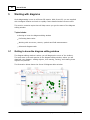
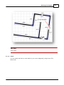
Getting to know the diagram editing window
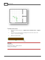
The diagram editing window is where you will diagram the scene of the incident.
The work area is the main portion of the diagram editing window, where you will
draw/edit your diagram - adding objects, then moving, resizing, and rotating those
objects into position.
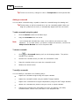
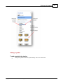
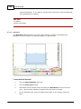
The illustration below shows the Scene PD diagram editor window.
Copyright © 1999-2014 A-T Solutions, Inc. All rights reserved
Working with diagrams
43
Accessing the diagram editor window
You may access the diagram editor window from any diagram form or directly from the
form navigator.
To access the diagram work area
Click "Click to edit" (or similar phrase) in the diagram field.
-OROn the form navigator, click on the Diagram drop-down, under the appropriate
form. This will take you directly to the diagram editor window.
Diagram Editor elements
Grid toggle button
To view a measurement grid in the work area, click the grid toggle ("Show
Grid") button. Click the button again to deactivate the grid.
Zoom tools
The zoom tools are used to zoom in or out on the drawing.
Work area
The work area is the central portion of the screen; it contains your
drawing. This is the area where you will add shapes to the drawing. Shapes
that have been added can then be moved, resized, and rotated into
position.
Layer selectors
Layer selectors are located to the right of the work area. These selectors are
used to move between the different layers of the drawing. Incident scenes are
made up of three layers:
The Base layer, where you draw structures and streets.
The Symbols layer, where you draw furnishings, clues, vehicles and other
objects important to the scene.
The Measurements layer, which provides tools to accurately position
marker points using the baseline/offset or Triangulation measurement
method.
Properties bar
Copyright © 1999-2014 A-T Solutions, Inc. All rights reserved
44
Scene PD 6.0
The Properties Bar is located at the bottom of the main window. You can
modify an object by changing the settings displayed on the Properties Bar.
The Properties Bar acts as a smart toolbar - changing as you select different
objects in the drawing. For example, select a street shape and the properties
of that street are displayed, including the street’s name, number of lanes, lane
width, and more. Click on a vehicle, and the properties will change to that of
the selected vehicle.
Layers toolsets
Scene PD provides custom toolsets for each layer. The toolsets are located
at the right of the main window. Each button provides access to a different
toolset containing the available tools and symbols. You will add most of your
diagram objects by dragging them from a toolset onto the work area.
Drawing toolbar
If you can't find an object you need in one of the toolsets, you can always
create your own with the drawing tools. For ease of access, Scene PD
displays the drawing toolbar directly above the work area.
See Also:
Menus and toolbars
5.2
Performing basic tasks
Before getting started with a drawing, it's a good idea to understand a few of the
basic tasks associated with its creation. This section covers those basics.
Topics include:
Manipulating shapes, symbols and text
Using handles
Zooming
Undoing/redoing
Starting over
Working with the clipboard
5.2.1
Manipulating shapes, symbols and text
Here's what you'll find in this topic...
Copyright © 1999-2014 A-T Solutions, Inc. All rights reserved
Working with diagrams
Adding objects
Modifying objects
Deleting objects
Copying objects
Repositioning objects
Resizing objects
Ordering objects
Selecting multiple objects
Aligning multiple objects
Grouping and ungrouping objects
45
Your diagram will be made up of a wide variety of shapes, symbols, and text.
Understanding how to manipulate the various pieces is vital to the success of your
drawing.
Adding objects
To add an object
Hold down the left mouse button and drag the object from the layer toolset onto
the work area.
Tip!You can also draw an object using the drawing tools. For more information,
see using drawing tools.
To add text to an object
1.
Click on the object to select it.
2.
Begin typing. The text will automatically appear on or near the object.
- OR Type the text in the Text box located on the Properties Bar.
To add a text box
1.
2.
Click
(the Text Box drawing tool) on the drawing toolbar. Your cursor will
turn to a crosshair next to a boxed A in the work area.
Position the crosshair where you wish the text box to start. Hold down the left
mouse button and drag to create the text box. When you release the mouse
button, the Edit Text window will appear.
3.
Type your text.
4.
Click OK.
Copyright © 1999-2014 A-T Solutions, Inc. All rights reserved
46
Scene PD 6.0
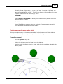
To add a unit label to a vehicle symbol
1.
Click the Symbols layer tab.
2.
Click the Vehicle toolset and the Labels subset.
3.
Hold down the left mouse button and drag a label onto the vehicle. A green
selection line will indicate placement.
Note
You can modify the label once it has been placed: On the Properties Bar, click
the Position button to change the label position; or change the size or color of
the font.
Note
You may need to toggle on the Advanced Vehicle toolset before the Labels
option appears in your toolset selector. To do this, select File --> Options -->
Drawing --> Symbol Collections, and check the box next to VehicleAdvanced.
Modifying objects
You can modify an object’s properties from either the Properties Bar or the Symbol
Properties window.
Copyright © 1999-2014 A-T Solutions, Inc. All rights reserved
Working with diagrams
47
To modify an object
Click on the object to select it and change its properties on the Properties Bar.
- OR 1.
Right-click on the object and click Properties on the shortcut menu. The
Shape/Symbol Properties window will open.
2.
Make changes as needed.
3.
Click OK to save changes.
Tip!For some objects, more settings are available on the Symbol Properties
window than on the Properties Bar.
Deleting objects
To delete an object
1.
Click on the object to select it.
2.
Click
(the Cut button) on the main toolbar.
- OR Press the DELETE key on your keyboard.
Copying objects
To copy an object
Hold down the CTRL key on your keyboard and drag the object you want to
copy.
The original remains intact as you drag the copy. This is the fastest way to copy
an object.
- OR 1.
Click on the object to select it.
2.
Click
3.
(the Copy button) on the main toolbar.
Click
(the Paste button) on the main toolbar to paste the object onto the
work area.
- OR -
Copyright © 1999-2014 A-T Solutions, Inc. All rights reserved
48
Scene PD 6.0
1.
Click on the object to select it.
2.
Press Ctrl + C to copy it to the clipboard.
3.
Press Ctrl + V to create a new copy of the object, which you can drag to the
desired location (see Repositioning objects).
Not
e
The newly pasted copy of the object will be exactly on top of the original; you
will have to drag the copy before you will be able to distinguish it from the
original.
Repositioning objects
You can reposition an object by moving, rotating, or flipping it.
To move an object
1.
Click on the object you want to move.
2.
Hold down the left mouse button and drag the object into position.
- OR Use the arrow keys on your keyboard to move the shape up, down, left or right.
To accelerate movement, hold down the SHIFT key while pressing the arrow
key.
To move text
Hold down the left mouse button on the text box and drag it into position.
- OR If the text is linked to a symbol (a Unit label for instance), click the Position
button on the Properties Bar until the text appears where you want it.
To rotate an object
1.
Click on the object to select it.
2.
Drag the Circle Handle to rotate it.
Tip!Hold down the CTRL key on your keyboard while rotating the symbol to
constrain the rotation angle to multiples of 15 degrees.
- OR -
Copyright © 1999-2014 A-T Solutions, Inc. All rights reserved
Working with diagrams
49
1.
Right-click on the object.
2.
Point to Rotate Left or Rotate Right on the shortcut menu and then select the
number of degrees.
- OR -
1.
Select the object.
2.
Enter the rotation angle in the Rotation box on the Properties Bar.
To flip an object
1.
Right-click on the object.
2.
Point to Flip on the shortcut menu and then click Horizontal or Vertical.
- OR -
1.
Click on the object to select it.
2.
On the Properties Bar, click the Flip button to flip the object in the direction
indicated by the arrow.
Resizing objects
You can resize an object using its Square Handles. Some shapes provide
dimension items on the Properties Bar and allow you to set the object’s dimensions
by entering the desired values.
To resize an object
1.
Click on the object to select it.
2.
Drag the Square Handles to adjust its size.
- OR Enter the shape’s actual dimensions in the Length, Width, or Height box on the
Properties Bar.
Ordering objects
Copyright © 1999-2014 A-T Solutions, Inc. All rights reserved
50
Scene PD 6.0
Scene PD displays objects in the order they are added to the drawing. When two
objects overlap, the object added first will appear to be under the object added
later. You can, however, arrange an object so that it is in front of or behind
another object, despite placement order.
Note
The above does not apply to streets.
To arrange an object
1.
Right-click on the object.
2.
On the shortcut menu, point to Arrange and then click Bring to Front or Send
to Back.
Note
You can only change the order of objects that are on the same layer. Objects
on the Base layer will always appear under objects on the Symbols layer.
Selecting multiple objects
To select multiple objects at once, you can drag a selection box around the
objects. This is useful for deleting, copying, moving, aligning, or grouping multiple
objects.
Note
You can only select objects that are on the same layer.
To select multiple objects
1.
Click in an empty area of the drawing.
2.
Hold down the left mouse button and drag the pointer across the work area.
A selection box will appear as you drag.
3.
When the box contains the shapes you want to select, release the mouse
button.
All shapes within the selection box will be selected.
Tip!You can also select multiple objects by holding down the SHIFT key on your
keyboard as you click each object.
To select all the objects on a layer
On the Edit menu, click Select All.
Copyright © 1999-2014 A-T Solutions, Inc. All rights reserved
Working with diagrams
51
Aligning multiple objects
You can align objects at their left, right, top, or bottom edges.
Note
You can only align objects that are on the same layer.
To align multiple objects
1.
Select the objects you want to align. See "Selecting multiple objects."
2.
Right-click on an empty area. Do NOT right-click on the objects or you will lose
your multiple selection.
3.
On the shortcut menu, point to Align and then click Left, Right, Top, or
Bottom.
Grouping and ungrouping objects
You can group objects together so they move and act as one, or ungroup an
object to modify its components.
Note
You can only group objects that are on the same layer.
To group objects
1.
Select the objects you want to group together. See "Selecting multiple objects."
2.
Right-click on an empty area. Do NOT right-click on the objects or you will lose
your multiple selection.
3.
On the shortcut menu, click Group.
To ungroup an object
1.
Right-click on the object.
2.
On the shortcut menu, click Ungroup.
See Also:
Using Handles
Copyright © 1999-2014 A-T Solutions, Inc. All rights reserved
52
5.2.2
Scene PD 6.0
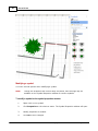
Using handles
Handles are the small green shapes that appear when you select an object. You
can use handles to resize, rotate, and curve objects.
Using handles
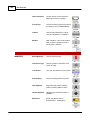
Scene PD uses four types of handles:Square, Diamond, Triangle, and Circle.
Square: Resizes or relocates the section of the object near the handle.
Tip!On rectangular objects, drag a corner handle to resize the object
proportionally in both directions. Drag a middle handle to stretch the object in
one direction only.
Diamond: Creates a curve between the two nearest Square Handles.
Triangle: Adjusts a portion of an object in the direction indicated by the triangle.
For example, the end Triangle Handles on the crosswalk shape adjust the length of
the crosswalk lines individually, and the middle Triangle Handles adjust the
crosswalk’s width.
Circle: Rotates the object without changing its shape.
To use a handle
5.2.3
1.
Move the mouse pointer over the handle.
2.
Hold down the left mouse button and drag the handle.
Zooming
You can zoom in on your drawing to see more detail or zoom out to provide
more drawing space in the work area. Another useful zoom option is Zoom
To Fit, which puts your entire drawing in view, as large as possible.
Zooming in and out of the work area
To zoom in to the work area
Copyright © 1999-2014 A-T Solutions, Inc. All rights reserved
Working with diagrams
53
Click
(the Zoom In button) on the main toolbar; this will zoom in to the
drawing, making images appear larger on your screen.
To zoom out from the work area
Click
(the Zoom Out button) on the main toolbar; this will zoom out from
the drawing, making images appear smaller on your screen.
Tip! You can also zoom in or out by rolling your mouse wheel. (You may need to
hold down the CTRL key while rolling the wheel. If this does not work, see the
documentation provided with your mouse.)
To fit the drawing to fill the work area
Click
(the Zoom to Fit button) on the main toolbar.
Using the lasso zoom
To zoom in on a particular area
Click the Lasso Zoom button under the Zoom tool and drag a rectangle around
the object(s) you wish to zoom in on. Repeat as necessary.
To Return to normal view click
(the Zoom to Fit button).
Using lasso print/export
To zoom to an area for print
1.
Click
(the Lasso Export button) on the main toolbar and drag a rectangle
around the object(s) you wish to print.
2.
Click the Print button, displayed above the lasso rectangle.
3.
Select correct printing options (printer, number of copies, etc.)
Copyright © 1999-2014 A-T Solutions, Inc. All rights reserved
54
Scene PD 6.0
4.
Click Print.
To export an area of the drawing as an image file
1.
Click
(the Lasso Print/Export button) on the main toolbar and drag a
rectangle around the object(s) you wish to export.
2.
Click the Export button, displayed above the lasso rectangle.
3.
Select the file location in which you wish to save your file.
4.
Name the file.
5.
Select the desired file format.
6.
Click Save.
See Also:
Printing a casebook
Exporting a drawing
5.2.4
Undoing/redoing
If you take an action and then change your mind, you can undo it. If you undo an
action and then change your mind, you can redo it.
To undo an action
Click
(the Undo button) on the main toolbar.
- OR Press CTRL + Z.
Tip!You may undo any number of actions by continuing to click
(the Undo
button) on the main toolbar.
To redo an action
On the Edit menu, click
(the Redo button).
Copyright © 1999-2014 A-T Solutions, Inc. All rights reserved
Working with diagrams
5.2.5
55
Starting over
You can erase the current scene and start over with a new scene.
To start over
1.
On the Scene menu, click
Scene window will appear.
(the Erase & Start Over button). The New
2.
Select a new drawing template (Optional).
3.
Click OK.
Tip!If you change your mind and wish to return to the original drawing, click
(the Undo button) on the main toolbar.
Not
e
5.2.6
The Erase & Start Over command replaces the contents of the current drawing.
If your casebook contains multiple drawings, the other drawings in the casebook
will remain unchanged.
Working with the clipboard
The clipboard makes it easy to duplicate objects, move objects from one layer to
another, or copy objects or even an entire drawing from Scene PD to another
program.
To duplicate an object using the clipboard
1.
Click on the object to select it.
2.
On the toolbar for the Shape or Diagram tab, click Copy.
-ORClick
3.
(the Copy tool) on the main toolbar.
On the toolbar for the Shape or Diagram tab, click Paste.
-ORClick
(the Paste tool) on the main toolbar.
To create additional copies, repeat the Edit, Paste commands.
Tip!The quickest way to duplicate a shape is to select the shape, hold down the
CTRL key on the keyboard, and then drag the shape with the mouse. As you
begin to drag the shape, Scene PD will make a duplicate of the shape. The
Copyright © 1999-2014 A-T Solutions, Inc. All rights reserved
56
Scene PD 6.0
mouse will drag the duplicate, leaving the original shape unchanged.
To move an object from one layer to another
1.
Click on the object to select it.
2.
On the toolbar for the Shape or Diagram tab, click Cut.
-ORClick
(the Cut tool) on the main toolbar.
3.
Navigate to the destination layer.
4.
On the toolbar for the Shape or Diagram tab, click Paste.
-ORClick
(the Paste tool) on the main toolbar.
To copy an image of the drawing to another program
1.
On the toolbar for the Diagram tab, click the Copy Drawing button.
2.
Switch to the other program using the taskbar.
- OR Start the program using the Start menu.
3.
5.3
In the destination program, click Paste on the Edit menu.
Working with structures, streets, symbols and field
measurements
In most cases, Scene PD divides your diagram drawing into three layers. The
layers tabset, located along the right side of the work area, allows you move
between the layers of your drawing.
Note
The layers noted above apply to most diagram drawings. There are, however,
exceptions to the rule. If you are using a drawing template that is focused in
scope, such as a Circuit or Injury, layers will vary.
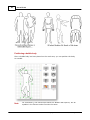
For example, if you are creating a Personal Injury drawing using one of the
templates supplied with Scene PD, the drawing layers will be Person and
Copyright © 1999-2014 A-T Solutions, Inc. All rights reserved
Working with diagrams
57
Labels. The person outline will be on the Person layer; and you will use the
Labels layer to add symbols for bruises, broken bones, burns or other injury
marks.
This section helps you make the most of each diagram layer.
Topics include:
Base layer
Symbols layer
Measurements layer
5.3.1
Base layer
You will begin your new scene drawing on the Base Layer. The Base Layer is the
foundation of your drawing - it is where you draw and edit streets and structures.
To view the base layer
Click the Base Layer tab in the Symbols panel to the right side of the work
area.
Buttons for Street, Structure, and other tools are located to the right of the
main window. Each button provides access to a different toolset.
Tools and tool subsets are located in the window below the toolset buttons. You
will add most of your drawing’s objects by dragging them from a toolset onto the
work area.
Not
e
It is a good idea to complete as much of the Base Layer as possible before
adding other symbols.
This topic covers the major tasks associated with the base layer.
Topics include:
Streets
Lanes & Shoulders
Dividers
Stripes
Copyright © 1999-2014 A-T Solutions, Inc. All rights reserved
58
Scene PD 6.0
Structures
Labels
5.3.1.1
Streets
Here's what you'll find in this topic...
Adding a street
Segmenting a street
Curving a street
Offsetting a street
Moving a street
Naming a street
Modifying a curb return
Adding a crosswalk
Adding parking stalls
In Scene PD, streets are composed of lanes, dividers, stripes, and shoulders. When
you click on a street, the entire street operates as an intelligent shape; the
changes you make with the mouse affect the entire street.
If the scene includes streets, laying out your street design should be your first step.
Copyright © 1999-2014 A-T Solutions, Inc. All rights reserved
Working with diagrams
Not
e
59
In most cases, streets should only be placed on the Base Layer. An overpass is
one exception to this rule. When you draw an overpass on the Symbols layer,
the overpass appears over any streets on the Base Layer.
Modifying street components
You can modify a component of the street, such as a lane, stripe, or shoulder.
To modify a street component
1.
Click on the street to select it.
2.
Click the street component you want to change. It will become highlighted and
its settings will appear on the Properties Bar below the work area.
3.
Change the settings on the Properties Bar.
Note
If you try to move or resize a part of the street by dragging it, the entire street
shape will move.
Adding a street
You can add a new street using a street symbol or draw the street using the
drawing tools.
Note
Before adding a street, be sure you are on the Base Layer. To view the Base
Layer, click the Base Layer toolset link in the Layer Selector.
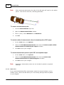
To add a street using a street tool
1.
Click the Streets toolset.
2.
Hold down the left mouse button and drag the Vertical, Horizontal, or Offset
tool onto the work area.
Copyright © 1999-2014 A-T Solutions, Inc. All rights reserved
60
Scene PD 6.0
Copyright © 1999-2014 A-T Solutions, Inc. All rights reserved
Working with diagrams
61
To draw a street
1.
Click
(the Streets drawing tool) on the drawing toolset. The pointer
changes to a small street outline next to a crosshair.
2.
Position the crosshair where you want the street to start.
3.
Drag the crosshair where you want the street to end.
4.
Release the mouse button.
Curving a street
You can add one curve or multiple curves to a street.
To add one curve
Click on the street to select it. Drag the middle Diamond Handle to add a curve.
To add multiple curves
1.
Right-click on the street.
2.
On the shortcut menu, point to Set Profile and then click Double Arc or Triple
Arc, depending on how many curves you need.
3.
Drag the Diamond Handles to increase or decrease the curves.
Copyright © 1999-2014 A-T Solutions, Inc. All rights reserved
62
Scene PD 6.0
To curve a street using chord and middle ordinate measurements
If chord length and middle ordinate measurements are known for one of the street’s
stripes, you can accurately curve the street using these values.
1.
Click on the street to select it.
2.
Click on the stripe for which chord length and middle ordinate values are known.
Green handles will appear on either side of the stripe.
3.
Enter the chord length and middle ordinate values on the stripe’s Properties Bar.
Segmenting a street
If you need to draw a street with multiple curves - a winding road, for instance you may wish to segment the street.
To segment a street
1.
Click on the street you wish to segment.
2.
Right-click on the middle Diamond Handle.
3.
Scroll down menu and click Split Segment.
To merge a previously segmented street
Copyright © 1999-2014 A-T Solutions, Inc. All rights reserved
Working with diagrams
1.
Click on the street you wish to merge.
2.
Right-click on the Square Handle where the segments connect.
3.
Scroll down menu and click Merge Segments.
63
Offsetting a street
You also have the option to create an offset street for curvy roads.
To offset a street
1.
Right-click on the street.
2.
On the shortcut menu, point to Set Profile and then click Offset Arc.
Tip!An offset street has two middle handles, however, one handle may appear on
top of the other. If this happens, simply drag the middle handle that is in view
to view the other handle.
Moving a street
You can move the whole street or one end of a street.
To move the whole street
Copyright © 1999-2014 A-T Solutions, Inc. All rights reserved
64
Scene PD 6.0
1.
Click on the street to select it.
2.
Hold down the left mouse button and drag the street to the desired location.
If the street touches another street, Scene PD automatically merges the two
streets together once you release the left mouse button.
Tip!When moving a street shape to join another, be sure to position the street so
both street borders touch the other street. If only one border touches the
other street, the stripes may not have the desired appearance.
To move one end of a street
1.
Click on the street to select it.
2.
Use the Square Handle on the end of the street to drag it to the desired
location.
The street realigns itself between the two Square Handles.
Naming a street
To name a street
Copyright © 1999-2014 A-T Solutions, Inc. All rights reserved
Working with diagrams
1.
Click on the street to select it.
2.
Type the name of the street.
65
The name you enter will appear on the work area, as well as on the Properties
Bar.
To reposition the name
Hold down the left mouse button on the text box containing the name you want
to move, and drag it anywhere inside or near the street shape.
To modify the name
Click on the name to select it and then change the settings on the Properties
Bar.
Modifying a curb return
Scene PD automatically places a standard curb return between two streets that
intersect. You can modify this standard curb.
To modify a curb return
1.
Click the curb return to select it. Two Square Handles appear.
2.
Drag the handles up or down the street until the curb return has the desired
shape.
Tip!For precise placement, adjust the setback value using the increment/
decrement buttons on the Properties Bar, or watch the Setbacks
measurements on the Properties Bar as you drag the handles.
Copyright © 1999-2014 A-T Solutions, Inc. All rights reserved
66
Scene PD 6.0
Tip!To hide a curb return, change its color to Transparent on the Properties Bar.
Adding a crosswalk
You can add a crosswalk using a symbol or draw the crosswalk using the drawing tool.
Tip!The best way to add a crosswalk is to use the crosswalk symbol. When you
drag the symbol onto a street, it automatically aligns itself with the street.
To add a crosswalk using the symbol
1.
Click the Streets toolset on the Base Layer.
2.
Drag the Crosswalk onto the street.
Note
The crosswalk will automatically "snap" to the sides of the street for easy
alignment. If, for some reason, you wish to change this behavior, uncheck the
Snap to Street Borders box on the Properties Bar.
To draw a crosswalk
1.
Click
(the Crosswalk drawing tool) on the drawing toolbar. The pointer
changes to a crosshair.
2.
Position the crosshair where you want the crosswalk to start.
3.
Drag the crosshair where you want the crosswalk to end.
4.
Release the mouse button.
To modify a crosswalk
You can modify a crosswalk in the following ways:
Adjust the crosswalk’s length using the Square Handles.
Adjust the crosswalk’s width using the middle Triangle Handles.
Adjust each crosswalk line’s length independently using the end Triangle Handles.
Rotate the crosswalk into position using the Circle or Square Handles.
Change the crosswalk style and modify line color, line pattern, line width,
crosswalk width, interior color, and more on the Properties Bar.
Copyright © 1999-2014 A-T Solutions, Inc. All rights reserved
Working with diagrams
67
Adding parking stalls
You can add parking stalls using a symbol or draw the parking stalls using the drawing
tool.
To add parking stalls using a symbol
1.
Click the Streets toolset on the Base Layer.
2.
Drag the Parking Stalls onto the work area.
To draw parking stalls
1.
Click
(the Parking Stalls drawing tool) on the drawing toolbar. The pointer
changes to a crosshair.
2.
Position the crosshair where you want the parking stalls to start.
3.
Drag the crosshair where you want the parking stalls to end.
4.
Release the mouse button.
To modify parking stalls
You can modify parking stalls in the following ways:
Change the number of vehicle stalls and rotate the parking stalls into position
using the Square Handles.
Change the angle of the parking stalls using the Circle Handle (the angle appears
Copyright © 1999-2014 A-T Solutions, Inc. All rights reserved
68
Scene PD 6.0
on the status bar).
Curve the parking stalls using the Diamond Handle.
Modify color, line width, stall width, length, style, and more, on the Properties
Bar.
See Also:
Lanes & Shoulders
Dividers
Stripes
Adding an overpass
Drawing unusual street layouts
5.3.1.2
Lanes & Shoulders
Here's what you'll find in this topic...
Adding a lane
Removing a lane
Resizing a lane
Adding a turn bay
Adding lane markings
Adding shoulders
Removing a shoulder
Adjusting shoulder width
Lanes
Copyright © 1999-2014 A-T Solutions, Inc. All rights reserved
Working with diagrams
69
You can draw streets with any number of lanes and adjust the width of each lane
individually.
Adding a lane
You can add several different types of lanes to a street.
To add a lane
1.
Click on the street to select it.
2.
On the Properties Bar, click the Lanes up arrow.
- OR -
1.
Click the Lanes/Shoulders toolset on the Base Layer.
2.
Drag Add A Lane, Add a Bike Lane, -OR- 2 Way Left Turn Lane onto the
street.
Removing a lane
There are several different methods for removing a lane.
To remove a lane
Click the Lanes/Shoulders toolset on the Base Layer. Drag the Remove tool
onto the lane you want to remove.
- OR Click on the street and then click on the lane you want to remove. A green
selection stripe will appear down the center of the lane. On the Properties Bar,
click Remove Lane.
- OR Click on the street to select it. On the Properties Bar, click the Lanes down
arrow.
Resizing a lane
You can resize all the lanes on a street at one time, or resize one single lane.
To resize all lanes on a street
Copyright © 1999-2014 A-T Solutions, Inc. All rights reserved
70
Scene PD 6.0
1.
Click on the street to select it.
2.
On the Properties Bar, click the up or down arrows or manually change the
values for the Lane Width box.
To resize one lane
1.
Click on the street to select it.
2.
Click on the lane you want to resize. A green selection stripe will appear down
the middle of the lane.
3.
On the Properties Bar, click the up or down arrows or manually change the
values for the Lane Width box.
Adding a turn bay
You can add a right turn bay or a left turn center bay to a street.
To add a right turn bay
1.
Click on the street to select it.
2.
Click on the solid stripe on the right side of the street.
3.
Drag the end Triangle Handle toward the right to create the turn bay.
Use the middle Diamond Handle to lengthen or shorten the turn bay.
Tip!You may need to lengthen the street before you can lengthen the turn bay.
Copyright © 1999-2014 A-T Solutions, Inc. All rights reserved
Working with diagrams
71
EXAMPLE: Right turn bay
To add a left turn center bay
1.
Click on the street to select it.
2.
Click on the rightmost stripe in the center lane.
3.
Use the end Triangle Handle to drag the stripe over, usually so it overlaps the
stripe to the left.
4.
Use the middle Diamond Handle to lengthen or shorten the turn bay.
Adding lane markings
You may add lane and divider markings, such as directional arrows, to your drawing.
Copyright © 1999-2014 A-T Solutions, Inc. All rights reserved
72
Scene PD 6.0
To add lane markings
1.
Click the Lanes/Shoulders toolset on the Base Layer.
2.
Hold down the left mouse button and drag a marking symbol onto the lane or
divider. Use the symbol's handles to resize and rotate the marking as needed.
Shoulders
You can draw streets with one or two shoulders. Shoulders can represent street
shoulders or sidewalks.
Copyright © 1999-2014 A-T Solutions, Inc. All rights reserved
Working with diagrams
73
Adding shoulders
You can place shoulders on one or both sides of the street.
To add shoulders to both sides of the street
1.
Click the Lanes/Shoulders toolset.
2.
Hold down the left mouse button and drag the Add Shoulders tool onto the
street.
To add a shoulder to one side of the street
1.
Click the Lanes/Shoulders toolset.
2.
Hold down the left mouse button and drag the Add Shoulder tool onto one side
of the street.
Removing a shoulder
If you decide you don't want the shoulder you added, you can always remove it.
To remove a shoulder
1.
Click the Lanes/Shoulders toolset.
2.
Hold down the left mouse button and drag the Remove tool onto the shoulder.
- OR -
1.
Click on the street to select it and click the shoulder you want to remove. A
green selection stripe will appear down the middle of the shoulder.
2.
On the Properties Bar, click Remove Shoulder.
Adjusting shoulder width
You can adjust the width of each shoulder individually.
To adjust shoulder width
1.
Click on the street to select it and click the shoulder you want to adjust. A
green selection stripe will appear down the middle of the shoulder.
2.
On the Properties Bar, alter the value in the Shoulder Width box.
Copyright © 1999-2014 A-T Solutions, Inc. All rights reserved
74
5.3.1.3
Scene PD 6.0
Dividers
A divider is simply a lane bordered by special stripes.
Adding a divider to a street
You have a couple options to choose from when adding a divider.
To add a divider using the dividers toolset
1.
Click the Lanes/Shoulders toolset on the Base Layer.
2.
Hold down the left mouse button and drag one of the divider tools over the
street. A selection stripe will appear down the street, indicating position.
3.
Release the mouse button. A divider will appear on the street.
Copyright © 1999-2014 A-T Solutions, Inc. All rights reserved
Working with diagrams
To add a divider using the properties bar
1.
Click on the street to select it.
2.
On the Properties Bar, click the Divider button.
3.
Choose one of the divider options on the popup menu.
EXAMPLE: Painted divider
Copyright © 1999-2014 A-T Solutions, Inc. All rights reserved
75
76
Scene PD 6.0
Changing the width of the divider
To change the width of a divider
1.
Click on the street to select it.
2.
Click in the divider to select it. A green selection stripe will appear down the
middle of the divider.
3.
On the Properties Bar, click the Divider Width arrows until you reach the
desired width.
-OREnter a value in the Divider Width entry box on the Properties Bar. To specify
feet and inches enter a space between the feet and the inch values.
Removing a divider
Scene PD provides a couple of different methods for removing a divider.
To remove a divider
1.
Click the Dividers toolset on the Base Layer.
2.
Hold down the left mouse button and drag the Remove tool onto the divider
you want to remove.
-OR-
Copyright © 1999-2014 A-T Solutions, Inc. All rights reserved
Working with diagrams
5.3.1.4
77
1.
Click on the street to select it.
2.
Click in the divider you want to remove. A green selection stripe will appear
down the center of the divider.
3.
Click the Remove Divider button on the Properties Bar.
Stripes
Stripes are the edges of a lane. You can change their appearance, remove them,
add independent stripes, or reveal hidden stripes.
Changing a stripe’s pattern
You can change the pattern of an entire stripe.
To change a whole stripe
Copyright © 1999-2014 A-T Solutions, Inc. All rights reserved
78
Scene PD 6.0
Click the Stripes toolset on the Base Layer. Drag a pattern tool (Dash, Solid,
Double Solid, Dash & Solid, Double Dash or Hidden) onto the stripe you want
to alter. This is the fastest method.
- OR Click on the street and then click the stripe to select it. On the Properties Bar,
click the Pattern button until the pattern you want appears.
Tip!You can also change a stripe’s color on the Properties Bar.
Changing part of a stripe’s pattern
Pattern painters let you paint a section of a stripe with a selected pattern. This is
the easiest method for changing part of a stripe. You can also change a section of
a stripe by splitting the stripe and applying different stripe patterns to either side.
This section describes both methods.
To change part of a stripe (using a pattern painter)
1.
Click the Stripes toolset on the Base Layer.
2.
Double-click on one of the pattern tools (Dash, Solid, Double Solid, Dash &
Solid -OR- Double Dash). The pointer changes to represent the selected
pattern.
3.
Position the pattern pointer where you want to begin changing the stripe.
4.
Hold down the left mouse button and drag the painter over the section of the
stripe you want to "paint."
5.
Release the mouse button.
Tip!When painting Dash & Solid stripes, the dash appears above or below
the stripe, depending on where you position the pointer.
Copyright © 1999-2014 A-T Solutions, Inc. All rights reserved
Working with diagrams
79
Tip!Once you have painted a stripe, double green bars appear. Drag the double
bars handle to reposition the pattern transition point anywhere along the
length of the stripe.
To change part of a stripe (splitting a stripe)
1.
Click on the stripe you want to split.
2.
On the Properties Bar, click
(the Split Pattern Stripe button).
Double green bars will appear on the stripe.
Tip!Double green bars show where the stripe has been split. You can adjust the
location of the split by dragging these bars anywhere along the length of the
stripe.
3.
Click the Stripes toolset. Drag a pattern tool (Dash, Solid, Double Solid, Dash
& Solid -OR- Double Dash) onto the section of stripe you want to alter. This is
the fastest method.
- OR On the Properties Bar, click Pattern until the pattern you want appears on the
first part of the stripe; then, click Pattern 2 until the pattern you want appears
on the second portion of the stripe.
Removing a stripe
You can remove an entire stripe or a section of a stripe.
To remove a whole stripe
Click the Stripes toolset. Hold down the left mouse button and drag the
Hidden tool onto the stripe you want to remove. This is the fastest method.
- OR -
Copyright © 1999-2014 A-T Solutions, Inc. All rights reserved
80
Scene PD 6.0
Click on the street and then click on the stripe to select it. On the Properties
Bar, click Pattern until the stripe disappears.
- OR Click on the street and then click on the stripe to select it. Press the DELETE
key on your keyboard.
To remove part of a stripe
1.
Click
2.
Position the eraser at the point where you want to begin erasing.
3.
Hold down the left mouse button and move the eraser over the section of the
stripe you want to erase.
4.
Release the mouse button.
(the Stripe Eraser drawing tool) on the drawing toolbar.
Tip!Double green bars appear to show where the stripe is erased. You can adjust
the hidden section of the stripe by dragging these bars anywhere along the
length of the stripe.
5.3.1.5
Structures
Here's what you'll find in this topic...
Adding structures
Adjusting structure walls
Adding new walls
Detaching one wall from another
Changing wall thickness
Adding windows
Changing window width
Adding doors
Changing doorway width
Rotating structures
Structures include any objects where walls are the defining feature.
Adding structures
You might begin a new drawing with a structure template. However, you may
choose to start a new drawing with a street template and add one or more
structures on the Base Layer.
Copyright © 1999-2014 A-T Solutions, Inc. All rights reserved
Working with diagrams
81
To add a structure using drag and drop
1.
Click the Structures toolset on the Base Layer.
2.
Hold down the left mouse button and drag the 10'x12' Structure or 30' x 40'
Structure tool onto the drawing.
To add a a new structure using wall painter technology
1.
Double-click on the 10' x 12' -OR- 30' x 40' Structure symbols. When you
move your cursor onto the work area it will turn to a crosshair.
2.
Click on the area where you wish to start drawing.
3.
Hold down the left mouse button and drag the crosshair (take note of dimensions
that change as you drag, for precise measurement); click at each corner point.
Copyright © 1999-2014 A-T Solutions, Inc. All rights reserved
82
Scene PD 6.0
Tip!Watch for a red circle when drawing parallel walls. The red circle indicates
precise corner alignment with the parallel wall.
4.
No
te
Right-click to complete the drawing.
You must click at each corner point - including the final corner. If you rightclick before you click at the final corner point, you will lose the last wall drawn.
Adjusting structure walls
You can adjust the size and shape of structure walls once the structure is on the
work area.
To adjust a wall’s position
1.
Click on the wall to selected it. A green handle will appear on either end of the
wall. If the wall is thick enough (see Changing wall thickness), you will also see a
green bar running the length of the wall.
2.
Hold down the left mouse button and drag the wall to the new location. The
dimension line measurements change as you drag the wall.
Adding new walls
You have the option to add new vertical or horizontal walls.
To add a new wall
Copyright © 1999-2014 A-T Solutions, Inc. All rights reserved
Working with diagrams
83
1.
Click the Structures toolset on the Base Layer.
2.
Hold down the left mouse button and drag the vertical or horizontal Add Wall
tool onto the work area between existing walls, positioning the wall until it
reaches the correct measurements.
Detaching a wall from another wall
Walls do not have to connect. You can detach them to create a gap, or reconnect
one wall to another.
To detach a wall
1.
Click on the wall to select it. A green handle will appear on either end. If the wall
is thick enough (see Changing wall thickness), you will also see a green bar
running the length of the wall.
2.
Hold down the left mouse button and drag an endpoint handle away from the
connecting wall.
Changing wall thickness
To change the width of all walls in a structure
1.
Click on the structure to select it.
2.
On the Properties Bar, click the up or down arrows attached to the Wall Width
entry box.
-OR-
Copyright © 1999-2014 A-T Solutions, Inc. All rights reserved
84
Scene PD 6.0
Manually enter the wall width in the Wall Width entry box on the Properties Bar.
To change the width of one wall
1.
Click on the structure to select it and then click on a wall.
2.
On the Properties Bar, click the up or down arrows attached to the Wall Width
entry box.
-ORManually enter the wall width in the Wall Width entry box on the Properties Bar.
Adding windows
You will add windows from the Structures toolset on the Base Layer.
To add a window
1.
Click on the Structures toolset on the Base Layer.
2.
Hold down the left mouse button and drag the Add 24", 26", 48", -OR- 72"
Window tool onto a structure wall. Watch the measurements to position the
window.
Changing window width
While the window tools come in set sizes, you may change the width of a window
after it has been placed on the wall.
To change a window width
1.
Click on the window to select it.
2.
On the Properties Bar, click the arrow next to the Window Size. A Window Size
window will open.
3.
Click the up or down arrows attached to the Window Size entry box.
-ORManually enter the window size in the Window Size entry box.
Copyright © 1999-2014 A-T Solutions, Inc. All rights reserved
Working with diagrams
4.
85
Click OK.
Adding doors
Doorways are located on the Structures toolset; when a door or doorway is added
to a structure, it will "snap" to the walls for easy alignment.
To add a standard doorway
1.
Click the Structures toolset.
2.
Hold down the left mouse button and drag the 30", 36", -OR- 48" Doorway tool
onto the wall. Watch the measurements to position the doorway.
To add a swinging door with handles
1.
Click the Structures toolset.
2.
Hold down the left mouse button and drag the 30", 36", -OR- 48" Door tool
onto the wall. Watch the measurements to position the doorway.
3.
Use the door's Square Handles to position the door.
-OROn the Properties Bar, click the Position button to position the door.
Not
e
Standard doorways become swinging doors with handles when the Show Door
box (on the Properties Bar) is checked. Once checked, simply use the Square
Handle or the Position button to to open the door.
Changing doorway width
While the doorway tools come in set sizes, you may change the width of a door
after it has been placed on the wall.
To change a doorway width
1.
Click on the doorway to select it. A doorway size control will appear on the
Properties Bar.
2.
Click the arrow next to the Doorway Width. A Doorway Width window will
appear.
Copyright © 1999-2014 A-T Solutions, Inc. All rights reserved
86
Scene PD 6.0
3.
Click the up or down arrows attached to the Doorway Width entry box.
-ORManually enter the doorway width in the Doorway Width entry box.
4.
Click OK to save changes.
Rotating structures
The entire structure can be rotated as a single unit.
To rotate a structure
1.
Click on the structure to select it.
2.
Hold down the left mouse button and drag the Circle Handle to rotate the
structure. Notice that the walls and other objects contained within the structure
rotate with it.
Tip!To select the structure, click somewhere inside it and not on one of the walls.
If you don't see the green Circle Handle, you haven't selected the structure.
Copyright © 1999-2014 A-T Solutions, Inc. All rights reserved
Working with diagrams
See Also:
Area Tools
5.3.1.6
Labels
You can easily add room or area labels to your scene diagram(s) using Scene PD's
Label tools.
Copyright © 1999-2014 A-T Solutions, Inc. All rights reserved
87
88
Scene PD 6.0
Adding a room/area label
The Base Layer includes a Labels toolset containing several auto-incrementing
label tools. These tools are designed to help you label rooms/areas quickly and
easily.
To add a room/area label
Not
e
1.
Click the Labels toolset on the Base Layer.
2.
Select a label style. Hold down the left mouse button and drag the label tool
onto the drawing.
When you add a label to your drawing, the Next Label # automatically
increases to the next number; Scene PD remembers this number for each scene.
However, if you delete a label you will need to manually change the Next Label
#.
Copyright © 1999-2014 A-T Solutions, Inc. All rights reserved
Working with diagrams
5.3.2
89
Symbols layer
Scene PD provides a large selection of pre-drawn symbols and also includes the
tools for complete customization, allowing you to modify an existing symbol or draw
an object yourself.
Note
It is a good idea to complete as much of the Base Layer as possible before
adding vehicles and other symbols.
If you are creating a scale drawing and baseline/offset or Triangulation
measurements are available from the incident scene, you should proceed to the
Measurements layer before adding evidence symbols.
Tools provided by the Measurements layer will enable the accurate placement
of marker points you will then use to align skid marks, vehicles, crime scene
evidence and other symbols on the Symbols layer. See Measurements layer.
To view the symbols layer
Click the Symbols tab on the layers tabset.
This section covers tasks associated with the Symbols layer. It also includes an
overview of the symbol types that may be found in various toolsets on the Symbols
layer.
Topics include:
Working with symbols
Symbol types
Symbol examples
5.3.2.1
Working with symbols
Here's what you'll find in this topic...
Accessing a symbol library
Adding a symbol
Modifying a symbol
Positioning a bubble body
Moving a bubble body part
Adding a counter
Modifying a counter
Copyright © 1999-2014 A-T Solutions, Inc. All rights reserved
90
Scene PD 6.0
General symbol tasks
Accessing a symbol library
Like the Base Layer, the Symbols Layer is organized by category groups, or
toolsets. Each toolset contains a symbol library made up of various symbol subsets
and/or individual symbols.
To access a symbol library
Click on a toolset button to select it.
The symbol library for the selected toolset will be displayed in the window below
the toolset buttons. Click on a subset to view the symbols.
To return to the subset list, click the selected subset name.
-ORClick on a symbol toolset button to navigate to another symbol library.
Copyright © 1999-2014 A-T Solutions, Inc. All rights reserved
Working with diagrams
Adding a symbol
To add a symbol to the drawing
Drag the symbol from the symbol library onto the work area.
Copyright © 1999-2014 A-T Solutions, Inc. All rights reserved
91
92
Scene PD 6.0
Modifying a symbol
You have several options when modifying a symbol.
Note
Though the Properties Bar is more easily accessed, more settings may be
available on the Symbol Properties window for various symbols.
To modify a symbol on the symbol properties window
1.
Right-click on the symbol.
2.
Click Properties on the shortcut menu. The Symbol Properties window will open.
3.
Modify properties as needed.
4.
Click OK to save changes.
Copyright © 1999-2014 A-T Solutions, Inc. All rights reserved
Working with diagrams
93
To modify a symbol on the properties bar
1.
Click on the symbol to select it.
2.
Modify the symbol's properties on the Properties Bar.
Note
The following illustration shows settings that may appear on the Properties Bar
when you select a symbol. Settings available on the Properties Bar vary by
symbol.
Working with the bubble family
The Person toolset contains four highly modifiable body symbols: Man, Woman,
Child, and Skeleton. In addition, you may access a Sit/Stand and Side view. With
each "Bubble Family" symbol, you can position the body; you can move body parts
to the front or the back, or remove body parts completely.
Copyright © 1999-2014 A-T Solutions, Inc. All rights reserved
94
Scene PD 6.0
Positioning a bubble body
Once a bubble body has been placed on the work area, you can position the body
as needed.
Note
For consistency, the instructions below are "Bubble" Man specific, but all
symbols in the Person toolset function the same.
Copyright © 1999-2014 A-T Solutions, Inc. All rights reserved
Working with diagrams
95
To place a bubble man
Hold down the left mouse button and drag the Man symbol from the Person
toolset/Bubbleman subset.
Tip! Zoom in on the Bubble Man before positioning the body. For more information,
see Zooming.
To rotate a bubble body
Use the external Circle Handle to rotate the entire body.
To reposition a bubble body part
Use the internal Circle Handles located at the joints of Bubble Man.
Moving a bubble body part
To remove a bubble body part
1.
Click the Person toolset and the Bubbleman subset.
2.
Select the Remove Body Part tool.
3.
Hold down the left mouse button and drag the Remove Body Part tool over
the body part. A red circle will appear over the body part.
4.
Release the mouse button.
To restore a bubble body part that was just removed
On the Drawing toolbar, click Undo.
Note:
Once you have saved changes and closed Scene PD, you will no longer have
the option to restore a body part that has been removed.
To move a body part to the front
A body part may “disappear” behind Bubble Man’s body- but it doesn't have to stay that
way.
1.
Click the Person toolset and the Bubbleman subset.
2.
Select the Bring Part to Front tool.
3.
Hold down the left mouse button and drag the Bring Part to Front tool over
Copyright © 1999-2014 A-T Solutions, Inc. All rights reserved
96
Scene PD 6.0
the body part. A red circle will appear over the body part.
4.
Release the mouse button.
To move a body part to the back
1.
Click the Person toolset and the Bubbleman subset.
2.
Select the Send Part to Back tool.
3.
Hold down the left mouse button and drag the Send Part to Back tool over the
body part. A red circle will appear over the body part.
4.
Release the mouse button.
Working with counters
Many structures - especially business structures - contain counters of different
shapes and sizes. The counter tool is specially designed to produce these
shapes.
Adding a counter
Counter symbols and manipulators are located on the Base layer in the
Structures toolset.
To add a counter
1.
On the Base layer, click the Structures toolset and scroll toward the bottom of
the toolset.
Copyright © 1999-2014 A-T Solutions, Inc. All rights reserved
Working with diagrams
97
2.
Choose a counter shape closest to your needs - Counter, U Counter, or L
Counter.
3.
Hold down the left mouse button and drag the counter to the desired location
on the work area.
Modifying a counter
Once a counter has been added to the work area you have the ability to
modify it.
To rotate a counter
Use the External Circle Handle to rotate the entire counter.
- OR On the Properties bar, click More and choose Rotate Left and Rotate Right to
rotate the counter by the appropriate amount.
To adjust the length and width of counter sections
Use the Triangle Handles to adjust the length and width of counter sections.
To angle counter sections
Use the internal Circle Handles to angle counter sections.
Copyright © 1999-2014 A-T Solutions, Inc. All rights reserved
98
Scene PD 6.0
To modify counter corners
1.
Selected the desired angle tool - Angled Corner, Rounded Corner, or Square
Corner.
2.
Hold down the left mouse button and drag the tool over the corner of the
counter. A Red circle will appear.
3.
Release the mouse button.
See Also:
Properties bar
Manipulating shapes, symbols and text
Showing vehicle damage
Copyright © 1999-2014 A-T Solutions, Inc. All rights reserved
Working with diagrams
5.3.2.2
99
Symbol types
Here's what you'll find in this topic...
Curving a linear symbol
Segmenting a linear symbol
Offsetting a linear symbol
Drawing a linear symbol
Positioning an articulating symbol
Scene PD includes a large selection of pre-drawn symbols - symbols that can be
ungrouped and modified. Scene PD also includes two specialized symbol types: linear and
articulating. These symbols have technology that make it easy to add and position them
on the diagram.
Linear symbols
Linear symbols can be manipulated much like a street shape - they can be curved,
segmented, offset, or drawn using Painter technology. Linear symbols include skid
marks, yaw marks, scratches, sidewalks, fences, ditch edges, stream edges,
barriers, railings, power lines, and railroad tracks.
Curving a linear symbol
You can add one curve or multiple curves to a linear symbol.
To add one curve
Click on the linear symbol to select it. Drag the middle Diamond handle to
add a curve.
To add multiple curves
1.
Right-click on the linear symbol. On the shortcut menu, point to Set Profile and
then click Multiple Arc.
2.
Drag the Diamond Handles to increase or decrease the curvature.
Segmenting a linear symbol
You can add segments to a linear symbol (to draw the edge of a winding stream,
for example).
To segment a linear symbol
1.
Click on the linear symbol you wish to segment.
Copyright © 1999-2014 A-T Solutions, Inc. All rights reserved
100
Scene PD 6.0
2.
Right-click on the middle Diamond Handle.
3.
Scroll down the shortcut menu and click Split Segment.
To merge a linear symbol that was previously segmented
1.
Click on the linear symbol you wish to merge.
2.
Right-click on the middle Square Handle.
3.
Scroll down the shortcut menu and click Merge Segments.
Offsetting a linear symbol
You can create a linear symbol with an offset.
To offset a linear symbol
Right-click on the linear symbol you wish to offset. On the shortcut menu, point
to Set Profile and then click Offset Arc.
Tip!An offset symbol has two middle handles. The middle Triangle Handle may
appear on top of the Diamond Handle.
Drawing a linear symbol using painter technology
Linear symbols include painter technology - allowing you to draw a complex layout
with just a few clicks of the mouse.
To draw a linear symbol using painter technology
1.
Double-click on the linear symbol you wish to draw. The cursor will change to a
crosshair in the work area.
2.
Position the crosshair where you want the symbol layer to begin. Click to
activate painter mode.
3.
Move the mouse to lengthen the symbol (for precise measurement note the
Length, below the work area). Click at each corner point.
4.
Right-click to end painter mode.
Note
Painter technology also applies to structures.
Articulating symbols
Articulating symbols include one or more parts that can be independently
Copyright © 1999-2014 A-T Solutions, Inc. All rights reserved
Working with diagrams
101
positioned - these include tanks, gates, and bubble bodies.
Positioning an articulating symbol
Articulating symbols give you the ability to rotate or position one part of the
symbol, in addition to rotating the symbol as a whole.
To position part of an articulating symbol
Use the internal green handle located at the end of the part/section you wish to
position.
To rotate an articulating symbol
Use the external green handle to rotate the symbol as a whole.
See Also:
Working with the bubble family
5.3.2.3
Symbol examples
In this topic, you'll find an overview of the following symbol toolsets...
Explosives
Fire
Furnishings
Hazmat
Homeland Security
Inspection
Markers
Military
Object
Other
Outdoor
Person
Roadway
Vehicle
The following table will give you an idea of the types of symbols that may be
available on the Symbols layer - including toolsets, subsets, summary of contents,
and an example.
Note
Symbol toolsets/subsets vary according to build; therefore the symbol types
available to you may vary.
Copyright © 1999-2014 A-T Solutions, Inc. All rights reserved
102
Scene PD 6.0
Symbol Toolset
Subset
Contents
EXPLOSIVES
Storage
Symbols representing inhabited
buildings and magazine labels
(Accessed by category)
EOD
EOD-specific labels/symbols
(Accessed by category)
Investigation
Symbols specific to bomb unit
investigation (Accessed by category)
Example
Top
FIRE
NFPA
A large selection of NFPA symbols –
including Class of Fire, Openings,
Water Supply and Distribution, and
more (accessed by category)
Arson
Symbols specific to Arson
investigation - including starters, burn
pattersn, smoke, and roof types
(accessed by category)
Top
FURNISHINGS
Tables
Various tables
Chairs/Couches
Couch, love seat, bench, chairs
Bedroom
Beds, dresser, crib
Entertainment
TV stand, entertainment center,
pianos
Fixtures
Doors, countertops, build-in fixtures
including sinks, bath tub, other
plumbing items, security camera.
Copyright © 1999-2014 A-T Solutions, Inc. All rights reserved
Working with diagrams
103
See Working with counters for more
information on adding and
manipulating countertops.
Appliances
Washer, dryer, refrigerator, stove,
dishwasher, other appliances
Decorative
Fish tank
Electronics
TV, VCR, computers, telephone,
stereo, security camera
Business
Business furniture, vending machines,
file cabinet
Other
Lamps, bookshelf
Top
HAZMAT
A wide selection of HazMat labels and
placards as regulated by USDOT (Also
in MARKERS)
Top
HOMELAND
SECURITY
ERS
Incident, infrastructure, and natural
threat labels, as well as HS
operational labels (Accessed by
category)
Top
INSPECTION
Pest Control
Copyright © 1999-2014 A-T Solutions, Inc. All rights reserved
Labels and bait symbols specifically
for pest control inspection (Accessed
by category)
104
Scene PD 6.0
Home Inspection
Location-specific home inspection
labels (Accessed by category)
Furnishings
Various furnishing symbols (Accessed
by category; also in FURNISHINGS)
Outdoor
Various landscape/terrain symbols
(see also ROADWAY > Roadside)
Markers
North indicators, not to scale notation,
point of impact, dimension line and
arrows (also in OTHER)
Top
MARKERS
Blood Markings
Various blood markings
Clues/Clue Tags
Various symbols to represent crime
scene clue tags
Lines/Paths
Line, path and dimension line symbols
Alcohol/Drug
Alcohol and drug evidence symbols
Char Symbols
Large letter and number symbols,
useful for labeling evidence items
Hazmat Symbols
Hazmat signs and placards (also in
HAZMAT)
Bomb Unit
Bomb unit markers (Also in
EXPLOSIVES > Investigation)
Copyright © 1999-2014 A-T Solutions, Inc. All rights reserved
Working with diagrams
105
Top
MILITARY
Combat
Tanks (Accessed by category)
Military Auxiliary
Military support vehicles, including
armored SUV and HMMWV
(Accessed by category)
Military
Construction
M9 views as well as general
construction vehicle symbols
(accessed by category; also in
VEHICLE)
Aircraft
Military aircraft, including planes and
helicopters (Accessed by category)
Maritime
Boats
Ordnance
Various ordnance symbols for land,
air, and mine (Accessed by category)
Unit
Various unit-specific military mapping
symbols (Accessed by category)
Mapping
Military mapping symbols for
emplacement, terrain, gun and
individuals (Accessed by category)
Top
OBJECT
Weapons
Various weapon symbols (Accessed
by category)
Tools
Various shop tools, including wrench,
crowbar, saws, and power tools
Copyright © 1999-2014 A-T Solutions, Inc. All rights reserved
106
Scene PD 6.0
Business
Business machines
Cleaning
Cleaning tools, vacuum, mop, brooms
Toys/Recreation
Various toys and recreational
equipment
Other
Other objects including walker, crutch,
and infant stroller
Top
OTHER
North indicators, not to scale notation,
point of impact, dimension line and
arrows
Top
OUTDOOR
Tools
Various shop tools, including wrench,
crowbar, saws and power tools (Also
in OBJECT > Tools)
Toys/Recreation
Outdoor toys and recreation items
Furniture
Patio furniture
Landscape/Terrain Ditch, stream, water and fence symbol
(also in ROADWAY > Roadside)
Copyright © 1999-2014 A-T Solutions, Inc. All rights reserved
Working with diagrams
Animals
Various animal symbols (also in
ROADWAY > Roadside)
Pool & Patio
Symbols of items found in/around the
pool or patio area
Outbuildings
Simple rectangular structure symbol.
Note: Use the structure tools on the
Base Layer for more complex building
designs
Utilities
AC compressor, Window AC, security
camera, mail box, fire hydrant
Drilling
Various drilling symbols
107
Top
PERSON
Bubbleman
Bubble Man body profiles. Includes
body part tools and bubble- woman,
skeleton, baby, sitting and sideview
symbols
See Working with the bubble family for
more information on adding and
manipulating a bubble body.
Personal
Personal effects including wallet,
purse, ring and watch symbols
Prints/Tracks
Print and track symbols including
fingerprint, handprint, and shoeprints
Body/Parts
Male and female body outlines and
body part symbols
Clothing
Various clothing items from socks to
hats
Copyright © 1999-2014 A-T Solutions, Inc. All rights reserved
108
Scene PD 6.0
Domestic
Violence
Nude human forms: adult, child and
baby, useful for documenting domestic
abuse incidents
Injury
Injury symbols, typically used together
with the Domestic Violence symbols
Individuals
Man, woman, child, warfighter, and
police symbols
Top
ROADWAY
Marks
Roadway-related items, including skid
marks, yaw marks and tire prints
Signs/Signals
Various road signs and traffic signals
(Accessed by category)
Stencils
Lane marking symbols
Roadside
Fences, guardrail symbols, sidewalk,
vegetation, ditch, stream, railroad
tracks, etc.
Animals
Various animal symbols (Also in
OUTDOOR > animals)
Symbols
Collision symbols, such as head-on,
sideswipe, broadside. Also includes
point of impact markers and arrows
Top
VEHICLE
Passenger
Miscellaneous car symbols, including
Pickups, vans and SUVs (Accessed
by category)
Copyright © 1999-2014 A-T Solutions, Inc. All rights reserved
Working with diagrams
Commercial
Commercial vehicles, from semis to
farm (Accessed by category)
Military Combat
Miscellaneous military combat vehicle
symbols (Accessed by category; also
in MILITARY)
Military Auxiliary
Military support vehicles (Accessed by
category; also in MILITARY)
Military
Construction
M9 views as well as general
construction vehicle symbols
(Accessed by category; also in
MILITARY)
Civilian Aircraft
Civilian use aircraft (Accessed by
category)
Cycle
Motorcycle, bicycle, snowmobile, ATV
Trailer
Various trailer symbols, including top,
side and overturn views
Recreation
Recreation vehicles
Marine
Boats
Emergency
Police, fire, ambulance, wrecker
Horse Drawn
Horse drawn modes of transportation
Other
Train, road grader, street sweeper
Copyright © 1999-2014 A-T Solutions, Inc. All rights reserved
109
110
Scene PD 6.0
Parts
Vehicle parts
Label
Unit labels
Top
See Also:
Properties bar
Manipulating shapes, symbols and text
Showing vehicle damage
5.3.3
Measurements layer
The Measurements layer provides tools for those who used Triangulation or
Baseline/Offset measurement methods to measure the location of evidence at the
scene of the incident. This section discusses how to use both measurement tools,
as well as gives an overview of the rooftop area tool.
Topics include:
Triangulation
Station line
Area tools
5.3.3.1
Triangulation
The triangulation tool allows you to easily insert data collected at the incident to
accurately place evidence on your scene diagram.
Using triangulation
Once you have placed the symbols on your drawing (the fixed objects from which
you measured evidence), you can place the reference points for those objects.
To add reference points
1.
Click the Measurements layer tab.
Copyright © 1999-2014 A-T Solutions, Inc. All rights reserved
Working with diagrams
111
2.
Hold down the left mouse button and drag the Reference Point tool onto the
work area. Position it to align with the permanent objects used at the incident
scene.
3.
Repeat Step 2 to add the second reference point.
Note
You must place at least two reference points.
Specifying evidence locations
After positioning the reference points, you can begin specifying the evidence
locations measured from those points.
To specify evidence locations measured from reference points
1.
Click on one of the Reference Points to select it.
2.
Click the Edit Measurements button on the Properties Bar.
Copyright © 1999-2014 A-T Solutions, Inc. All rights reserved
112
Scene PD 6.0
- OR Right-click on the Reference Point; click Edit Measurements on the shortcut
menu.
Scene PD will open the Triangulation Measurement Points window. Here you
will enter the measurement data collected at the scene of the incident.
Tip!The fastest way to navigate through the measurement point grid is to use the
keyboard:
To move forward in the grid
Press Tab.
To move back in the grid
Press Shift+Tab.
To select an item in a drop-down list
Use the down arrow key.
Measurement data includes:
ID
Enter an ID Number or short description for this measurement point. The value
entered here will be displayed at the point's position on the diagram.
Description
In a few words, describe the evidence located at the measurement point.
Pt 1
Each reference point in the diagram is labeled with a letter. Select the letter
corresponding to the first reference point from which the measurement was
made.
Distance 1
Enter the distance from reference point A to the evidence. Include unit
designations in the distance if desired (ft, in, m). If no unit is specified, the
measurement is assumed to be in feet. To enter the distance in feet and
inches, type a space between the feet and inch(es) values.
Pt 2
Select the letter corresponding to the second reference point from which the
measurement was made.
Distance 2
Copyright © 1999-2014 A-T Solutions, Inc. All rights reserved
Working with diagrams
113
Enter the distance from reference point B to the evidence. As with Distance 1,
you may include designations (ft, in, m) if you wish. If no unit is specified, the
measurement will default to feet. To enter the distance in feet and inches, type
a space between the feet and inch(es) values.
Direction
Select Shaded or Unshaded to identify the evidence item's position relative to
reference points A and B.
3.
Click OK to save measurement data.
Scene PD will display a marker point for each pair of measurements entered in
the Triangulation Measurement Points window.
Positioning symbols using marker points
After you complete entry of the measurement data in the Measurement Points window,
you can use the marker points to position symbols on the drawing.
To position a symbol
1.
Click the Symbols layer tab.
2.
Select the desired symbol and drag it onto the diagram.
3.
Use the symbol handles to stretch, rotate, and drag the symbol to align with the
marker points.
Copyright © 1999-2014 A-T Solutions, Inc. All rights reserved
114
Scene PD 6.0
Note
When positioning skid marks, the ends of the skid mark will "snap" to the marker
points. Look for the red circle, indicating placement.
To remove a measurement point
1.
Click the Measurements layer tab.
2.
Open the Measurement Points window.
3.
Enter 0 (zero) in both Distance 1 and Distance 2.
4.
Click OK.
To include a table of measurement values in standard print or PDF output
1.
On the Tools menu, click Options.
2.
Select the Print Measurement Items and check the Include a table of field
measurements in standard print output checkbox.
3.
Click OK to save your changes.
To include measurement points in print, PDF, and exported output
1.
On the Tools menu, click Options.
2.
Select the Print Measurement Items and check the Include field
measurement markers in printed diagram checkbox.
3.
Click OK to save your changes.
Note
5.3.3.2
By default, measurement points are not included in printed or exported
drawings.
Station line
If you used the baseline/offset measurement method to located evidence at the
incident scene, these tools will assist you in accurately placing evidence symbols
on your diagram.
Copyright © 1999-2014 A-T Solutions, Inc. All rights reserved
Working with diagrams
115
Using station lines
To begin using a station line object
1.
Click the Measurements layer tab.
2.
Click the Station Line toolset.
3.
Select one of the station line tools.
4.
Hold down the left mouse button and drag the station line tool onto the drawing.
If necessary, rotate, drag and stretch the station line shape, positioning it to
align with the baseline you used at the scene of the incident.
Note
Be sure the station line's zero point aligns with the zero point location you used
at the incident scene.
Specifying evidence locations
After positioning the station line you can begin specifying the evidence locations
measured from that line.
To specify evidence locations measured from a station line
1.
Select the station line.
Copyright © 1999-2014 A-T Solutions, Inc. All rights reserved
116
Scene PD 6.0
2.
Click Edit Measurements on the station line Properties Bar.
- OR Right-click on the station line and click Edit Measurements on the shortcut
menu.
Scene PD will open the Station Line Measurement Points window, where you will enter
the measurement data collected at the scene.
Each measurement point has two distance components, as illustrated by the yellow lines
in the graphics below:
Graphic A: The distance along the station line, measured from the zero point.
Graphic B: The distance from the station line to the evidence.
In the Measurement Points entry grid, the first distance component is called "Station",
and the second is termed "Distance".
Graphic A:
Graphic B:
Station line increment
In very large incident scenes, it may be useful to subdivide the station line into
equal length segments. When this technique is used, distances along the station
line are recorded using a combination of the segment number and the distance
from the beginning of the segment. If you managed the station line using multiple
segments, enter the segment length in the Station Line Increment box. Otherwise
enter 0 (zero) in Station Line Increment.
Copyright © 1999-2014 A-T Solutions, Inc. All rights reserved
Working with diagrams
Measurement entry grid
You will enter measurement point information on the entry grid.
Copyright © 1999-2014 A-T Solutions, Inc. All rights reserved
117
118
Scene PD 6.0
To record items for each measurement point
Five items are recorded for each measurement point: an ID for the point, a description of
the evidence located there, the distance along the station line, the left/right position of
the point, and the distance from the station line to the evidence.
These five items are described below:
ID
Enter an ID number or short description for the measurement point. The value
entered here will be displayed near the measurement point.
Description
In a few words, describe the evidence at this location.
Station
Enter the distance along the station line as measured from the zero point.
If you are using U.S. measurements, you can enter the distance in feet and
inches by placing a space between the feet and inch values.
To place the measurement point behind the zero point, enter a negative value.
If the Station Line Increment is zero:
See examples below.
U .S. m easurem ent exam ples:
14
is 14 feet from the zero point
17.5
is 17 feet 6 inches from the zero point
17 6
is 17 feet 6 inches from the zero point
-12 5.5 is 12 feet 5 1/2 inches behind the zero
point
M etric exam ples:
6
is 6 meters from the zero point
9.3
is 9.3 meters from the zero point
-7.2
is 7.2 meters behind the zero point
If the Station Line Increment is NOT zero:
Copyright © 1999-2014 A-T Solutions, Inc. All rights reserved
Working with diagrams
119
Enter the station line distance using the form N+M, where N is the station
segment number (the first segment is 0, the second is 1, and so on) and M is the
distance into the segment. Scene PD will compute the station line distance using
the formula (N x SLI) + M where SLI is the Station Line Increment value.
If you are using U.S. measurements, you can enter the M distance in feet and
inches by placing a space between the feet and inch values.
To place the measurement point behind the zero point, enter a negative value in
Station.
U .S. m easurem ent exam ples:
0+14 6
is 14 feet 6 inches into the first segment
2+4
is 4 feet into the 3rd segment
3+17 8
is 17 feet 8 inches into the 4th segment
-0+10
is 10 feet behind the zero point
M etric exam ples:
0+10.5
is 10.5 meters into the first segment
2+4
is 4 meters into the 3rd segment
-0+3
is 3 meters behind the zero point
Dir
When you TAB to or click on the Dir box, Scene PD will open a selection list
containing the values "Left" and "Right".
Select one of these items to indicate the measurement point's position relative
to the station line. Press the up or down arrow on the keyboard -OR- click with
the mouse to change the selection. Press the TAB key on your keyboard to
close the selection box and advance to the Distance column.
Distance
Enter the distance from the station line to the measurement point.
Click OK to close the Measurement Points window.
Scene PD displays the marker points on the drawing.
Copyright © 1999-2014 A-T Solutions, Inc. All rights reserved
120
Scene PD 6.0
For the above exam ple, the baseline is aligned w ith the curb line running from w est to east, and the zero
point is the point on the curb nearest to the fire hydrant. For clarity, this illustration show s the station line
slightly above the curb line.
Positioning symbols using marker points
Once you complete entry of data in the Measurement Points window, you can use
the marker points to position symbols on the diagram.
To position a symbol
1.
Click the Symbols layer tab.
2.
Select a symbol and drag it onto the diagram.
3.
Stretch, rotate, and drag the symbols as needed to align them with the marker
points.
Copyright © 1999-2014 A-T Solutions, Inc. All rights reserved
Working with diagrams
121
To remove a measurement point
1.
Click the Measurements layer tab.
2.
Open the Measurement Points window (Edit Measurements button).
3.
Enter 0 (zero) in the point's Station and Distance cells.
4.
Click OK.
To copy measurement values to another program or document
1.
Click the Measurements layer tab.
2.
Open the Measurement Points window (Edit Measurements button).
3.
Click the Export tab.
4.
Use the Copy to Clipboard or View as Document command buttons in the
Export window.
Note
By default, station lines and measurement points are not included in printed or
Copyright © 1999-2014 A-T Solutions, Inc. All rights reserved
122
Scene PD 6.0
exported drawings. If you wish to include them in printed or exported drawings,
see Configuring user options.
See Also:
LTI Import
Station Line Export
5.3.3.3
Area tools
The Roof Area Measurements tool (Area Tools toolset) contains a specialized tool
designed to help you figure the square footage of a pitched roof.
To use the Roof Area tool
1.
Click the Measurements layer tab.
2.
Click the Area Tools toolset.
3.
Hold down the left mouse button and drag the Roof Area tool onto the work
area. Use the green handles to position the roof area as needed.
4.
On the Properties Bar, enter the Width and Height of the rooftop; enter the
pitch.
Copyright © 1999-2014 A-T Solutions, Inc. All rights reserved
Working with diagrams
123
The Area's square footage will be displayed on the Properties Bar, next to the
Pitch.
5.4
Advanced diagram tasks
While most activities performed in Scene PD may be accomplished in a straight
forward manner, there are times when you need more advanced knowledge of the
software.
This section discusses some of the most common advanced tasks.
Topics include:
Configuring user options
Using drawing tools
Working with templates
Handling special situations
5.4.1
Configuring user options
Here's what you'll find in this topic ...
File options
Output options
Drawing options
Scene PD gives you the option to configure the software to your preferences from default file locations to drawing behavior.
Copyright © 1999-2014 A-T Solutions, Inc. All rights reserved
124
Scene PD 6.0
Scene PD Options settings are organized by Files, Output, and Draw ing categories
Configuring user options
You access the Scene PD Options window on the Tools menu. Once you have set
your preferences they will remain the default settings until you change them again.
Files options
The Files option allows you to set default File Locations. This is where you:
Specify the default file locations where you want to save or export:
Casebooks
Images
For more information, see Exporting a drawing.
PDF files
For more information, see Creating a PDF.
PowerPoint files
Copyright © 1999-2014 A-T Solutions, Inc. All rights reserved
Working with diagrams
For more information, see Creating a PowerPoint presentation.
Specify a default location to search for:
Attachments
For more information, see Adding attachments to a casebook.
Note
When you add an attachment, you have the option to navigate
to the appropriate file folder (on the Add Attachments window)
and select Remember this Folder button. This will have the
same outcome as selecting the folder on the Options window.
Output options
Output options is where you specify default settings that pertain to print and/or
export.
Specify the following print/export defaults:
Custom Logo
This setting enables you to select a custom logo to be included in print,
PDF, and PowerPoint output. Click the Browse for Logo button to add
the logo and then check the Use a custom logo box.
Print to Scale
The Print to Scale option allows you to specify the Print to Scale
margins; you can also choose to print border lines at margins,
when you Print to Scale.
Print Measurement Items
These settings determine whether or not the Measurement items
will be printed. Here you can specify if you wish to include
measurement markers in printed diagrams and/or include a table
of measurements in standard print output.
Drawing options
Scene PD drawing options allow you to specify defaults that pertain to
diagrams.
Editor
These settings control features of the diagram editor window. This is
where you:
Copyright © 1999-2014 A-T Solutions, Inc. All rights reserved
125
126
Scene PD 6.0
Check the corresponding box to:
Maximize Scene PD on startup
Gray inactive layers
Show curbline apex marker
Show symbol tooltips
Use white as the initial symbol fill color
Select the drag handle size:
F rom t he drop-dow n m e nu y ou c a n se le c t one of t he follow ing:
6 pixels
8 pixels
10 pixels
Specify the default measurement system:
Se le c t one of t he follow ing:
U.S Feet & Inches
U.S. Feet & Tenths
Metric
Export
These settings control the default size, resolution, and color method
of drawings exported from Scene PD. You may also choose to
compress exported images or select a default file format.
Text
These settings control the default height and behavior of text in the
drawing. You can enter text height in feet and/or inches, centimeters
or points. You may also choose to prevent the rotation of text inside
vehicle symbols.
Note
For best results, specify the text height in points. The value you
select will be converted to world units the first time text is added
Copyright © 1999-2014 A-T Solutions, Inc. All rights reserved
Working with diagrams
to the drawing.
Streets
These settings control the default width and behavior of street shapes. This is
where you:
Specify:
Travel lane width
Shoulder width
Curb return setbacks
Inner stripe setback
Select default vehicle alignment:
Scene PD automatically aligns vehicles to the right when dragged onto a street.
F rom t he drop-dow n m e nu y ou c a n se le c t on of t he follow ing:
Right Side - aligns the vehicle to the right side of the street
Left Side - aligns the vehicle to the left side
None - turns off the vehicle alignment feature
Templates
The Templates option allows you to enter a name and location for up to three
drawing template groups. For more information, see Adding a template group.
Note
File locations specified on the Options window must exist. Scene
PD saves template collections in the folder specified; it will not
create a new file folder.
See Also:
Printing a casebook
Exporting a Drawing
Copyright © 1999-2014 A-T Solutions, Inc. All rights reserved
127
128
5.4.2
Scene PD 6.0
Using drawing tools
Here are the drawing tools discussed in this topic ...
Basic shape tools
Callout tool
Connected lines tool
Closed shape tool
Crosswalk tool
Parking stall tool
Measuring tape tool
Dimension line tool
Highlighter tool
Text, streets, stripes
Here's what else you'll find ...
Creating custom symbols
Can't find the symbol you're looking for? Need something unusual? You can draw it
yourself. But don't worry - we've made it as easy as possible!
Tip!When you select a drawing tool, look for a tip - displayed below the work area
- that will tell you how to use the selected tool.
Using drawing tools
Drawing tools are available on the toolbar located directly above the work area.
Objects you draw with the tools behave like pre-drawn symbols - they can be
grouped, copied, moved, rotated, and modified.
To draw basic shapes/customized symbols
Select basic shapes.
1.
Click the desired shape drawing tool - Line, Arc, Square, Rectangle, Circle,
or Ellipse. The cursor will change to a crosshair in the work area.
2.
Position the crosshair where you want the shape to start. Hold down the left
mouse button as you move the mouse to stretch the shape.
3.
Release the mouse button.
To draw a custom symbol, repeat steps 1-3. When all the shapes have been drawn and
arranged, group the shapes.
To call attention to a particular detail
Select the Callout tool.
Copyright © 1999-2014 A-T Solutions, Inc. All rights reserved
Working with diagrams
129
1.
Click
(the Callout drawing tool). The cursor will change to a crosshair in the
work area.
2.
Position the crosshair where you want the callout shape to start. Hold down the
left mouse button and move the mouse to stretch the shape.
3.
Release the mouse button.
4.
Type text. Text will be displayed in the callout box, as well as on the Properties
Bar.
To draw connecting lines
Select the Connected Lines tool.
1.
Click
(the Connected Lines drawing tool). The cursor will change to a
crosshair in the work area.
2.
Position the crosshair where you want the connected lines to start.
3.
Hold down the left mouse button and drag the crosshair. Click at each corner
point.
Repeat as needed.
4.
Right-click to stop drawing.
To draw a closed shape
Select the Closed Shape tool.
1.
Click
(the Closed Shape drawing tool). The cursor will change to a
crosshair in the work area.
2.
Position the crosshair where you want the closed shape to start.
3.
Hold down the left mouse button and drag the crosshair. Click at each corner
point.
Repeat as needed.
4.
Right-click to stop drawing. The line ends will automatically connect to make a
closed shape.
To draw a crosswalk
Select the Crosswalk tool.
Copyright © 1999-2014 A-T Solutions, Inc. All rights reserved
130
Scene PD 6.0
1.
Click
(the Crosswalk drawing tool). The cursor will change to a crosshair in
the work area.
2.
Position the crosshair where you want the crosswalk to start.
3.
Hold down the left mouse button and drag the crosshair where you want the
crosswalk to end.
4.
Release the mouse button.
To draw a parking stall
Select the Parking Stall tool.
1.
Click
(the Parking Stall drawing tool). The cursor will change to a crosshair
in the work area.
2.
Position the crosshair where you want the parking stalls to start.
3.
Hold down the left mouse button and drag the crosshair where you want the
parking stalls to end.
4.
Release the mouse button.
To show scale
Select the Measuring Tape tool.
1.
Click
(the Measuring Tape drawing tool). The cursor will change to a
crosshair in the work area.
2.
Position the crosshair where you want the measuring tape to start.
3.
Hold down the left mouse button as you move the mouse to stretch the
measuring tape. Watch the Length on the Properties Bar for precise
measurement.
4.
Release the mouse button.
Tip!By default measuring tapes are not included in printed drawings. To enable
printing select the measuring tape; on the Properties Bar, check the Include
Measuring Tape in Printed Drawing box.
To show distance between two objects
Select the Dimension Line tool.
Copyright © 1999-2014 A-T Solutions, Inc. All rights reserved
Working with diagrams
131
1.
Click
(the Dimension Line drawing tool). The cursor will change to a
crosshair in the work area.
2.
Position the crosshair where you want the dimension line to start.
3.
Hold down the left mouse button and move the mouse to stretch the line. Watch
the Length on the Properties Bar for the precise measurement.
4.
Release the mouse button.
Tip!All linear objects (lines, arcs, connected lines, fences, skid marks, and so on)
have a Dimensions check box on the Properties Bar. To display the object’s
dimensions on your drawing, make sure the Dimensions box is checked.
To draw a highlighted section
Select the Highlighter tool.
1.
Click
(the Highlighter drawing tool). The cursor will change to a crosshair in
the work area.
2.
Position the crosshair where you want the highlighted shape to start.
3.
Hold down the left mouse button and drag the crosshair. Click at each corner
point.
Repeat as needed.
4.
Right-click to stop drawing.
To add text, streets, stripes - or erase part of a stripe
Click
(the Text drawing tool) to draw a text box.
For more information, see To add a text box.
Click
(the Street drawing tool) to draw a street.
For more information, see Streets.
Click
(the Stripe drawing tool) to draw a stripe.
For more information, see Stripes.
Click
(the Stripe Eraser drawing tool) to erase part of a stripe.
For more information, see Stripes.
Copyright © 1999-2014 A-T Solutions, Inc. All rights reserved
132
Scene PD 6.0
Creating custom symbols
To create a custom symbol using drawing tools
1.
Draw the shapes that make up the symbol, copy as needed.
For more information, see Copying an object.
2.
Drag the shapes into position.
3.
Select all the shapes.
For more information, see Selecting multiple objects.
4.
Group the shapes.
For more information, see Grouping and Ungrouping objects.
See Also:
Manipulating Shapes, Symbols, and Text
Drawing Toolbar
5.4.3
Working with templates
Scene PD provides you the ability to create your own drawing templates and
custom template groups. This section shows you how!
Topics include:
Creating a drawing template
Adding a template group
5.4.3.1
Creating a drawing template
If you find yourself frequently drawing a street layout, structure design, or other
diagram layout, and none of the supplied templates provide a good starting point,
you can create your own template.
Creating a new drawing template
To create a drawing template
1.
Create and customize the drawing in the normal fashion.
Copyright © 1999-2014 A-T Solutions, Inc. All rights reserved
Working with diagrams
Note
133
As a standard, you do not want to include symbols on your drawing template.
However, there are exceptions to the rule. You may, for instance, find yourself
drawing the same stretch of area consistently. In that case, you may want to
include any stable features, such as stop signs or railroad tracks.
Onc e y our dra w ing is c om ple t e :
2.
Click the Template button at the top left of the drawing toolbar. Scene PD will
ask for the following information:
Template Group
Scene PD organizes template collections into several groups. Select the name
of the group in which you wish to add your template.
Layers To Save
Select the layers to include in the template. In most cases you will include only
the Streets layer because the other layers usually change from one incident to
the next. However, if you have included permanent features in the Symbols
layer - such as stop signs, signals or railroad tracks - you will also select the
Symbols layer.
Description
The text you enter in the Description box will be displayed under the icon for
your new drawing template. If you are creating a template for a specific
intersection or location, your description should clearly identify the location.
Example: 5th Ave and Main St.
3.
Click OK to save the template. The template will be included in the New
Drawing window and you will be able to select it as the starting point for future
diagrams.
Removing a new drawing template
To delete a template you previously created and saved
1.
Select the template in the New Drawing window.
2.
Click the Delete Template button, located in the lower left corner of the New
Drawing window.
See Also:
Adding a template group
5.4.3.2
Adding a template group
If you create a drawing template that does not fit into the existing template
categories, you can add a custom template group.
Copyright © 1999-2014 A-T Solutions, Inc. All rights reserved
134
Scene PD 6.0
To add a template group
1.
Create a directory on your computer where you want to save your templates.
Tip You can create up to three custom template groups; so you will want to
! create a folder for each template group you plan to create.
5.4.4
2.
On the File menu, click Options.
3.
Click the Templates link.
4.
In the Name box type the template group name.
5.
In the Location box, browse for or type the location of the directory you
created on your computer.
6.
Click OK.
Handling special situations
This section will walk you through the steps of some of the most common
diagramming tasks that require special handling.
Topics include:
Copyright © 1999-2014 A-T Solutions, Inc. All rights reserved
Working with diagrams
135
Showing original vehicle position
Showing vehicle damage
Adding an overpass
Drawing unusual street layouts
5.4.4.1
Showing original vehicle position
You can show a vehicle’s original position before an accident by making a "ghost"
of the symbol.
To make a ghost vehicle symbol
1.
Drag a vehicle symbol onto the work area.
2.
Copy the vehicle by holding down the CTRL key on your keyboard while dragging
the vehicle.
The original will remain intact as you drag the copy.
5.4.4.2
3.
Move one vehicle to the original position and move the other vehicle to the final
position.
4.
Right-click on the vehicle in the original position; click Show Outline Only on
the shortcut menu.
Showing vehicle damage
Vehicle symbols are composed of basic shapes grouped together. To show damage
to a vehicle, you will need to work with the symbol's individual pieces.
Copyright © 1999-2014 A-T Solutions, Inc. All rights reserved
136
Scene PD 6.0
To show vehicle damage
1.
2.
Drag a vehicle symbol onto the work area.
Click
(the Lasso Zoom button) on the main toolbar and drag a rectangle
around the vehicle symbol. When you release the mouse button, Scene PD
zooms in on the vehicle.
3.
Right-click on the vehicle and click Ungroup. Scene PD breaks the symbol into
its component parts.
4.
Click in an empty area to unselect the components and then click on the part of
the vehicle where the damage occurred.
5.
Using the shape's handles, modify the shape to show the damaged area.
Tip!Most vehicle symbols are composed of several closed shapes. If you need
additional handles in a closed shape, select the shape. Near the location
where you need the additional handle, right-click on a Diamond Handle and
click Split Segment.
Scene PD will replace the Diamond Handle with a Square Handle with new
Diamond handles on either side.
Repeat this process as needed to add handles to a closed shape.
6.
When you have finished modifying the symbol, drag a selection box around the
shapes to select them.
7.
Right-click in an empty area - Do NOT click on the symbol or you will lose your
multiple selection - and click Group.
To restore your view of the drawing
Click
(the Zoom to Fit button) on the main toolbar.
Copyright © 1999-2014 A-T Solutions, Inc. All rights reserved
Working with diagrams
5.4.4.3
137
Adding an overpass
On the Base Layer, when you position two streets so they touch, Scene PD
automatically merges the streets together. In most situations, this provides the
desired result. In the case of the overpass, however, the overpass street should
appear above the other street(s) in the drawing.
To draw an overpass street
5.4.4.4
1.
On the Base Layer, draw the ground-level street(s).
2.
Click the Symbols layer link.
3.
Click
(the Street drawing tool). The pointer changes to a small street
outline next to a crosshair.
4.
Position the crosshair where you want the street to start. Hold down the left
mouse button and drag to where you want the street to end.
5.
Release the mouse button.
Drawing unusual street layouts
You can draw most street and intersection layouts using Scene PD's street
shapes. However, you may encounter intersections or streets with unusual or
irregular configurations.
Copyright © 1999-2014 A-T Solutions, Inc. All rights reserved
138
Scene PD 6.0
Tips for handling unusual street layouts
Use the built-in street shapes to create a street or intersection layout that is
as similar as possible to the accident location. Scene PD provides the tools for
complete customization - including curving a street, adding a turn bay, adding a
lane or divider, setting the width of an individual lane, adjusting a curb return,
and more.
For step-by-step instructions, see Streets.
Hide any unwanted stripes.
See Stripes for instructions.
Hide a curb return by selecting the curb return and then changing the color to
Transparent on the Properties Bar.
Add independent stripes or street borders using the Stripe drawing tool. Any
stripe you add to the drawing can have a straight, curved, multi-curved, or
offset profile. To create some street borders it may be necessary to place
several stripe shapes end-to-end.
See Stripes for more information.
Draw islands and other shapes using the Closed Shape drawing tool.
See Using drawing tools.
Example: unusual street layout
Copyright © 1999-2014 A-T Solutions, Inc. All rights reserved
Working with diagrams
139
To create the unusual street layout example
5.5
1.
Start with a basic Tee Intersection; click the vertical street and lengthened
upward.
2.
Use the Hidden pattern painter (from the Stripes toolset) and erase the vertical
street’s upper-right border stripe.
3.
Again, use the Hidden pattern painter and erase the horizontal street’s upper
border stripe.
4.
Hide the curb return by changing its color to Transparent.
5.
Use
(the Stripes drawing tool) to add the curved border stripe.
6.
Use
(the Closed Shape drawing tool) to add the island.
Lessons
Looking for a quick way to learn the diagramming features available in Scene PD?
Check out Chapter 6 of the Scene PD user manual. That's where you'll find
several lessons - each designed to teach you the basic skills needed to draw
most incident scenes.
Copyright © 1999-2014 A-T Solutions, Inc. All rights reserved
140
Scene PD 6.0
Accessing the Scene PD user manual
You can access the user manual on the Scene PD Help menu.
To access the Scene PD user manual
1.
Open an Scene PD casebook.
2.
Click on the File menu.
3.
Click on Help.
4.
Click on User's Guide.
Copyright © 1999-2014 A-T Solutions, Inc. All rights reserved
Working with diagrams
Not
e
141
The user manual was produced in Adobe PDF; you must have Adobe Reader
installed on your computer in order to view this document.
To download Adobe Reader, visit www.adobe.com.
Copyright © 1999-2014 A-T Solutions, Inc. All rights reserved
Part
VI
144
6
Scene PD 6.0
Working with attachments
Scene PD provides technology that allows you to attach supporting documentation
to a casebook. Attachments may include digital photographs, scanned images and
documents, spreadsheets, word processing documents, video files, and audio files
- basically any form of digital evidence.
EXAMPLE: Attachment Navigator
Topics include:
Adding attachments to a casebook
Placing attachments on a diagram
Working with non-image attachments
Entering attachment information
6.1
Adding attachments to a casebook
Scene PD gives you the ability to attach photographs and other electronic
evidence to your casebook.
Adding attachments to a casebook
Copyright © 1999-2014 A-T Solutions, Inc. All rights reserved
Working with attachments
145
You have the option to add one or more attachments to your current casebook.
To add a single attachment to the current casebook
1.
Click the Add Attachments button, located on the Insert tab. Scene PD will
open the Add Attachments window.
2.
Navigate to the appropriate file folder.
Tips! Check the Thumbnail View box to preview images.
If the selected folder contains a large number of files or you are searching
for one particular file type, you can narrow the search under Show. Simply
check the box(es) for the file type(s) you wish to view.
3.
Double-click on the file you wish to add.
-ORClick the file you wish to add.
4.
Click OK.
Example: Add Attachments window
To add multiple attachments to the current casebook
1.
Click the Add Attachments button, located on the Insert tab. Scene PD will
Copyright © 1999-2014 A-T Solutions, Inc. All rights reserved
146
Scene PD 6.0
open the Add Attachments window.
2.
Navigate to the appropriate file folder.
Tips!Check the Thumbnail View box to preview images.
If the selected folder contains a large number of files or you are searching
for one particular file type, you can narrow the search under Show. Simply
check the box(es) for the file type(s) you wish to view.
3.
Hold down the left mouse button and drag the mouse across the thumbnail
images or file names you wish to attach.
-ORHold down the CTRL key on your keyboard and click on each thumbnail or file
name.
-ORClick on the first thumbnail or file name in a group of files; hold down the SHIFT
key and then click on the last item in the group.
-ORClick the Select All button to select all files in the selected folder.
4.
6.2
Click OK.
Linking attachments to a diagram
When a casebook includes one or more diagrams, you can drag and drop an
attachment from the Attachments navigator onto a diagram. When this occurs,
Scene PD will place an icon on the drawing to represent a link to the attachment.
Example: Attachment icons
A camera icon represents a link to an image
attachment. Using this feature allows you to
show the location and orientation of the camera
at the time the photograph was taken.
Copyright © 1999-2014 A-T Solutions, Inc. All rights reserved
Working with attachments
147
An arrow icon represents a link to a non-image
attachment. Using this feature allows you to
pinpoint where the evidence was collected at
the scene.
To place an attachment link icon on a diagram
1.
Select the diagram in the Form Navigator. Scene PD will display the diagram
editor window.
2.
If ne c e ssa ry , sc roll t he At t a c hm e nt s Na v iga t or so t he t hum bna il for t he
a t t a c hm e nt is v isible .
Click on the attachment's thumbnail image to select it. Hold down the left mouse
button and drag it onto the diagram, releasing the mouse button near the
location where the link icon should appear.
3.
6.3
Use the green handles to size and/or rotate the icon as needed.
Working with non-image attachments
Scene PD's attachment facility provides the ability to attach both image and nonimage files to the current casebook.
Non-image files function a bit differently than image files. While Scene PD provides
special capabilities for image attachments - including the ability to manipulate and
annotate images - you still have the ability to include descriptive information
pertaining to non-image attachments. You may also view the attachment
(provided you have the appropriate software installed on your computer) and save
the attachment to your computer.
Working with non-image attachments
To work with a non-image attachment, select its icon in the Attachment
Navigator. Scene PD will open the attachment editor window.
Note
For image attachments, image thumbnails are displayed in the navigator; for
non-image attachments, representative icons are displayed.
To enter attachment information
Enter information under Description.
To open an attachment
Copyright © 1999-2014 A-T Solutions, Inc. All rights reserved
148
Scene PD 6.0
Click on the Open attachment button, located on the Formset tab.
The attachment will open in its native program.
Note
Your computer must have the appropriate software installed in order for you to
open the attachment.
To save attachment
6.4
1.
Click on the Save attachment button, located on the Formset tab. The Save As
window will open.
2.
Indicate the appropriate file and provide a file name.
3.
Click Save.
Entering attachment information
Image thumbnails for image attachments are displayed in the Attachments
Navigator pane at the left edge of the Scene PD window.
Entering image information
To enter information pertaining to the image, select its icon in the Attachment
Navigator. Scene PD will open the attachment editor window. The image will be
displayed in the lower central portion of the screen. A form entry area will appear
above the image.
To enter image information
Enter information under Description.
See Also:
Working with non-image attachments
6.5
Working with image attachments
When you select an image from the Attachments Navigator, image manipulation
toolsets (Diagram and Shape tabs) are displayed in the toolbar at the top of the
Scene PD window.
Copyright © 1999-2014 A-T Solutions, Inc. All rights reserved
Working with attachments
149
This section will introduce you to the image tools available.
Topics include:
Annotating an image (Annotation)
Rotating an image (Rotation)
Adjusting image appearance (Brightness & Contrast)
Cropping an image (Crop)
Saving an image (Save As)
6.5.1
Annotating an image
Here's what you'll find in this topic ...
Callout tool
Highlighter tool
Text box tool
Basic shape tools
Scene PD gives you the option to annotate an image that has been added to your
casebook. To view annotation options, look in the Diagram tab on the toolbar; the
tools will be in the Draw group.
Using Image Annotation Tools
Callout tool
The Callout tool is used to draw a text callout box, allowing you to draw attention to a
particular detail.
To use the callout tool
1.
Click
(the Callout image tool). Your cursor will change to a crosshair in the
work area.
Copyright © 1999-2014 A-T Solutions, Inc. All rights reserved
150
Scene PD 6.0
2. Click near a point of interest on the image and then drag the crosshair.
3. Release the mouse button where you want to end.
4. Type a description of the point of interest. Text will appear in the callout text
box, as well as on the Properties Bar.
Note
Use the Properties Bar at the bottom of the editing window to edit the callout
text or change the style, color, or width of the lines.
Highlighter tool
The Highlighter tool serves much the same purpose as a highlighter pen.
To use the highlighter tool
(the Highlighter image tool). Your cursor will change to a crosshair in
1. Click
the work area.
2. Hold down the left mouse button where you wish to begin highlighting and drag
the crosshair.
Tip!The Highlighter tool works like the Connected lines drawing tool.
3. Right-click when you are finished highlighting.
Note
Use the Properties Bar to change the line pattern, width and color or add text.
Text box tool
The Text box tool allows you to draw a text box to add text on or near the image.
To use the text box tool
1.
Click
(the Text Box image tool). Your cursor will change to a crosshair next
to a boxed A in the work area.
2.
Hold down the left mouse button and drag the crosshair to create a text box.
When you release the mouse button the Edit Text window will appear.
3.
Type the text you wish to be displayed.
4.
Click OK to save changes.
Copyright © 1999-2014 A-T Solutions, Inc. All rights reserved
Working with attachments
151
Basic shape tools
The Draw (annotation) toolset contains several tools that allow you to include
various basic shapes to the image. Basic shape tools include: Line, Arc, Square,
Rectangle, Circle, and Ellipse. Other optional toolsets may include other shape
tools, such as Star or Blast Crater.
To use a basic shape tool
1.
Click the shape tool you wish to use. Your cursor will change to a crosshair in
the work area.
2.
Hold down the left mouse button and drag the crosshair to create the shape.
3.
Release the mouse button to complete the command.
Note
For the Arc, use the middle handle to adjust the shape's curvature.
And as with all shapes, use the Properties Bar to change the shape's properties
- including line pattern, width, color, and more.
6.5.2
Rotating an image
The Rotation toolset gives you the ability to rotate the selected image.
Using the image Rotation tools
You can access the image Rotation toolset once you select a shape in the
Attachments navigator. The Rotation toolset is located in the View section of the
toolbar at the top of the Scene PD window.
To rotate the selected shape
1.
Select the Rotation toolset. Scene PD will provide seven rotation options.
Copyright © 1999-2014 A-T Solutions, Inc. All rights reserved
152
Scene PD 6.0
2.
Click the Rotate option of choice. The shape will automatically rotate
accordingly.
To undo the image rotation
Click
6.5.3
(the Undo button) on the toolbar.
Note
This rotation toolset only works with sha pe s. If you wish to rotate an im a ge in
an attachment, select it and click on More in the Properties bar.
Note
As always, you can also use the circle handle of the selected shape to rotate it
by a freeform amount.
Adjusting image appearance
The Modify toolset lets you adjust the brightness, contrast and midtones of the
selected image.
Using the Brightness & Contrast toolset
You can access the Modify toolset if your attachment is an image. The toolset is
located in the View section of the toolbar at the top of the Scene PD window.
To adjust the brightness, contrast, or midtones of an image
1.
Select the Modify dropdown toolset. Scene PD will provide three adjustment
options: Brightness, Contrast and Midtones.
2.
Drag the corresponding slider button left or right.
-ORClick the plus and minus buttons to the right and left, respectively, of the
setting's value box.
Copyright © 1999-2014 A-T Solutions, Inc. All rights reserved
Working with attachments
153
Watch the image while making adjustments to see the effect of the
change(s).
6.5.4
Cropping an image
The Crop toolset allows you to crop the selected image.
Using the Crop toolset
The crop tool is used to save a section of the selected image. You can access the
Crop toolset from the View section of the toolbar at the top of the Scene PD
window.
To crop an image
1.
Select the Crop toolset. Scene PD will provide three Crop Destinations.
2.
Select the Crop Destination of choice:
New attachment
When you select this destination, Scene PD will create a new image attachment
from the cropped area, leaving the original image intact.
-OR-
Windows clipboard
This destination option instructs Scene PD to copy the selected area to the
Windows clipboard. The cropped image can then be pasted into another
application, such as a word processing program or spreadsheet. Programs that
support pasted images usually provide a Paste command on the Edit menu. If
you wish to paste a cropped image into another program, see that program's
documentation for additional help.
-OR-
Replace this image
Copyright © 1999-2014 A-T Solutions, Inc. All rights reserved
154
Scene PD 6.0
If you wish to replace the selected attachment image with the cropped area,
select this option. The portions of the image outside the cropped area will be
discarded. This option may be useful for reducing a casebook's storage
requirements when only a portion of an image attachment is needed.
3.
Click
(the Crop image tool). Your cursor will change to a crosshair next to
scissors in the work area.
4.
Position the crosshair at one corner of the area you wish to crop. Hold down the
left mouse button and drag the mouse across the area you wish to include in the
new cropped image.
5.
Release the mouse button to complete the command.
The new cropped image will be added to the navigation pane, added to the
clipboard, or will replace the current image, as indicated by the Crop Destination.
Note
6.5.5
If you selected the Replace option and wish to undo the crop activity, click
(the Undo button).
Saving an image
Scene PD provides a couple of ways to save an image that has been added to the
casebook.
Using the Save As toolset
You may access the Save As toolset in the Attachment tab once you select an
image in the Attachment Navigator. The Save As tools are used to save the image
to your computer's hard drive or other media.
Copyright © 1999-2014 A-T Solutions, Inc. All rights reserved
Working with attachments
155
There are two save options within the image Save As toolset: save as original
image or save as a modified image.
To save as original image
When you select this option, Scene PD will save the image in its original form.
Annotations, image rotation and adjustments to brightness and contrast will not be
included in the saved image.
1.
Click
(the Save original button).
2.
Browse to the destination folder and type a File name, or keep the autogenerated File name which is a date/time stamp based on your computer's clock.
4.
Click Save to complete the save process.
Note
If the image has been cropped, the saved image will also be cropped.
To save as Edited Image
This save option instructs Scene PD to save the image with all changes applied. The
saved image will reflect annotations, rotation, and brightness and contrast changes made
to the image.
1.
Click
(the Save modified button).
3.
Browse to the destination folder and type a File name, or keep the autogenerated File name which is a date/time stamp based on your computer's clock.
4.
Click Save to complete the save process.
Copyright © 1999-2014 A-T Solutions, Inc. All rights reserved
Part
VII
158
7
Scene PD 6.0
Output: print, PDF, PowerPoint, export
With Scene PD's wide variety of print and export options, sharing information in
real-time has never been easier!
This section provides an overview of the output options.
Topics include:
Printing a casebook
Printing a diagram to scale
Creating a PDF
Creating a PowerPoint presentation
Exporting a drawing
7.1
Printing a casebook
Scene PD provides you the option to print the entire casebook or select forms.
To print the entire current casebook
1.
On the File menu, click Print.
2.
Click
(the Print button) to the left of the print preview window.
Scene PD will open the Print window.
3.
Select the printer.
4.
Select number of copies.
5.
Click the Print button.
EXAMPLE: Scene PD Print window
Copyright © 1999-2014 A-T Solutions, Inc. All rights reserved
Output: print, PDF, PowerPoint, export
159
To print selected forms from the current casebook
1.
On the File menu, click Print.
Click
(the Print button) to the left of the print preview window.
Scene PD will open the Print window.
2.
Select the printer.
3.
Select number of copies.
4.
Click Selected Pages.
Copyright © 1999-2014 A-T Solutions, Inc. All rights reserved
160
Scene PD 6.0
Tip!If you have a large number of forms in the current casebook, click Select
None. This makes it easier to select only those forms you wish to print, rather
than de-selecting all the ones you don't want to print.
5.
Check the boxes of the pages you wish to print.
6.
Click the Print button.
Note
7.2
You can create a PDF file by selecting Create PDF.
Printing a diagram to scale
Scene PD gives you the ability to print a single diagram to scale.
Printing a diagram to scale
Before printing a diagram, make sure you are in the editor window of the diagram
you wish to print to scale.
Copyright © 1999-2014 A-T Solutions, Inc. All rights reserved
Output: print, PDF, PowerPoint, export
161
To print the current diagram at a specific scale or print across several pages
On the File menu, in the Export toolset, click Print to Scale.
Not
e
Print to Scale will print the current diagram only. If you have more than one
diagram in your casebook, and wish to print them all to scale, you will need to print
each diagram separately.
The Print to Scale window provides advanced print capabilities, including:
Options to print the drawing at a specific scale, such as 1 inch = 10 feet, or 1
cm = 2 m.
Options to tile print the drawing across multiple pages. This is useful for
preparing poster-size drawings for presentation.
A border print option to enable or disable printing of a border around the
perimeter of the drawing.
An option to print the scale of the drawing.
In the Print to Scale window, the Scale Factor settings provide three ways of selecting
the print scale factor.
The list at the top of the Scale Factor area begins with several "Fit to n pages"
entries. When one of these items is selected Scene PD will scale the drawing to
optimally fit within the specified number of pages.
-ORAt the end of the Scale Factor list, you will see entries that look like "1 inch = 10
feet", or "1 cm = 3 m". Select one of these items to print the drawing at that
scale. Note that Scene PD may tile print across multiple pages if that is
necessary to print the drawing at the selected scale. Before selecting the Print
button, check the Pages required value at the bottom of the Scale Factor area.
-ORTo specify a "1 to n" print scale, enter the scale number in the box below the
Scale Factor list. Click the Apply button to view the results in the preview
window.
Print Border Lines
When the Print Border Lines box is checked, Scene PD prints a thin border
around the perimeter of the drawing.
Copyright © 1999-2014 A-T Solutions, Inc. All rights reserved
162
Scene PD 6.0
Print Scale
When the Print Scale box is checked, Scene PD places the selected scale at
the lower right corner of the last page printed.
Print Setup
If you wish to send your print to scale project to a specific printer, click the
Print Setup button. The Print Setup window will open where you can select a
printer or set paper size and orientation. Click OK to save your changes and
return to the Print to Scale window.
While both the Print Setup and Page Setup windows allow you to select a printer,
if you are using a Windows Vista operating system, you must use the Print Setup
window.
Not
e
Page Setup
If you wish to change print margins, paper orientation, or paper size choose
the Page Setup button. The Page Setup window will open. Make necessary
changes and then click the OK button to return to the Print to Scale window.
Print
To complete the print operation, click the Print button.
7.3
Creating a PDF
You can export any casebook to a PDF document with the click of a button.
Creating a PDF
If you wish to convert your casebook to PDF, use the appropriate command on the File
menu.
To create a PDF using the current casebook
1.
On the File menu, click Export. Scene PD will open the Export window.
2.
Click the Create Adobe PDF link, then click the Export button with the Adobe
PDF icon. Scene PD will open the Save As window.
3.
Select folder you wish to save document in and enter a file name (file type will
automatically populate), or accept the default name.
4.
Click Save. Your PDF document will open in a separate window.
Copyright © 1999-2014 A-T Solutions, Inc. All rights reserved
Output: print, PDF, PowerPoint, export
163
To create a PDF document containing selected pages in the casebook
1.
On the File menu, click Print. Scene PD will open the Print window.
2.
Under Print range, choose Selected Forms.
3.
Select the pages to be included in the PDF output.
Tip!If you have a large number of forms in the current casebook, click the Select
None button. This will make it easier to select only those forms you wish to
include in your PDF document.
7.4
4.
Click the Create PDF button. Scene PD will open the Save As window.
5.
Enter a name for the PDF file and select the destination folder.
6.
Click Save to complete the command. The PDF document will open in a separate
window.
Creating a PowerPoint presentation
If you have Microsoft PowerPoint 97 or later installed on your computer, you can
create PowerPoint presentations from your Scene PD casebooks.
Note
The presentation will include diagrams and images from your casebook. Forms
Copyright © 1999-2014 A-T Solutions, Inc. All rights reserved
164
Scene PD 6.0
and non-image attachments will NOT be included.
To create a PowerPoint presentation using the current casebook
7.5
1.
On the File menu, click Export. Scene PD will open the Export window.
2.
Click the Create Microsoft PowerPoint link, then click the Export button with
the PowerPoint icon. Scene PD will open the Save As window.
3.
Select folder you wish to save document in and enter a file name (file type will
automatically populate), or accept the default name.
4.
Click Save. Your PowerPoint document will open in a separate window.
Exporting a drawing
Scene PD provides an Export facility to save your drawing in one of several image
formats.
To export a drawing
1.
In the Export toolset of the Diagram toolbar, click the Image button. Scene PD
will display the Image Export window.
2.
Select a destination folder, enter a file name for the exported image, and
choose the image type. Scene PD exports to the following file types:
BMP, JPG, TIF, PCX, TGA, PNG, GIF, EMF, or WMF.
3.
Click Save to complete the command.
Tip!You can set defaults for future export operations using the Export tab
in the Scene PD Options window. To access this window, click
Options on the File menu, then click on the Export link.
Copyright © 1999-2014 A-T Solutions, Inc. All rights reserved
Part
VIII
166
8
Scene PD 6.0
Quick reference
This section offers easy access to topics that may make your work in Scene PD all the
easier.
Topics include:
Keyboard shortcuts
Computer conventions
Menus and toolbars
8.1
Keyboard shortcuts
It's a good idea to be aware of keyboard shortcuts - using them
can save you time!
Keyboard shortcut
Shortcut command
copy the selected object
CTRL + drag
(hold down CTRL, and
then drag a selected
object)
CTRL + A
select all
CTRL + C
copy the selected object to the clipboard
CTRL + E
export an image
CTRL + G
group (combines selected shapes into a
single grouped shape).
CTRL + Shift + G
ungroup
CTRL + L
left-justify text
CTRL + N
new drawing
CTRL + O
open an .ata file
CTRL + P
print
CTRL + S
save
CTRL + U
ungroup (breaks a shape into it’s component parts)
CTRL + V
paste whatever is on the clipboard
Copyright © 1999-2014 A-T Solutions, Inc. All rights reserved
Quick reference
CTRL + W
close drawing
CTRL + X
cut (deletes) the selected object and copies it to
the clipboard
CTRL + Y
redo the last undo action
CTRL + Z
undo the last action
CTRL + 0 (zero)
zoom to fit
CTRL + Spacebar
zoom in
ALT + Spacebar
zoom out
CTRL + ALT + G
toggle grid
CTRL + Shift + S
save
CTRL + PAGE DOWN
send to back (positions the shape behind other
shapes)
CTRL + PAGE UP
bring to front (positions the shape on top of the
other shapes)
CTRL +LEFT ARROW
rotate the selected object to the left
CTRL + RIGHT ARROW rotate the selected object to the right
CTRL + SHIFT + Z
redo the last undo action
LEFT ARROW
move the selected object to the left
Shift + LEFT ARROW
move the selected object to the left 10 pixels
RIGHT ARROW
move the selected object to the right
Shift + RIGHT ARROW move the selected object to the right 10 pixels
UP ARROW
move the selected object up
Shift + UP ARROW
move the selected object up 10 pixels
DOWN ARROW
move the selected object down
Shift + DOWN ARROW move the selected object down 10 pixels
DELETE
delete the selected object
TAB
if an object is selected, TAB moves the selection
to the next object in the layer; if no object is
selected, TAB selects the first object in the layer
F1
activate online help
Copyright © 1999-2014 A-T Solutions, Inc. All rights reserved
167
168
8.2
Scene PD 6.0
F2
Flip the symbol in the front to back direction
(vehicle symbols)
F3
Flip the symbol in the top to bottom direction
(vehicle symbols)
F4
Replace the selected symbol with a variation (for
example, when a top view of a sedan is selected,
you can press F4 to replace it with a side view)
Computer conventions
Familiarizing yourself with the following conventions will make it easier to complete
the tasks in this guide:
8.3
When you see this . . .
Do this . . .
Click
Press the left mouse button and then release
Double-click
Press the left mouse button and release twice, in rapid
succession
Right-click
Press the right mouse button and then release
Drag
Press and hold down the left mouse button, move the
mouse pointer to the desired location, and then
release the mouse button
Point to
Move the mouse pointer to
Move the pointer
Move the mouse pointer
Select the object
Click the object to select it
Select the check box
Click the check box to select it
Clear the check box
Click the check box to cancel the selection
Menus and toolbars
Scene PD contains various menus and toolbars.
To Access Most Commands
You can access most commands in three ways:
From the menu bar.
Copyright © 1999-2014 A-T Solutions, Inc. All rights reserved
Quick reference
- OR From the toolbar.
-ORFrom the Shortcut menu (accessed by right-clicking an object in your
drawing).
This section will provide a basic overview of the menus and toolbars available.
Topics include:
Menu bar
Toolbars
Layers tabset
Properties bar
8.3.1
Menu bar
The standard main menu bar is located near the top of the Scene PD window.
Copyright © 1999-2014 A-T Solutions, Inc. All rights reserved
169
170
Scene PD 6.0
The File menu contains the following command options:
File menu commands
T he F ile m e nu c ont a ins c om m a nds pe rt a ining t o t he Sc e ne PD file .
New
Creates a new casebook.
Open
Opens an existing casebook.
Save
Saves an opened casebook using the same file name.
Save As
Saves an opened casebook to a specified file name.
Copyright © 1999-2014 A-T Solutions, Inc. All rights reserved
Quick reference
8.3.2
171
Share
Generates an email with the current .ata file as an
attachment.
Import
Creates a new Casebook from a Casebook XML file.
Export
Creates an XML, Adobe PDF, or MS PowerPoint document
that represents the contents of the current Casebook.
Print
Prints the current casebook. Optionally, can be used to
generate an Adobe PDF version of the current casebook.
Help
Provides access to various help documents (user's guide,
quick start guide, tip sheet), release notes, useful Web
links, and other functions.
Options
Permits configuration of default values to be used each
time Scene PD is used.
Exit
Exits Scene PD.
Toolbars
In this topic, you'll find an overview of the following menu commands...
Formset toolbar
Insert toolbar
Diagram toolbar
Shape toolbar
The toolbars provide quick mouse access to many commands and tools used in
Scene PD.
Copyright © 1999-2014 A-T Solutions, Inc. All rights reserved
172
Scene PD 6.0
Formset toolbar
T he F orm se t t oolba r c ont a ins c om m a nds t ha t pe rt a in t o t he e dit ing of t he a c t iv e
form se t , e xc luding dra w ings or dia gra m s.
Cut
Removes the selected object from the formset but places
a copy on the clipboard.
Copy
Duplicates the selected object and places the duplicate on
the clipboard.
Paste
The object currently on the clipboard is added to the
formset.
Undo
Undoes the most recently completed action.
Redo
Restores the action just Undone.
Select All
Selects all items in the current view.
Zoom In
Increases the Zoom level by a small amount.
Zoom Out
Reduces the Zoom level by a small amount.
Zoom to Fit
Adjusts the Zoom level so the document fits inside the
current view.
Zoom Tools
Presents a collection of additional Zoom tools, including
Zoom to Width, Zoom to 3/4 Width, and Zoom to 1/2
Width.
Insert toolbar
T he Inse rt t oolba r c ont a ins c om m a nds t ha t pe rt a in t o t he a ddit ion of im a ge s a nd
a t t a c hm e nt s t o t he Ca se book.
Copyright © 1999-2014 A-T Solutions, Inc. All rights reserved
Quick reference
Image/DXF
Inserts an image or DXF drawing into the drawing.
Attachment
Inserts an attachment into the Casebook.
173
Diagram toolbar
T he Dia gra m t oolba r c ont a ins c om m a nds t ha t pe rt a in t o c re a t ing a nd m a nipula t ing t e xt
a nd line a r e le m e nt s of a dra w ing.
Template
Creates a reusable template from the current drawing.
Image
Saves the drawing as a bitmap or other image format.
Print to Scale
Prints the drawing with the ability to scale it.
Cut
Removes the selected object from the formset but places
a copy on the clipboard.
Copy
Duplicates the selected object and places the duplicate on
the clipboard.
Paste
The object currently on the clipboard is added to the
formset.
Undo
Undoes the most recently completed action.
Redo
Restores the action just Undone.
Select All
Selects all items in the current view.
Copy Drawing
Copies the entire drawing to the clipboard.
Lasso Export
Selects an area of the drawing to print or export.
Erase & Start Over
Erases the entire drawing and allows the selection of a
new template.
Drawing Properties
Allows the user to view or modify the properties for the
current drawing.
Layer Properties
Allows the user to view or modify the properties for the
Copyright © 1999-2014 A-T Solutions, Inc. All rights reserved
174
Scene PD 6.0
current layer.
Show Grid
Toggles the visibility of the drawing's grid.
Zoom In
Increases the Zoom level by a small amount.
Zoom Out
Reduces the Zoom level by a small amount.
Zoom to Fit
Adjusts the Zoom level so the document fits inside the
current view.
Increase Text Size
Increases the size of the current text by a small amount.
Decrease Text Size
Reduces the size of the current text by a small amount.
Zoom Tools
Presents a collection of additional Zoom tools, including
Zoom to Width and Lasso Zoom.
Rotate Tools
Presents a collection of preset rotation options for the
selected object.
Line
Draws a simple straight line.
Arc
Draws an arc.
Connected Lines
Draws a series of connected straight lines.
Square
Draws a square.
Rectangle
Draws a rectangle.
Circle
Draws a circle.
Ellipse
Draws an ellipse.
Callout
Draws a text note with an arrow indicator.
Text Box
Draws a container for custom text input.
Dimension Line
Draws a line with a numeric dimension indicator.
Copyright © 1999-2014 A-T Solutions, Inc. All rights reserved
Quick reference
Street
Draws a surface street.
Crosswalk
Draws a pedestrian crosswalk.
Parking Stalls
Draws one or more parking stalls.
Measuring Tape
Draws a measuring tape with numeric markers.
Stripe
Draws a traffic stripe.
Closed Shape
Draws a series of connected straight lines that form a
closed shape.
Strip Eraser
Erases portions of a traffic stripe.
175
Shape toolbar
T he Sha pe t oolba r offe rs c om m a nds pe rt a ining t o t he dra w ing a nd m a nipula t ion of
sha pe s in a dra w ing.
Cut
Removes the selected object from the formset but places
a copy on the clipboard.
Copy
Duplicates the selected object and places the duplicate on
the clipboard.
Paste
The object currently on the clipboard is added to the
formset.
Undo
Undoes the most recently completed action.
Redo
Restores the action just Undone.
Select All
Selects all items in the current view.
Lasso Export
Selects an area of the drawing to print or export.
Properties
Allows the user to view or modify the properties for the
current shape.
Show Grid
Toggles the visibility of the drawing's grid.
Copyright © 1999-2014 A-T Solutions, Inc. All rights reserved
176
Scene PD 6.0
Zoom In
Increases the Zoom level by a small amount.
Zoom Out
Reduces the Zoom level by a small amount.
Zoom to Fit
Adjusts the Zoom level so the document fits inside the
current view.
Increase Text Size
Increases the size of the current text by a small amount.
Decrease Text Size
Reduces the size of the current text by a small amount.
Zoom Tools
Presents a collection of additional Zoom tools, including
Zoom to Width and Lasso Zoom.
Rotate Tools
Presents a collection of preset rotation options for the
selected object.
Align Tools
Aligns two or more selected shapes.
Flip Vertically
Flips the selected shape top-to-bottom.
Flip Horizontally
Flips the selected shape side-to-side.
Bring to Front
Places this shape in front of all other shapes.
Send to Back
Places this shape behind all other shapes.
Group
Combines the selected shapes into a group.
Ungroup
Breaks the selected shape or group of shapes into its
component shapes.
See Also:
Using drawing tools
8.3.3
Layers tabset
When you are working on the diagram editing window, the layers tabset will be
located on the right side of the work area, in the Symbols panel.
Copyright © 1999-2014 A-T Solutions, Inc. All rights reserved
Quick reference
Click the corresponding tab to view the layer's toolsets. Toolsets are located on
the right side of the main window; click on a toolset button and the symbols
available - including any subsets - are displayed in the window below. You will
add most of your drawing objects by dragging them from a toolset/subset onto
the work area.
Base Layer
Symbols Layer
See Also:
Base layer
Symbols layer
Measurements layer
Copyright © 1999-2014 A-T Solutions, Inc. All rights reserved
Measurements Layer
177
178
8.3.4
Scene PD 6.0
Properties bar
The Properties Bar is located at the bottom of the main window.
The Properties Bar acts as a smart toolbar–changing as you select different
objects in the drawing.
Exam ple :
Select a street shape and the properties of that street will be displayed - including
the street’s name, number of lanes, lane width, and more. You can modify this
street by changing the settings displayed on the Properties Bar. Click on a vehicle,
and the properties automatically change to that of the selected vehicle.
Copyright © 1999-2014 A-T Solutions, Inc. All rights reserved
Index
Index
-M-
-A-
main
22
measurement
114
Microsoft PowerPoint
add attachment
144
add form
33
add image
144
add photograph
144
attachment
144
-Oopen casebook
Overview
10
-C-
-P-
casebook
23, 25, 35
cases on file
25
create template
132
PDF
158, 162
photograph
144
PowerPoint
163
preview
158
print
158
-D-
-Q-
data validation
32
delete form
35
diagram
28
diagram editor
42
drawing
28
QA
-R-
-Ffield measurements layer
form
23, 33
form navigation
37, 39
form order
34
form scrolling
37
forms
32
delete
35
reorder
34
reorder
114
34
-Ssequence
34
station line
114
-Ttab
37
template
-Iimage
32
144
-Llayer
114
LTI 114
-Vvalidation
32
-Wwindow
Copyright © 1999-2014 A-T Solutions, Inc. All rights reserved
132
22
25
163
179
A-T Solutions, Inc.
8645 W. Franklin Rd.
Boise, ID 83719
Copyright © 1999-2014 A-T Solutions, Inc. All rights reserved