1
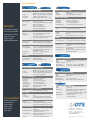
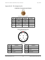
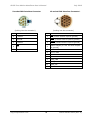
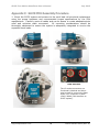
SLICE Free Motion Headform
User’s Manual
July 2012
13000-40180-MAN (Rev. 0)
SLICE Free Motion Headform User’s Manual
July 2012
Table of Contents
DTS Support .................................................................................................... 4
Introducing the SLICE Free Motion Headform (FMH) System .......................... 5
Overview of SLICE FMH System ........................................................................5
13000-20010: SLICE NANO Base (1 each) .....................................................5
13000-20022: SLICE NANO Bridge (1 each) ...................................................5
13000-20090: SLICE FMH Stack Battery (1 each) ...........................................5
SLICE NANO Stack Cover (1 each) and Mounting Screws (2 each) .....................5
13000-30700: SLICE FMH LED Pushbutton Cable Assembly .............................6
13000-30680: Cable, FMH interface to SLICE system (1 each) .........................6
13000-30670: Cable, FMH interface to PC + power (1 each) ............................7
13000-30541: 12 V, 2.5 A power supply (90-240 VAC input) (1 each) ..............7
13000-30120: SLICE 1 Channel Sensor Connector Assembly (3 each) ...............7
13000-30131: SLICE 1 Channel Connector Cable Assembly (1 each) .................7
FMH Skull Cap Plate (1 each) ........................................................................7
Communications..............................................................................................8
Power/Charging Requirements ..........................................................................8
Status LED .....................................................................................................8
Basic Care and Handling ................................................................................. 9
Shock Rating ..................................................................................................9
Mounting Considerations ............................................................................. 10
Thermal Considerations .................................................................................. 10
SLICEWare Software ..................................................................................... 10
Software Installation ...................................................................................... 10
Communicating with the SLICE FMH System ..................................................... 10
How to Auto-Arm the SLICE FMH System ......................................................... 11
Troubleshooting ......................................................................................... 12
Downloading Data ......................................................................................... 12
Viewing Data ................................................................................................ 13
Exporting Data .............................................................................................. 14
Real Time Mode ............................................................................................ 15
Appendix A: SLICE Hardware Specifications................................................. 16
Appendix B: Pin Assignments ....................................................................... 17
13000-30131 Termination Specifications .......................................................... 17
[email protected]
ii
13000-40180-MAN (Rev. 0)
SLICE Free Motion Headform User’s Manual
July 2012
10-pin Interface Connector ............................................................................. 17
5-socket FMH Interface Connector
................................................................ 18
12-socket FMH Interface Connector ................................................................ 18
Appendix C: SLICE FMH Assembly Procedure ............................................... 19
Appendix D: Minimizing System Self-Heating ............................................... 26
[email protected]
iii
13000-40180-MAN (Rev. 0)
SLICE Free Motion Headform User’s Manual
July 2012
DTS Support
SLICE data acquisition systems are designed to be reliable and simple to operate.
Should you need assistance, DTS has support engineers worldwide with extensive
product knowledge and test experience to help via telephone, e-mail or on-site visits.
The best way to contact a DTS support engineer is to e-mail [email protected].
Your e-mail is immediately forwarded to all DTS support engineers worldwide and is
typically the fastest way to get a response, particularly if you need assistance outside
of normal business hours.
For assistance by telephone, please go to
http://dtsweb.com/support/techsupport.php to find the phone number appropriate for
your region of the world.
[email protected]
4
13000-40180-MAN (Rev. 0)
SLICE Free Motion Headform User’s Manual
July 2012
Introducing the
SLICE Free Motion Headform (FMH) System
The SLICE FMH system is a miniature data acquisition system (DAS) designed for
integration into a dummy head. It includes a battery sufficient to run the system for
up to 20 minutes and supports autonomous operation after arming. After the test,
reconnecting the system to a PC and the provided power supply allows data download,
viewing and post-processing, and recharges the battery for the next use.
Overview of SLICE FMH System
A typical 3-channel system is discussed below.
additional channels or custom features.
Your system may vary if you have
Detailed assembly procedures can be found in Appendix C:
Procedure.
SLICE FMH Assembly
Figure 1: 3-channel SLICE NANO Stack for FMH
13000-20010: SLICE NANO Base (1 each)
13000-20022: SLICE NANO Bridge (1 each)
13000-20090: SLICE FMH Stack Battery (1 each)
SLICE NANO Stack Cover (1 each) and Mounting Screws (2 each)
Figure 1 shows a typical 3-channel, SLICE FMH Stack that includes a Base SLICE,
Bridge SLICE, SLICE FMH Stack Battery, stack cover plate, and two M3 x 35 mm or
4-40 x 1-3/8" mounting screws.
Detailed specifications for the Base SLICE and Bridge SLICE can be found on page 16
(Appendix A: SLICE Hardware Specifications) or at www.dtsweb.com . Details on the
SLICE FMH Stack Battery can be found on page 8 (Power/Charging Requirements).
For information on operation of the SLICE system, please see the SLICE User’s Manual.
[email protected]
5
13000-40180-MAN (Rev. 0)
SLICE Free Motion Headform User’s Manual
July 2012
The 12-socket connectors
are functionally identical.
Figure 2: FMH Interface
13000-30700: SLICE FMH LED Pushbutton Cable Assembly
This cable (Figure 3) is used inside the dummy head and connects to the 5-socket
connector shown in Figure 2 and the FMH skull. The pushbutton enables the auto-arm
sequence and the LED provides information on arming status. Additional information
on the LED can be found on page 8 (Status LED); details on arming the system begin
on page 11 (How to Auto-Arm the SLICE FMH System).
Figure 3: 13000-30700 Cable Assembly
13000-30680: Cable, FMH interface to SLICE system (1 each)
This cable is used inside the FMH skull (Figure 4) and connects to either 12-socket
connector shown in Figure 2. It terminates at the inside of the skull cap plate and
mates with 13000-30670.
Figure 4: 13000-30680 Cable Assembly
[email protected]
6
13000-40180-MAN (Rev. 0)
SLICE Free Motion Headform User’s Manual
July 2012
13000-30670: Cable, FMH interface to PC + power (1 each)
This cable (Figure 5) connects to the USB port on your PC and the power supply
provided with your system. It mates with 13000-30680 as it exits the skull cap plate.
Figure 5: 13000-30670 Cable and Interface
13000-30541: 12 V, 2.5 A power supply (90-240 VAC input) (1 each)
A 12 V, 2.5 A power supply (Figure 6) is provided with your system. It will simultaneously charge the battery and power the SLICE FMH system until it is disconnected
prior to the test. Battery capacity and charging requirements can be found on page 8
(Power/Charging Requirements).
Figure 6: 13000-30541 Power Supply
13000-30120: SLICE 1 Channel Sensor Connector Assembly (3 each)
Three, 7-pin, sensor connectors with back shell and ID are provided for use with your
sensors. If not included separately, these are already installed on your sensors.
13000-30131: SLICE 1 Channel Connector Cable Assembly (1 each)
This 7-socket, 50 cm cable assembly is provided to facilitate sensor calibration. It is
provided without terminations to allow the user the option of attaching a connector of
their choice. Sensors can then be disconnected individually from the Bridge SLICE and
calibrated with the use of this cable. A termination drawing can be found on page 17
(13000-30131 Termination Specifications).
FMH Skull Cap Plate (1 each)
This was provided with your Free Motion Headform. You may be provided a new plate
that has been modified to accept cable 13000-30680 (FMH interface to SLICE system)
and to compensate for the added mass of the SLICE FMH system, or your plate may
[email protected]
7
13000-40180-MAN (Rev. 0)
SLICE Free Motion Headform User’s Manual
July 2012
need to be modified. Please contact your SLICE FMH system integrator or FMH vendor
for additional information.
Communications
A USB-to-PC communication and power cable (DTS P/N 13000-30670) is provided with
your system. All communication signals and power/battery charging are supported via
the LEMO interface (Figure 4). Information on installing the software, initializing the
system, downloading and viewing the data begins on page 10 (SLICEWare Software).
Power/Charging Requirements
The SLICE FMH Stack Battery contains an integrated, 8.4 V, 80 mAh, rechargeable
lithium battery sufficient to operate the system for cable-free testing. When the 12 V,
2.5 A power supply is connected to your system, it will simultaneously charge the
battery and power the SLICE FMH system until it is disconnected prior to the test.
Battery life (fully charged)
Up to 20 minutes (full sensor load)
Charge time
~1 hour from complete discharge to
full charge; always charges when
connected to power supply
Charging the system using a maximum of 12 V and without the USB connected
minimizes system self-heating. Additional details can be found in Appendix D.
Status LED
This LED is blue and provides information on arming and recording status. It is on, off
or blinking.
After unit is turned on, LED will blink during sensor warm-up and system arming.
Blinking
ON
OFF
If armed in Circular Buffer mode, the LED will begin recording after sensor warmup and the LED will go solid blue. The LED will also go solid blue in Recorder
mode if the system received a START signal.
If armed in Recorder Mode, the system will stop blinking and go OFF, waiting for
a START signal to begin recording.
[email protected]
8
13000-40180-MAN (Rev. 0)
SLICE Free Motion Headform User’s Manual
Circular Buffer Mode
July 2012
Recorder Mode
(rate increases)
Arming; sensor warm-up (~30 sec)
(LED is ON)
(LED is OFF)
System is recording
Waiting for START signal
(rate steady)
If the LED continues to blink after 45 sec,
the system did not initialize properly.
See page 12 (Troubleshooting).
To arm the system, press and hold the LED pushbutton switch for >3 sec. After 7 sec,
the LED will begin to blink, indicating the system is performing the auto-arm initialization sequence. After 32 sec, the LED will be either on (circular buffer mode) or off
(recorder mode). Note: The SLICE FMH system’s auto-arm feature must be softwareenabled prior to pushbutton initialization. Only Circular Buffer mode is recommended
for use with the FMH. Details on software installation and use begin on page 10
(SLICEWare Software).
Basic Care and Handling
The SLICE FMH system is a high precision measurement instrument, designed to
operate reliably in dynamic testing environments.
Though resistant to many
environmental conditions, care should be taken not to subject the unit to harsh
chemicals, submerge it in water, or use it in a manner inconsistent with its intended
purpose.
The Base SLICE, Bridge SLICE and SLICE FMH Stack Battery are supplied with
calibration data from the factory. DTS recommends annual recalibration to ensure that
the system is performing within factory specifications. SLICE hardware is not userserviceable and should be returned to DTS for service or repair.
Shock Rating
The SLICE FMH system is rated for 500 g, 4 ms duration, in all axes. All mounting
considerations should be thoroughly addressed to ensure the system is adequately
integrated to survive the expected shock loads.
[email protected]
9
13000-40180-MAN (Rev. 0)
SLICE Free Motion Headform User’s Manual
July 2012
Mounting Considerations
To provide the best shock protection, the system should be securely bolted inside the
FMH skull using the proper hardware and recommended torque specifications. Care
must be taken to restrain the cables to permit adequate strain relief and minimal
movement upon impact.
Thermal Considerations
The SLICE DAS is an extremely low power system with negligible self-heating. Should
any self-heating be a concern, this can be addressed by charging the system properly
and minimizing the time it takes to arm the system and perform the test (see
Appendix D). Should you have any questions about using SLICE in your environment,
please contact DTS.
SLICEWare Software
Software Installation
1. Locate the set-up.exe file on the CD or USB drive provided. Double-click the file
to begin the installation and follow the prompts on your screen.
2. When installation is complete, copy the XML file found in the folder “copy
contents to SLICEWare directory after software install ” to the SLICEWare directory.
(The XML file contains the sensor information.) If you were not provided an XML
file, you will have to enter this information later.
3. Start SLICEWare by double-clicking the desktop icon or go to Programs/
SLICEWare.
If you have any
[email protected].
questions
about
software
installation,
please
contact
Communicating with the SLICE FMH System
4. Connect cable 13000-30670 to the LEMO receptacle on the skull cap plate
(Figure 5). Next, connect the cable to the power supply provided (Figure 6) and
your PC. (The SLICE FHM system can be connected to the PC before or after
starting the software.)
5. If you provided your own sensors or had to replace a sensor, you can manually
enter the sensor information into the SLICEWare software before using your
SLICE FMH system. (Check that the sensors that are installed in the FMH are
visible on the
tab. If any sensor is missing, you need to manually
install it.) You will need the calibration data provided with your sensors to do
this. Each sensor must also be assigned to the correct axis and optional ISO
code.
[email protected]
10
13000-40180-MAN (Rev. 0)
SLICE Free Motion Headform User’s Manual
July 2012
How to Auto-Arm the SLICE FMH System
The “Auto-Arm on Boot” feature allows users to automatically arm the system using
user-selected parameters at system power-up/initialization. To use the auto-arm
feature, all DAS in the test must support the auto-arm function.
6. With SLICEWare running and the SLICE FMH system connected (step 4 above),
go to the
working properly.
[email protected]
tab and perform a quick check to verify the hardware is
11
13000-40180-MAN (Rev. 0)
SLICE Free Motion Headform User’s Manual
July 2012
7. Open the
tab. Complete the test set-up information (data collection
mode, length of time, sample rate, etc.).
8. Click the Auto-Arm button. Click OK.
9. Close SLICEWare and disconnect cable 13000-30670 from the skull cap plate.
10.
To arm the system, press and hold the LED/pushbutton switch for >3 sec.
After 7 sec, the LED will begin to blink, indicating the system is performing the
auto-arm initialization sequence. After 32 sec, the LED will be either on
(circular buffer mode) or off (recorder mode).
Troubleshooting
If the LED continues to blink after 45 sec, the system did not initialize properly. To
clear the fault, reconnect the system to the power supply and PC (step 4 above), then
start SLICEWare. Manually arm and test the SLICE FMH system to clear the fault.
(You must clear the fault before the system will power down.) After clearing the fault,
repeat steps 7-10 above.
Downloading Data
1. Reconnect the system to the power supply and PC (step 4 above).
SLICEWare.
2. Open the
set-up, select
Start
tab. To download the total time specified by the initial test
. To download a region-of-interest only, enter the desired
timeframe (for example,
) and then select
.
3. Depending on the length of the test, it may take several minutes or longer to
download the data. A download progress bar is shown in the center of the
screen alongside the corresponding DAS.
[email protected]
12
13000-40180-MAN (Rev. 0)
SLICE Free Motion Headform User’s Manual
July 2012
Viewing Data
1. Open the
tab. Available data sets for viewing are shown on the left.
These data sets are stored on your PC, not the SLICE.
2. Selecting a test will load it in the viewing area.
3. You can zoom using the
can also zoom by selecting
of-interest.
[email protected]
and
icons on the upper right of the screen. You
and then drawing a window around a region-
13
13000-40180-MAN (Rev. 0)
SLICE Free Motion Headform User’s Manual
July 2012
4. Multiple data channels can be viewed on the graph at one time. You can choose
which channels to view using
.
5. The data can be viewed unfiltered or using a selected filter.
Exporting Data
1. Open the
available.
[email protected]
tab and select the data set you wish to export from the tests
14
13000-40180-MAN (Rev. 0)
SLICE Free Motion Headform User’s Manual
July 2012
2. Select an export format for the data.
3. Select whether or not you want the exported data to be filtered or unfiltered. If
filtered is selected, SLICEWare will apply the software filter associated with each
sensor in the test.
4. To export the data using the settings you selected above, select
. A ‘save
as’ dialog will open and allow you to choose where to save the exported data.
Real Time Mode
To view data from the channels real time, click the
tab. You can view any or all
of the three channels. Note that the data is being sampled continuously at a relatively
low sample rate. For example, you may not see a short duration data pulse when
hitting the SLICE against a surface.
[email protected]
15
13000-40180-MAN (Rev. 0)
Specifications
BASE SLICE (MICRO & NANO)
Size:
Weight:
Connectors:
Connectors:
ENVIRONMENTAL
Operating Temp.:
SERVICES
24/7 Worldwide Tech Support
ISO 17025 (A2LA) Calibration
Onsite Calibration & Training
Application Consulting
Software Integration
OEM/Embedded Applications
Humidity:
Shock:
DATA RECORDING
Modes:
Memory:
Sample Rate:
TRIGGERING
Hardware Trigger:
Level Trigger:
MICRO 42 x 42 x 8 mm (1.65 x 1.65 x 0.32”)
NANO 26 x 31 x 6.5 mm (1.02 x 1.22 x 0.26”)
MICRO ~28 g (0.99 oz), NANO ~14.2 g (0.50 oz)
Omnetics, circular locking, 12-pin
MICRO integrated, NANO cable assembly
0 to 60°C (32 to 140°F)
Call to discuss extended temperature ranges
95% RH non-condensing
500 g, 4 msec half sine
5000 g option (SLICE NANO)
50,000 g option (SLICE HG)
Recorder or circular buffer modes available.
7 GB non-volatile flash per SLICE stack
Up to 120 ksps/channel
Individual channel sample rate is determined
by number of SLICEs in each stack
Isolated contact closure & logic-level input
Software programmable from any channel(s)
Power Control:
Protection:
SOFTWARE
Control:
Operating Systems:
Communication:
9-15 VDC; >11 VDC when using BATT SLICE
100 mA. Each additional SLICE unit requires
additional power (depends significantly on
connected sensor load)
Remote power control input for on/off
Reverse current, ESD
SLICEWare, API
Windows® XP/Vista/7
USB; optional Ethernet interface
BRIDGE SLICE (MICRO & NANO)
Size:
Weight:
Connectors:
MICRO 42 x 42 x 7 mm (1.65 x 1.65 x 0.32”)
NANO 26 x 31 x 5.5 mm (1.02 x 1.22 x 0.22”)
MICRO ~25 g (0.88 oz), NANO ~13.8 g (0.49 oz)
Omnetics, circular locking; 3 single-channel
7-pin or 1 three-channel 16-pin
SIGNAL CONDITIONING
Number of Channels:
Input Range:
Bandwidth:
Gain Range:
Auto Offset Range:
Bridge Support:
Shunt Check:
3 differential, programmable
±2.4 V (2.5 V center)
DC to 40 kHz, programmable
1.0-1280, programmable
100% of effective input range
Software switchable completion
Emulation method
ANALOG-TO-DIGITAL CONVERSION
Type:
EXCITATION
Method:
Voltage:
On/Off Control:
TECH CENTERS
Seal Beach, California USA
Novi, Michigan USA
Sydney, Australia
Shanghai, China
Zorge, Germany
Tokyo, Japan
POWER
Voltage:
Current (Maximum):
ANTI-ALIAS FILTER
Fixed Low Pass:
Size:
Weight:
Connectors:
MICRO 42 x 42 x 7 mm (1.65 x 1.65 x 0.28”)
~28 g (0.99 oz)
10-32 coaxial (Microdot-compatible)
SIGNAL CONDITIONING
Number of Channels:
Input Range:
Bandwidth:
Gain Options:
Auto Offset Range:
3
0.5-23.5 V (12 V center)
DC to 40 kHz, programmable
1 or 10, user programmable
100% of effective input range at gain of 1
ANALOG-TO-DIGITAL CONVERSION
Type:
EXCITATION
Method:
Voltage:
On/Off Control:
POWER
Voltage:
Current (Maximum):
16-bit SAR, one ADC per channel
One 2.2 mA constant-current source/channel
up to 24 V
Shut down when not armed or recording
Supplied via BASE SLICE
70 mA with sensors connected to all channels
ANTI-ALIAS FILTER
Fixed Low Pass:
POWER
Supply Voltage:
Current (Maximum):
IEPE SLICE (MICRO Only)
16-bit SAR, one ADC per channel
4-pole Butterworth, standard knee frequency
of 40 kHz
Adjustable Low Pass: 5-pole Butterworth set under software control,
50 Hz to 40 kHz
Overall Response:
Both filters may be used together to achieve
9-pole effective response
ARS SLICE (MICRO Only)
Size:
Weight:
Number of Channels:
Range Options:
Current (Maximum):
ACCEL SLICE (MICRO Only)
Size:
Weight:
Number of Channels:
Range Options:
Current (Maximum):
MICRO 42 x 42 x 9 mm (1.65 x 1.65 x 0.35”)
~30 g (1.06 oz)
3
Triaxial, ±50, 100, 500 g
65 mA (power supplied via BASE SLICE)
BATTERY SLICE (NANO Only)
Size:
Weight:
Charge Status:
Charge Time:
One 20 mA current-limited source/channel
5.0 V
Shut down when not armed or recording
Opt. pulsed excitation for low sampling rates
MICRO 42 x 42 x 9 mm (1.65 x 1.65 x 0.35”)
~30 g (1.06 oz)
3
Triaxial, ±300, 1500, 8k, 12k, 50k deg/sec
75 mA (power supplied via BASE SLICE)
Discharge Rate:
NANO 26 x 31 x 4 mm (1.65 x 1.65 x 0.16”)
~7 g (0.25 oz)
Backup battery charges when input voltage to
BASE SLICE is greater than 11 VDC
~15 min. from complete discharge to full charge
(100 mA at input connector on Base)
~16 seconds at 1 A
~2 minutes at 400 mA
Supplied via BASE SLICE
110 mA with 350 ohm bridges all channels
Power will vary significantly with sensor load
4-pole Butterworth, standard knee frequency
of 40 kHz
Adjustable Low Pass: 5-pole Butterworth set under software
control, 50 Hz to 40 kHz
Overall Response:
Both filters may be used together to achieve
9-pole effective response
SAE J211:
System exceeds SAE J211 response
Diversified Technical Systems, Inc.
Electric Ave., Suite 206
Seal Beach, CA 90740 USA
Phone: +1 562 493 0158
Email: [email protected]
www.dtsweb.com
Specifications subject to change without notice.
SLICE Free Motion Headform User’s Manual
July 2012
Appendix B: Pin Assignments
13000-30131 Termination Specifications
1
2
5
3
6
7
(looking into the connector)
Pin
Wire color
Function
1
Green
+Sig
2
White
-Sig
3
Red
+Ex
4
Yellow
+ID
5
Black
-Ex
6
Shield
-ID/Shield
Notes
Solder bridge on
pins 6 and 7
10-pin Interface Connector
(ECG.1B.310.CLL)
1
8
2
7
9
10
3
4
6
5
(panel view)
Pin
Function
Pin
Function
1
/ON
6
Ground
2
/START
7
USB power
3
/EVENT
8
USB_DP
4
Status
9
USB_DM
5
12-15 VDC
[email protected]
10
17
USB Ground
13000-40180-MAN (Rev. 0)
SLICE Free Motion Headform User’s Manual
July 2012
5-socket FMH Interface Connector
12-socket FMH Interface Connector*
1
5
4
8
3
2
1
3
(looking into the connector)
Pin
4
Function
7
10
11
12
(looking into the connector)
Pin
Function
1
−Status
1
On (contact closure input to ground)
2
Ground
2
Start (contact closure input to ground)
3
+Status
3
Event (contact closure input to ground)
4
On
4
Status output (5 V via 10K with respect
to ground)
5
Event
5
12–15 VDC
6
12–15 VDC
7
Ground
8
Ground
9
USB_PWR
10
USB_DP
11
USB_DM
12
Ground
* These connectors are identical.
[email protected]
18
13000-40180-MAN (Rev. 0)
SLICE Free Motion Headform User’s Manual
July 2012
Appendix C: SLICE FMH Assembly Procedure
1. Mount the SLICE system and sensors to the neck load cell structural replacement
using the proper hardware and recommended torque specifications by the FMH
manufacturer. Carefully route all cables and use tie downs to create adequate strain
relief and minimize cable movement.
All mounting considerations should be
thoroughly addressed to ensure the system is adequately integrated to survive the
expected shock loads.
FMH Interface
The 12-socket connectors are
functionally identical and either
may be used to connect the Base
SLICE “UP” connector or cable
13000-30680 (FMH interface to
SLICE system).
[email protected]
19
13000-40180-MAN (Rev. 0)
SLICE Free Motion Headform User’s Manual
July 2012
2. Attach cable 13000-30680 (FMH interface to SLICE system) to skull cap plate using
the provided hardware. Tighten securely.
[email protected]
20
13000-40180-MAN (Rev. 0)
SLICE Free Motion Headform User’s Manual
July 2012
3. Attach cable 13000-30700 (SLICE FMH LED Pushbutton Cable Assembly) by
threading it into the FMH skull. Tighten securely.
[email protected]
21
13000-40180-MAN (Rev. 0)
SLICE Free Motion Headform User’s Manual
July 2012
4. Insert neck load cell structural replacement into skull. Note the position of the flat
edge relative to the FMH skull.
5. Rotate neck load cell structural replacement counter-clockwise so that the FMH
interface is visible. Connect cable 13000-30700 (SLICE FMH LED Pushbutton
Cable Assembly) to the FMH interface.
[email protected]
22
13000-40180-MAN (Rev. 0)
SLICE Free Motion Headform User’s Manual
July 2012
6. Connect cable 13000-30680 (FMH interface to SLICE system) to the FMH interface
using the available 12-socket connector.
[email protected]
23
13000-40180-MAN (Rev. 0)
SLICE Free Motion Headform User’s Manual
July 2012
7. Rotate neck load cell structural replacement clockwise so that the flat edge of the
neck load cell structural replacement is aligned properly. Secure it to the aluminum
skull using the proper hardware and recommended torque specifications by the FMH
manufacturer.
[email protected]
24
13000-40180-MAN (Rev. 0)
SLICE Free Motion Headform User’s Manual
July 2012
8. Route the cable into the skull and install the skull cap plate using the proper
hardware and recommended torque specifications by the FMH manufacturer.
[email protected]
25
13000-40180-MAN (Rev. 0)
SLICE Free Motion Headform User’s Manual
July 2012
Appendix D: Minimizing System Self-Heating
Following the procedure outlined below will avoid any unnecessary heat generation in
excess of ~1°C.
1. Charge the system using a 12 V power supply. 12 V is the minimum
required by the SLICE system; anything in excess will contribute to heat generation.
2. Do not connect your PC to the system while it is charging. While this
prevents checking system status, continual PC communications keep the microprocessor active. If the battery is not completely discharged and you do not want to
wait the maximum recharge time (1 hour), you may wish to implement a hardware
interface that allows you to check battery charge status. When the input current drops
to 75 mA, the battery is fully charged.
3. Complete the software auto-arm sequence and disconnect the system from
the PC and power supply within 2 minutes. Completing this step quickly minimizes
system and sensor self-heating. Once auto-arm and disconnect are completed, the
system is in a low-power state and awaiting initialization.
4. Initialize the system and perform your test quickly. To initialize the system,
press the LED/pushbutton switch for ≥3 sec. When the LED goes solid, the system is
ready for testing. Performing your test as soon as possible after system initialization
minimizes self-heating.
[email protected]
26
13000-40180-MAN (Rev. 0)
SLICE Free Motion Headform User’s Manual
July 2012
Revision History
Date
By
13 Jul 2012
EKK
[email protected]
Description
Initial release. (Rev 0)
27
13000-40180-MAN (Rev. 0)