1
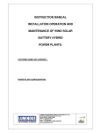
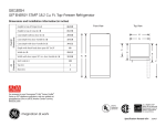
COMMERCIAL / TRUCK
Valve-Regulated Lead-Acid (VRLA):
Gelled Electrolyte (Gel) and Absorbed Glass Mat (AGM) Batteries
TECHNICAL GUIDE
A. How it works
I:
INTRODUCTION TO VRLA
II:
DISTINGUISHING BETWEEN
AGM & GEL
III:
VRLA PRODUCTS AND SERVICE IN
COMMERCIAL VEHICLES
IV:
TESTING CONSIDERATIONS
V:
CHARGING CONSIDERATIONS
VI:
COMMERCIAL BATTERY SYSTEMS
VII: ENVIRONMENTAL TEMPERATURES
& VENTING CONDITIONS
VIII: SAFETY PRECAUTIONS
A VRLA battery utilizes a one-way, pressure-relief valve
system to achieve a “recombinant” technology. This means
that the oxygen normally produced on the positive plate is
absorbed by the negative plate. This suppresses the
production of hydrogen at the negative plate. Water (H2O)
is produced instead, retaining the moisture within the
battery. It never needs watering, and should never be
opened as this would expose the battery to excess oxygen
from the air. In addition to damaging the battery, opening
it also voids the warranty.
B. The difference between VRLA and traditional
flooded batteries
Flooded electrolyte batteries do not have special one-way,
pressure-relief valves, as they do not work on the recombination principle. Instead, flooded designs utilize a vent to
allow gas to escape. They contain liquid electrolyte that can
spill and cause corrosion if tipped or punctured. They
should not be used near sensitive electronic equipment.
They can only be installed “upright.” Flooded batteries lose
capacity and become permanently damaged if:
• Left in a discharged condition for any length of time
(due to sulfation). This is especially true of designs that
require water maintenance.
• Continually over-discharged (due to active material
shedding). This is especially true of commercial starting
types.
I. INTRODUCTION TO VRLA
Valve-Regulated Lead-Acid or VRLA, including Gel and AGM
(Absorbed Glass Mat) battery designs, can be substituted in
virtually any flooded lead-acid battery application (in conjunction with well-regulated charging). Their unique features and
benefits deliver an ideal solution for many applications where
traditional flooded batteries would not deliver the best results.
For almost three decades, East Penn has been manufacturing
valve-regulated batteries using tried and true technology
backed by more than 65 years experience. East Penn produces a complete line of Gel, AGM, and conventional flooded
products for hundreds of applications. This diverse product
offering enables East Penn to be objective as to the advantages of each type of battery. East Penn’s VRLA (Gel and
AGM) products have the reputation of being the highest
quality VRLA batteries available.
II. DISTINGUISHING BETWEEN AGM AND GEL
A. AGM (Absorbed Glass Mat) batteries
The electrolyte in AGM batteries is completely absorbed in
separators consisting of matted glass fibers. This causes
them to be spillproof, meaning they don’t leak acid like a
flooded design if tipped on their side. The glass mats in
AGM batteries are wrapped around the positive plate, which
helps prevent damage from vibration and extend cycling.
The battery’s groups are packed tightly in the case partitions
also protecting its power producing components. AGM battery designs can have over twice the cycle life of a
conventional flooded product.
B. Gel or Gelled Electrolyte batteries
F. Can I mix VRLA and Flooded batteries within
the same battery pack?
The electrolyte in a Gel battery is permanently locked in a
highly viscous gelled state instead of the traditional liquid
form. Because there is no liquid-type electrolyte, it will not
leak out of the battery if tipped on its side. The thick, gelled
electrolyte and tightly packed groups also protect the battery’s power producing components. Gel battery designs
have a superior deep discharge resiliency and can deliver up
to three times the cycle life of an AGM product
No, you cannot mix AGM, Gel, and flooded batteries within
the same battery pack. Batteries should be paired together
with other batteries of similar age and ratings within the
same battery pack.
III. Properties of VRLA Products and
Service in Commercial Vehicles
C. Why use an AGM Battery for Commercial truck.
AGM batteries offer superior starting power, high reserve
capacity, and long lasting life. The advanced AGM technology and all-purpose design makes East Penn’s AGM battery
excellent for quick starts, extended cycling, and deep cycle
use like powering accessories and cabin features when the
engine isn’t running. East Penn’s heavy cycling AGM batteries are especially designed for the heavy demand of battery
powered HVAC systems. All group 31 AGM batteries have
the same case/cover configuration as a traditional group 31,
which allows it to securely fit and be compatible with existing holddowns. A spillproof construction and minimized
gassing makes them safe to use in the driver’s compartment or near sensitive electronic equipment. In addition,
this reinforced AGM construction further extends battery life
by withstanding the added vibration typical of commercially
used vehicles.
Today’s commercial applications are being integrated with
more electronic and accessory power demands than ever
before. New advances in the vehicle’s electrification and
battery-powered controls are requiring a greater demand
on the batteries’ functions in the vehicle. Independently
powered HVAC and APU systems require a deeper cycle
service that also differs from the predominate starting
service of traditional battery designs.
In most cases, it is not enough to just meet the commercial
vehicle’s starting requirements. Understanding the cycling
or deep cycle demands placed on the battery as well as the
individual user’s needs is extremely critical. VRLA batteries
can provide solutions to these additional requirements on
the battery, and it’s extremely important to understand how
they can benefit the many functions batteries serves in
today’s commercial vehicle electrical systems.
D. Why use a Gel Battery for Commercial truck.
A. Starting Service
New heating and cooling systems for commercial trucks
need a battery with tremendous deep cycle capabilities.
HVAC and APU systems require plenty of power dedicated
solely for their use. Gelled electrolyte designs are the deepest cycling batteries withstanding multiple charging and
recharging in order to provide the continual service
demanded by these systems. These maintenance-free batteries are designed to deliver dependable performance cycle
after cycle while providing longer battery life. Their spillproof design and minimized gassing makes them safe to
use in the driver’s compartment or near sensitive electronic
equipment. In addition, the gelled electrolyte withstands the
added vibration of commercially used vehicles extending
battery life.
The predominate function that batteries serve in commercial
vehicles is to start the vehicle. However, there are other
demands that today’s battery must withstand in order to
continue to provide that service. VRLA batteries offer a
durability-enhanced design that reinforces the battery so it
can continue to deliver dependable starting power, even
under demanding auxiliary loads. While the battery’s durability is becoming more and more important, it does not
negate the fact that the batteries must meet or exceed the
vehicle’s Cold Cranking requirements.
Cold Cranking Amps (CCA) is a measure of engine starting
ability based on being able to sustain a minimum voltage
(7.20) under load for a minimum time period (30 seconds)
at a temperature of 0°F. The test is done on a new fully
charged battery. Regardless of the actual low temperature,
typical cranking duration, minimum acceptable voltage, and
lowest expected state of charge; engine manufacturers set
their battery requirements relative to this standard reference
value. CCA is also measured by some battery testers. Here it
is a calculated value proportional to battery conductance
and not the results of a standard test.
AGM batteries excel for high current, high starting power
demanding applications, especially in extremely cold environments. Gel battery power declines faster than an AGM
battery, especially as the temperature drops below 32ºF
(0ºC). They can be used for starting if the battery meets the
CCA requirements of the vehicle, but are usually recommended for deep cycle use.
E. Major difference between Gel and AGM battery
performance
A Gel battery is better suited for super-deep discharge applications, which means it can withstand deeper discharges
without damaging the battery’s performance. However, due
to the physical properties of the gelled electrolyte, Gel battery power declines faster than an AGM battery as the
temperature drops below 32ºF (0ºC). AGM batteries excel
for high current, high power applications and in extremely
cold environments. AGM batteries deliver a better dual purpose solution for a combination of starting and accessory
power.
2
B. Cycle Life
SAE J2185 Testing Cycling and Starting Performance
(Graph represents general criteria of this test and is not
showing results of a particular battery.)
Cycle life is how many times you can discharge a battery
and recharge the battery again before it degrades to the
point it is no longer usable. A battery with extended cycle
life survives longer than average under the more grueling
demands of less than ideal environments and tough
commercial use. This includes warmer climates, higher
temperature environments, longer than typical hours of
usage, higher annual miles of operation, and frequent
electrical loading while the engine is off.
The appropriate test for cycle life depends on how the
battery is going to be used. As a general rule, high
temperature accelerates aging and deeper discharging
accelerates capacity degradation giving fewer cycles.
Different tests have different definitions of end of life.
Some users may be able to tolerate more degradation.
If the battery is undersized for its duty, a user may experience problems before the defined end of life. It’s important
to remember that if you use energy, you must replace it all,
plus an allowance for inefficiency. If you add extra loads to
a vehicle, the charging system may be too small to recharge
in the time available.
SAE J2185 Life on Various Batteries
700-760 CCA Ratings
1. Cycle life testing
Good cycle life performance depends on the criteria of the
test. For example, if one test shows a battery can perform
1000 cycles, that could be good or bad depending on the
test’s criteria. 500 cycles might be an excellent performance
on one test but on another test 500 cycles might indicate
poor performance.
The SAE J2185 is a popular test to determine the effects
that cycling will have on the battery’s starting performance.
A 25-amp, 1-hour discharge is used to mimic the key-off
loads at 122°F. The recharge is accelerated to 2.5 hours.
After 26 cycles, there is a rest and a 50-second cranking
simulation. The battery could fail during the 25-amp discharge, but in practice, the cranking simulation is the typical
point of failure. A single 25 amphere-hour cycle could
represent one day of service in a vehicle with excessive
hotel loads, or it could represent over a week of loads in a
day cab vehicle.
The fact that this is an individual battery test should be
considered when evaluating the three or four battery system
typical in many commercial trucks. In these systems, a
single battery is supplying one-third or one-fourth of the
vehicle’s needs.
2. Depth of Discharge and Cycle Life
Depth of discharge will affect cycle life. The harder any
battery has to work, the sooner it will fail. The shallower
the average discharge, the longer the life.
It’s important to size a battery system to deliver at least
twice the energy required, to assure shallow discharges.
Follow these tips for the longest life:
• Avoid ultra-deep discharges. The definition of ultradeep discharge may vary with application and battery
type.
• Don’t leave a battery at a low stage of charge for an
extended length of time. Charge a discharged battery
as soon as possible.
• Don’t cycle a battery at a low state of charge without
regularly recharging fully.
• Use the highest initial charging current available (up to
30% of the 20-hour capacity per hour) while staying
within the proper temperature-compensated voltage
range.
C. Battery Capacity and Discharge Rates
Battery capacity is related to runtime at a fixed rate and
temperature. It has units that are the product of current
multiplied by time (such as ampere-hours). The amperehour is a unit of “charge”.
3
The typical vibration test for on-road trucking applications
was a test adopted from the SAE off-road work machine
battery standard. This SAE J930 Level 2 test is an 18-hour
test at 5.0 peak G-force on the vertical axis at 30-36Hz. TMC
RP-125 describes the same test. This test consists of about
2.2 million upward motion reversals and 2.2 million downward motion reversals where each reversal of direction
requires the battery to absorb a force of 5 times its own
weight. Metals will eventually break from fatigue. Holes can
be rubbed through separators or the separators can move
out of position. A battery that can survive this severe test is
extremely unlikely to suffer degradation from vibration from
typical road use in its service lifetime. East Penn’s VRLA
products are especially designed to withstand the affects of
vibration as seen from the results of utilizing these vibration
tests.
Capacity is often defined on the basis of a 20-hour runtime.
If the 20-hour capacity is 100 ampere-hours, the typical new
fully charged battery can deliver 5 amps for 20 hours at the
standard temperature (80°F) to the standard cutoff voltage
(10.50 volts under load). Reserve capacity is the minutes
of runtime under a 25-amp load.
The relationship between capacity and discharge rate is
shown by Peukert’s curve. The faster you discharge, the
fewer ampere-hours you will get. Some chargers and battery monitors may request “Peukert’s coefficient”. The
following graph represents EPM AGM commercial batteries.
The Effects of the Speed of Discharge on
Available Capacity
Typical Peukert Relationship (EPM AGM)
Speed of Discharge Versus Available Capacity
1. Proper mounting is important.
If the battery can bounce, slide around, or if the mounting
system can flex excessively, on the road failure is possible –
even with a vibration-resistant VRLA design. The vehicle
manufacturer and end user are responsible for correct
mounting. Properly mounting and/or securing each individual battery is one of the best ways to prevent the batteries in
a system from excessive vibration and damage.
IV. TESTING CONSIDERATIONS OF
VRLA DESIGNS
1. Capacity varies with temperature.
For cycling service, if the discharge rate is low, the reduction rate for temperature is approximately 0.5% per 1°F.
If you know the capacity at a specific discharge rate at 80°F,
you should expect approximately the following at lower
temperatures:
• 90% at 60°F
• 80% at 40°F
• 70% at 20°F
A. Preparing for Testing and Charging
It is important to follow all BCI (Battery Council
International) safety instructions for working around batteries, handling batteries, and charging batteries for you and
all bystanders.
For starting service, the reference is to CCA at 0°F.
If you know the current the battery can support for 30 seconds at 0°F, you should expect the battery can support the
following at varying temperatures:
• 80% of that current at -20°F
• 125% of that current at 32°F
• 140% of that current at 80°F
D. Vibration Resistance in VRLA Design
California
Proposition 65
Warning
Vibration resistance is extremely important to battery life in
almost any application, but especially in a commercially
used vehicle and equipment that undergoes long hours of
continual use. The glass mats in AGM batteries are wrapped
around the positive plate, which helps prevent damage from
vibration. In a gel design, the thick, gelled electrolyte and
tightly packed groups protect the battery’s power producing
components from vibration.
Batteries, battery posts, terminals and related accessories
contain lead and lead compounds, and other chemicals known to
the state of California to cause cancer and birth defects or other
reproductive harm. Wash hands after handling.
1. Visually inspect each battery for damage. Do not charge or
test a damaged battery. Remove from service.
2. Inspect vehicle. Repair or replace ineffective hold-downs.
Clean connections and terminals as needed. Replace
damaged wiring.
4
V. CHARGING CONSIDERATIONS
OF VRLA DESIGNS
3. Group 31 battery studs must not be used for testing or
charging connections. Install adapters. The adapters must
be tight against the lead “button” at the base of the stud.
Alternatively, you may clamp directly to the sides of the lead
button. Both sides of both clamps must make good electrical contact with the lead button.
4. Be sure to use the CCA rating for a handheld tester or
calculate the load for a load tester. Other ratings are often
also displayed. Using the wrong expectations could lead
to incorrect results.
In the rare occurrence that a VRLA battery needs to be
charged outside of the vehicle’s charging system, there are
numerous chargers that can be used. Many common battery chargers are not fully compatible with VRLA batteries,
however; if the voltage does not exceed 15.4 volts at any
time they will not harm the battery if used only once or
twice over the battery’s lifetime.
B. Evaluating the battery condition of a
charged battery
Adversely, not all chargers are compatible. Some can
produce severe battery damage in only a few hours of use.
Large “wheeled chargers” that are found in many shops
must be avoided unless a 15.4 voltage limit is maintained.
It is recommended that testing should not occur until at
least 4 hours have passed since the battery was charged.
Resting the battery minimizes the occurrence of good batteries being called “bad” and bad batteries being called
“good.” The battery must be disconnected. (Some chargers
continue supplying a maintenance charge while indicating,
“done.”) A handheld conductance tester’s accuracy can be
diminished when testing a battery that was recently
charged. Resting also gives a better indication of battery
shorts.
A. Ideal Charging Parameters
East Penn recommends the following charging parameters
be used for its AGM and Gel VRLA product to optimized the
battery’s performance and life:
• Charge/Absorption/Equalize Between
13.8 – 14.6 Volts @ 77°F (25°C)
• Float/Standby Between 13.4 – 13.6 Volts @ 77°F (25°C)
• Temperature Corrected Charging Required
C. Testing options
• BCI load test—Using a carbon pile or similar discharging
device, load the battery at 1/2 of the CCA rating. Note voltage at 15 seconds and stop discharge. If voltage is less
than 9.6 (normal temperature), replace battery.
• Fixed load test—Similar to BCI test except voltage limit
depends on CCA rating. See instructions or meter for
details. If tester can do both 6-volt and 12-volt batteries,
be careful of 12-volt batteries that fall into the “good” 6volt battery range. These are bad.
• Handheld conductance tester—Since AGM and Gel
batteries have lower internal resistance than traditional
lead acid batteries, they require electronic testers that are
programmed specifically for them. Many older-model
battery testers cannot adequately test AGM and
Gel batteries.
B. Verify that a charger/setting is acceptable:
Avoid high voltage. If there are multiple settings on a
charger, each setting must be evaluated separately.
• Check voltage a few minutes after charging begins and
periodically during charging. As the battery charges, the
current will fall and the voltage may rise. It must not
exceed 15.4 volts (please note: this voltage limits falls
outside of the recommended charging parameters but
should not damage the battery if the battery only has to
be recharged outside of the vehicle’s voltage-regulated
system a few times.)
• If a charger/setting has been verified to not exceed 15.4
volts to a low current, the charger/setting is acceptable.
(You don’t need to watch the voltage every time.)
D. BCI and Fixed Load Test Procedure
% CHARGE
100
75
50
25
0
C. Determining Required Charging Time
of VRLA Batteries
OPEN CIRCUIT VOLTAGE
VRLA
12.8 or higher
12.60
12.30
12.00
11.80
TYPICAL CHARGING TIME (HOURS) FOR SINGLE BATTERY
CHARGERS MAXIMUM RATE
OCV
SOC
30 AMPS
20 AMPS
10 AMPS
12.80 100%
0.0
0.0
0.0
12.60 75%
0.9
1.3
2.5
12.30 50%
1.9
2.7
5.1
12.00 25%
2.9
4.3
7.8
11.80
0%
4.0
5.7
10.7
1. Recharge if the OCV is below 75% state of charge (Refer to the chart
above). Use a voltmeter to determine the OCV.
2. If you have an adjustable load meter, set the load for 1/2 the CCA rating.
3. Apply the load for 15 seconds. Battery should maintain a voltage greater
than 9.6 volts at 70°F while load is applied.
4. If below 9.6 volts at 70°F, recharge and repeat test.
5. If below 9.6 at 70°F volts a second time, condemn and replace the battery.
*OCV (open-circuit voltage) may be elevated by recent charging activity or
depressed by recent discharging activity. This affects the accuracy of
the SOC (state of charge) estimate.
5
2. Solutions
• Charge the battery on a wheel charger. Charge until the
current has a reading above zero. Then charge 10 to 20
minutes (at the most) longer. Return battery to an automatic charger. Avoid extended charging beyond
20-minutes as it could cause permanent damage to a
Valve-Regulated product.
• Charge the battery with a second good battery connected
in parallel. The second battery should be at least a little
discharged so that it is not also seen as being “full” almost
right away.
The Typical Charging Time for Single Battery chart is
designed to give approximate times for charging and should
not be the deciding factor as to whether the battery is finished charging. An automatic charger compatible with the
battery will look at how the voltage and/or current varies
over time to determine the battery's state of charge . If
charging is stopped prematurely, the battery will appear to
be fully charged; however, this is just the elevated voltage
from the recent charging activity. A much longer charging
time than shown will not harm the batteries if using an
appropriate voltage regulated charger.
The required charging time is often much longer than most
people realize. “Charge” is measured in ampere-hours (Ah).
A typical Group 31 battery holds 85 to 105 ampere-hours
from “full” to “empty” (This is the 20-hour capacity rating).
An overdischarged battery is less than empty. Charging is
never 100% efficient. You normally need to add an extra
8-15% beyond what was removed.
E. Undercharging is Harmful
In many respects, undercharging is as harmful as overcharging. Keeping a battery in an undercharged condition
allows the positive grids to corrode and the plates to shed,
dramatically shortening life. Also, an undercharged battery
must work harder than a fully charged battery, which contributes to short life as well. An undercharged battery has a
greatly reduced capacity. It may easily be inadvertently
over-discharged and eventually damaged.
1. Determine if the battery is half discharged,
fully discharged, or over-discharged.
a. Example: an 85 ampere-hour battery, totally discharged:
you need to supply 85Ah x (100% discharged) x (115%
efficiency factor) = 97.75Ah. You need to supply about
100Ah to recharge completely.
b. To supply 100Ah, you could supply 5 amps for 20 hours,
10 amps for 10 hours, 20 amps for 5 hours, etc.
A charger does not deliver its maximum current the whole
time. When the battery approaches full charge, the charger
limits the voltage by reducing the current. Consequently, a
full charge takes about 3.5 more hours than the calculation
above suggests.
With an automatic charger, charge until the charger indicates that charging is complete. If you are attempting to
charge an overdischarged battery, review the next section.
VI. COMMERCIAL BATTERY SYSTEMS
East Penn has developed the ultimate AGM and Gel battery
technology to deliver both starting and accessory power. In
conjunction with a Low Voltage Disconnect, these batteries
provide the most powerful, reliable, versatile, and efficient
power solutions in the commercial industry.
A. Traditional Battery Systems
A Traditional System is comprised of two to four batteries
with sufficient total CCAs to meet engine starting requirements. If the vehicle has significant hotel or other key-off
loads, cycling batteries (dual purpose) are needed for
good life as well as sufficient CCAs. An automatic LVD
(Low Voltage Disconnect) is recommended for starting
reliability and battery protection where key-off loads may
not leave sufficient power for starting. The alternator
ultimately generates all the electrical energy used by the
vehicle. The alternator must be large enough to restore
the energy used from the batteries in a typical day’s
running period.
D. Handling Problems with Automatic Chargers
and Over-Discharged Batteries
(Note: These issues and solutions are not strictly limited
to VRLA designs)
1. Issues
• 12-volt batteries should never be discharged to less than
10.5 volts under load. Batteries as low as zero volts can
often be recharged and be acceptable for returning to
service.
• To prevent sparking and avoid problems associated with
reversed hookups, many charger leads will not function
until the charger senses a minimum voltage. If the voltage
is too low, the charger will never turn on and no charging
will ever occur.
• An automatic charger is expecting current acceptance to
fall to a low value as the battery approaches a full state of
charge. An over-discharged battery may have very low
initial current acceptance. This can fool the charger into
thinking the battery is “full”. The charger will often indicate
“full” and reduce the charging voltage to a subsistence
level that will be ineffective.
B. Advanced Battery Systems
An Advanced System is needed where key-off electrical
energy needs are high. A pack of auxiliary batteries is added
to support these additional demands. Since these batteries
are not used for cranking, they can be discharged more
deeply. Since loads can be removed from the starting pack,
the starting battery pack can be optimized for the starting
duty. An automatic switch joins the packs for charging. The
charging system(s) must be large enough to handle the
total energy needs in the time available. LVDs are needed
for battery protection if not part of the auxiliary loads.
6
VII. ENVIRONMENTAL TEMPERATURES
AND VENTING CONDITIONS
C. The Use of a Low Voltage Disconnect (LVD)
LVDs are typically found in sleeper cab applications. The
LVD limits discharging by hotel loads so that you can start
the next day. They have a fixed set point typically between
11.7 and 12.1 volts. Unlike a standard life cycle, since loads
and temperatures vary, an LVD does not shut off at a consistent depth of discharge. The State Of Charge (SOC) at a
particular voltage depends on discharge rate and temperature. An LVD can be progressive, shutting down less critical
loads first. If the discharge is continued this will produce a
lower SOC than a single step with the same final voltage
setting. An LVD must not shut down safety-related loads so
significant loads can continue after the last stage of the LVD
is triggered.
A. High Temperature Environments
High temperature accelerates aging and other forms of
degradation. You should avoid exhaust systems, radiators
and other sources of heat. The battery can also generate
heat internally. To dissipate this heat, there should be good
airflow through the battery box and space should be left
between the batteries. The ideal charging voltage varies with
temperature, but most vehicle charging systems deliver the
same voltage at any battery temperature. According to SAE
J930, battery temperatures should not exceed 52°C (125°F)
during normal machine operation.
D. The Use of an Inverter
B. Venting Conditions
An inverter can turn 12V DC battery power into 120V AC
power normally found in homes. The load on the batteries
is determined by the size of the 120V loads being operated.
This can be much less than the watt rating of the inverter.
Inverters have some inefficiency. They may draw some
power continuously when the connected load is zero. They
lose 10-15% or more in the conversion process. The vehicle
manufacturer’s recommendations should be followed when
installing inverters. An inverter typically has a built-in LVD.
The set point is typically not appropriate if the same batteries are used for engine starting.
Lead-acid batteries, including valve-regulated types, emit
hydrogen during normal use. The rate can become quite
high in an overcharging situation. The batteries must not be
charged in a sealed container to prevent hydrogen from
reaching a flammable concentration within the container.
These potentially explosive gasses must be allowed to vent
to the atmosphere and must never be trapped in a sealed
battery box or tightly enclosed space!
Some vehicle makers are installing AGM batteries in the
cabin. The minimum airflow needed to maintain a safe
hydrogen concentration for VRLA batteries is not very high.
Cabins are not hermetically sealed; however, they do vary
in terms of venting requirements and air flow in each individual cabin type should be taken into consideration. Most
vehicle makers have chosen to add a tube to direct any
vented gasses directly outside.
7
B. Procedures
VIII. SAFETY PRECAUTIONS FOR
VRLA BATTERIES
Consult user manual of specific application for safety &
operating requirements. The following safety procedures
should be followed during installation: (Always wear safety
glasses or face shield.)
1. These batteries are sealed and contain no free flowing
electrolyte. Under normal operating conditions, they do
not present any acid danger. However, if the battery jar,
case, or cover is damaged, acid could be present.
Sulfuric acid is harmful to the skin and eyes. Flush
affected area with water immediately and consult a
physician if splashed in the eyes. Consult MSDS for
additional precautions and first aid measures.
2. Prohibit smoking and open flames, and avoid arcing in
the immediate vicinity of the battery.
3. Do not wear metallic objects, such as jewelry, while
working on batteries. Do not store un-insulated tools in
pockets or tool belt while working in vicinity of battery.
4. Keep the top of the battery dry and clear of all tools and
other foreign objects.
5. Provide adequate ventilation and follow recommended
charging voltages.
6. Extinguishing media: Dry chemical, CO2, water and foam
extinguishers.
7. Never remove or tamper with pressure-relief valves.
Warranty void if vent valve is removed.
Although all valve-regulated batteries have the electrolyte
immobilized within the cell, the electrical hazard associated
with batteries still exists. Work performed on these batteries should be done with the tools and the protective
equipment listed below. Valve-regulated battery installations should be supervised by personnel familiar with
batteries and battery safety precautions.
A. Protective Equipment
To assure safe battery handling, installation and maintenance, the following protection equipment should be used:
• Safety glasses or face shield (Consult application specific
requirements)
• Acid-resistant gloves
• Protective aprons and safety shoes
• Proper lifting devices
• Properly insulated tools
East Penn Manufacturing Co.
Lyon Station, PA 19536-0147
Phone: 610-682-6361
E.P.M. Form No. 2007 10/13
© 2013 by EPM Printed in U.S.A.
Fax: 610-682-4781
www.eastpenn-deka.com
All data subject to change without notice. No part of this document may be copied or
reproduced, electronically or mechanically, without written permission from the company.