1
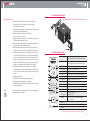
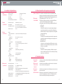
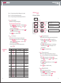
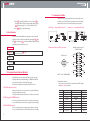
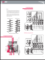
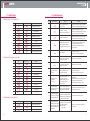
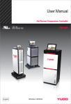
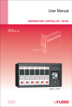
User Manual
English
<< Stand type
HEAD OFFICE & FACTORY
1112, Seohae-Ro, Paltan-Myeon, Hwaseong-City, Gyeonggi-Do, 445-915 Korea
Tel. + 82 31 350 2530 (Overseas Sales Team) Fax. + 82 31 354 7446
E-mail. [email protected] Web. www.yudo.com
Ver. 2.0 MN CW 662 [ 15. Mar ]
▶ We reserve the right to change specifications without notice.
CONTENTS
1. Inspection and Operation
Thank you for using YUDO product.
Please read this manual carefully before you use YUDO product.
You can contact YUDO Headquarters for technical advice.
02
1) Product Check
2) Safety Precautions
3) Operating Procedure
05
2. Structure of Controller
3. Name of Components
4. Controller Unit Specifications
05
06
1) Input specifications
2) Output specifications
3) System specifications
4) Environment specifications
5. Outline of controller and temperature control method
07
1) Outline of Controller
2) Temperature Control Method
07
08
6. Protective Functions
7. Operation Mode
1) Operation Mode Selection
2) Display Change
09
8. Menu Setting
1) User’s Setting Menu (
2) Supplier’s Setting Menu (
3) Edit Menu (
)
)
)
9. Reset Function
10. Integrated Control Function (Optional)
11. Connector and Cable
20
20
21
1) How to wire heater and T/C in connectors
(1) Standard Specifications
(2) Options
12. Diagram for Unit and Structure
13. Electric Wiring Diagram
22
23
1) 220V (3 Phases 3 Lines Type)
2) 380V (3 Phases 4 Lines Type)
3) 220V (1 Phases 2 Lines Type)
14. Wiring Modification Method
24
1) Wire modification method from 3 phases 3 lines 220VAC to 3 phases 4 lines 380VAC
2) Wire modification method from 3 phases 4 lines 380VAC to 3 phases 3 lines 220VAC
15. Default Values
26
1) Default value for user’s menu
2) Default value of supplier’s menu
3) Default value of edit menu
16. Troubleshooting
27
01
1. Inspection and Operation
Please read through this instruction manual carefully to prevent any problems from misuse of
the product. Please make this manual readily available to the final operator.
ᆞThis instruction manual may change without notice.
ᆞPlease contact YUDO for any questions or problems regarding the product
or this instruction manual.
ᆞIt is illegal to copy this instruction manual without permission.
1) Product Check
Caution
Please check if the product matches the product description you ordered.
Please look for any damages or defects.
Please contact YUDO if any problems are discovered.
2) Safety Precautions For safety, please use the product as instructed by this manual. Please
comply with cautions mentioned below because they are very important
for safety. Safety cautions consist of danger!, warning!, and caution!
This instruction manual contains two types of safety notices, Warning!
and Caution! YUDO is not responsible for any injuries/damages done
by negligence or by not following the instruction manual.
Danger
(1) Please do not touch input terminals by any part of body or a conductor
of electricity. It may cause electric shock.
(2) Do not use if the power cable is damaged.
Warning
(3) Be sure that the input power is rated and sequence of phases is
correct in order to prevent from damage or fault.
(4) Please do not supply power to the controller before complete the
wirings in order to prevent from electric shock or damage.
(5) Please do not install or store on places with flammable substance or
explosive gas because this is not explosion proof.
(6) Do not allow any screw, metal material, water, oil, etc. to go inside of
controller.
(7) Please do not modify or add components to the product.
It may cause malfunction, electric shock, or fire.
(8) Please power off before installation or dismantling.
It may cause electric shock, malfunction, or fault.
(9) Check that earth/ground connection is in good condition.
(earth/ground connection is to prevent from electric shock.
Please comply with this for safety.)
02
Safety marks
(10) We reserve the right to change this instruction manual without notice.
(11) Please check if the product matches the product description you ordered.
(12) Please look for any damages or defects which can be caused
during transportation.
(13) Install controller in upright position.
(14) Please do not install or store on places exposed to direct shock or
mechanical vibrations.
(15) Please do not install or store in dirty, oil, chemical, steam, iron
(contamination leve 1 or 2).
(16) Do not clean the controller by agents such as alcohol, benzene, etc.
(17) Please do not install or store on places with high electromagnetic
interference.
(18) Warm up the controller for more than 30 minutes if it’s below 10℃.
(19) Do inspect the controller carefully when it gets wet because it may
cause electric leakage or fire.
(20) Noise filter is recommended if power source generates noise.
(21) Do connect the wirings after confirming the polarity of terminals.
(22) Periodic maintenance is recommended to use this controller safely.
(23) The components of this controller consist of consumable parts and
warranty parts.
(24) The warranty period of this controller including components is
one (1) year in case of general use.
Marks
Description
Protective Earth/ground
Danger Electric Shock Risk
Notice a high temperature
03
2. Structure of Controller
▶Installation Condition : The bottom side is blocked for the safety.
3) Operating Procedure
(1) Check all of the cable connections of the mold (if required).
Be sure that all of the cables are free from wear of damage.
Check the thermocouple type.
(2) Check wiring standards whether Yudo standard (power and thermocouple
combined type) or DME standard, etc.
(3) Check power/thermocouple cable specifications.
(connector size, number of pins)
(4) Using an Ohmmeter, check the resistance and isolation of power cables.
Check the open thermocouple cables.
(5) Connect power/thermocouple cables to the mold only after the mold
is loaded on the injection molding machine.
(6) Check the main input power disconnect to be sure it is in the OFF
position prior to connection of the controller to the power source.
(7) Connect the controller to the power source if the power source and
controller’s main input power are same. (Controller’s main input power
is shown on the label on the backside of controller cabinet. If you find
the differences between actual main input power and power shown on
the label, contact an authorized representative. Unless, it may cause
damage to controller units and/or malfunction of controller.)
(8) Check that the earth/ground connection is in good condition.
Ensure that the system and the mold have the same ground reference
* (Unless, noise may cause damage to fuse and/or triac, and it may cause
injury.)
(9) Switch the controller on.
(10) Switch the controller unit on by pressing the button.
(11) Enter the target temperature (SV : setting value).
(12) Verify whether the actual temperature (PV : point value) reach to the
target temperature (SV).
Caution
If the fan of backside of controller stops, it may cause the unit damaged.
Please confirm the fan is working.
3. Name of Components
1. PV FND
Displays Measured Temperature
(Red 4 Digit-Position Value)of Hot Runner System
2. SV FND
Displays the Set Temperature
(Green 4 Digit-Set Value)of Hot Runner System
3. ℃/℉ LED
Temperature unit Setting value display
4. SOFT LED
Displays SOFT START operation
5. OUT LED
Displays Power Output State
6. J/K LED
Termocouple type (TC) Setting value display
7. AUTO LED
Displays Auto Mode is selected
8. STANDBY LED
Displays Standby Mode is selected
9. MANUAL LED
Displays Manual Mode is selected
10. MODE
Operation switch, User Mode operation key
11. ▲
Value Increase Key
12. ▼
Value Decrease Key
13. SET
Changing cipher key
Supplier's Menu
*SET+MODE
14. SEL/SAVE
Select mode (AUTO, STANDBY, MANUAL) &
save the changes
15. Handle
16. Power Switch
17. Lock Bolt
※Caution. Keypad is made of Silicon rubber.
Don't touch the keypad by Drill, Ballpoint pen and the sharp edged things.
04
05
4. Controller Unit Specifications
1) Input
Specifications
2) Output
Specifications
3) System
Specifications
4) Environment
Specifications
■ Thermocouple Type
■ Control Range
■ Scan Rate
■ Scan Accuracy
■ Compensable Temperature Variation
■ Transmission Output
■ Output Mode
■ Output Resolution Limit
TC-K (IEC-584), TC-J (IEC-584)
40 ~ 400℃
200 mS
±0.5% of F/S
±2.0℃(-15℃ ∼ 65℃)
■ Period of renewal
15A(Max 16.5A), 1 zone/Unit
Phase Control, Zero Cross Control
Phase Control : Approximately 1000 Resolution
Zero Cross Control : 60Hz/50Hz-120/100 Resolution
200 mS
■ Input
Disconnection Detection
Up Scale action, and exceeding ±5% of input range
■ Output
Output Mode
Display Range
Phase Control, Zero Cross Control
40 ~ 400℃
■ Control
Control Method
P BAND
I TIME
D TIME
Hysteresis Range
Self Tuning
PV Preceding Derivative PID
0~ 600.0℃ (at 0, output changes between On and Off)
0 ~ 600.0 Sec
0 ~ 600.0 Sec
0.1 ~ 5.0℃
Quick Auto Tuning , Full Auto Tuning
■ Alarm
Range
Alarm Type
± 99.9℃ of Set Value (SV)
Alarm high, Alarm low
■ Running the controller
RUN
STANDBY
MANUAL
Auto run
Duration, Target temperature
Change input (PV) and output
■ Operating Temperature
■ Operating Humidity
■ Storage Temperature
■ Insulation Resistance
■ Withstand Voltage
■ Vibration Resistance
■ Impact Resistance
■ Warming-up time
06
5. Outline of controller and temperature control method
0℃ ∼ 50℃
20 ~ 90%RH(Non-condensing)
-25℃ ~ 70℃
500Vdc, over 20MΩ (Input Power-F/G, Input/output-F/G)
1,500Vac, 50/60Hz 1 min
(Input power-F/G, Input/Output-F/G, Input/Output-Input Power)
10 ~ 55Hz, bandwidth 0.75mm, X,Y,Z (3) directions 3 swings, 5 min/swing
100 ㎨, X,Y,Z (3) directions 3 times
over 30 min
1) Outline of Controller The controller is a device that has a function to maintain the desired
2) Temperature
Control Method
temperature consistsently by sening the state of hot runner system with
high-intellectual computer system named CPU and input proper power.
(1) Temperature range : 40℃ ~ 400℃ / 104℉ ~ 752℉
(2) Calibration of temperature deviation : It can calibrate the difference
between actual and setting temperatures manually.
(3) Temperature control by : Auto Tuning , Auto PID, Manual PID control,
On/Off control
① Auto Tuning
Is a function to extract the control constant through analyzing the
capacity of heaters and the heat constant of the mold (latent heat,
radiant heat). It helps to make precise temperature control regardless
of environmental change.
② Auto PID control
Is a method in order to maintain temperature at the set temperature
by controlling output power reflecting proportion, integration, and
differentiation values.
③ Manual PID control
Is a function to control by manual input of PID constant in case that
temperature can not be controlled by auto tuning because the condition
of heater is non-controllable.
④ On/Off control
Is a function to relay tuning by inputting 0 at PID value in supplier’s
mode, in case that the temperature can not be controlled by auto tuning.
(Overshoot can occur in this case).
6. Protective Functions
1) Ground Fault
Inspection
2) Thermocouple
Disconnection
Inspection
3) Overcurrent
Inspection
4) Soft-Start Function
Is a function to self-inspect short-circuit between heater and frame ground,
and stop input power.
Is a function to inspect itself thermocouple disconnection, short-circuit or
reverse connection, and stop input power.
Is a function to stop input power to avoid damages by over current in case
of heater short-circuit.
When power on, output starts from 1% and increases by 1% per second
up to 50%. The output stays at 50% until 110℃. This function prevents
heaters from humidity-caused damage by preheating slowly.
07
7. Operation Mode
1) Operation Mode
Selection
Operation Mode Select :
8. Menu Setting
key is converted by holding for 2 seconds.
Press
STANDBY MODE
Press
MANUAL MODE
Press
RUN
AUTO MODE
DISPLAY CHANGE
[SV]
key for 2 sec.
[AL-H]
STANDBY MODE
[AL-L]
MANUAL MODE
[c00.0]
08
key in following turns.
※ When pressing MODE key for less than 2 sec, displays Output, Amphere, Set Temperature in turn.
Press
key shortly (less than 2 sec.)
Press
key shortly (less than 2 sec.)
Display present output (%). (0.0 ~100 %)
Display present amphere (A). (0 ~ 15.0A)
Start setting (
)
: Change setting value
0
: Move location of digit
Start setting (
)
[St_t]
Start setting (
)
: Move location of digit
: Move location of digit
SAVE & EXIT (
[StSV]
Start setting (
)
0
[LoCk]
Start setting (
)
Start setting (
)
oFF
CH00
SAVE & EXIT (
[ASEt]
Start setting (
)
[ASot]
)
9999
SAVE & EXIT (
[ASSV]
Start setting (
)
Start setting (
)
: Move location of digit
Function to set release time of auto standby mode.
Can set up to max. 9999min(initial value 9999 Min.)
)
Function to set the temperature value of auto standby mode.
)
: Change setting value
: Move location of digit
SAVE & EXIT (
Function to set entry time of auto standby mode.
Can set up to max. 9999min(initial value 0 Min.)
)
: Change setting value
: Move location of digit
10
Optional function to control integratedly several modules.
(controller unit)
)
: Change setting value
50
SAVE & EXIT (
[IJEt]
: Move location of digit
: Move location of digit
SAVE & EXIT (
Start setting (
Function to prohibit to change setting values of supplier's mode.
This is preventing from the change caused by user's mistake.
)
: Change setting value
: Change setting value
0
Function to set standby temperature.
)
: Set on/off
SAVE & EXIT (
[-Id-]
Function to set standby time.
Can set up to max. 23 hrs 59 min.
)
: Change setting value
SAVE & EXIT (
Function to enter temperature for Alarm Limit Low.
Alarm activates if PV temperature is lower than SV-Set Temperature.
)
: Change setting value
1.00
Function to enter temperature for Alarm Limit High.
Alarm activates if PV temperature is higher than SV+Set Temperature.
)
: Change setting value
0
SAVE & EXIT (
key for 2 sec.
Display Change : Change the display by pressing
key for 2 sec.
SAVE & EXIT (
key for 2 sec.
Display present set temperature (SV)
[o00.0]
Initial value
Press
(1) AUTO mode
Normal operation mode in which the temperature is controlled and maintained
automatically in accordance with the setting value.
key is pressed, the display on SV is converted as
① Display conversion :
the following order. [Set Temperature]▶[Output%]▶[Ampere]▶[Set Temperature]
(2) STANDBY mode
Down the output power to the given rate for the given time,
in production pause for a while.
① Holding
key for 2 seconds in Auto mode will convert it into
STANDBY mode. (Manual mode is automatically converted, in case
STANDBY setting time is”0”. Default 1 hour)
② Temperature setting value (SV) is changed into % rate on the basis
of the set temperature during standby mode
③ STANDBY mode finished after the given time is up, and moves to
AUTO mode. (Refer to page 9)
(3) MANUAL mode
Is a function to operate by manual on emergency that user can set
output volume with , key.
① Push
key 2 times each for 2 seconds in AUTO mode,
and it will be converted into MANUAL mode.
② Available to change setting value (%) with , key.
2) Display Change
)
▶ Diagram of User’s Setting Menu
OPERATION MODE SELECTION
AUTO MODE
1) User’s Setting Menu (
Set available injection enable temperature range. (Use OUTLOCK)
)
■ PV displays
by pressing
key for more than 2 sec.
If taking off finger from
key, PV displays
and user’s
menu is activated.
■ Can select parameter function by pressing , key. Can change
value by pressing key.
Present setting values blinks every 100ms. Can change the number of
digit by pressing key and can change the values by pressing , key.
■ Pressing
key saves changed setting value and return to
user’s setting menu.
■ Complete the setting procedures by pressing
key then return
to RUN mode.
09
(1)
(High Limit Alarm Function)
On the basis of the set temperature, when the temperature becomes
higher than setting value, the AL-H function is operated .
① PV displays
if press
key for more than 2 sec.
PV displays
if unpress
key, and SV displays AL-H value.
② If press key, setting value blinks every 0.1 sec. Can change
number of digit by pressing key. Can change setting value by
pressing , key. Setting range is 0~99. Factory default value is ‘0’.
③ Press
key to complete the setting.
(2)
(Low Limit Alarm Function)
On the basis of the set temperature, when the temperature is lower
than the low limit setting value, the AL-L function is operated.
① If press
key for more than 2 sec, PV displays
.
Then if unpress
key, PV displays
. If press key
one(1) time, displays
, SV displays AL-L value.
② If press key, setting value blinks every 0.1 sec. If press
key,
change the number of digit. Can change setting value by pressing
, key. Setting range is 0~-99. Factory default value is ‘0’.
③ Press
key to complete the setting.
④ EX) If SV(Temperature Setting) : 200
(Alarm Limit High) : 50
are ?
(Alarm Limit Low) : -50
▶ If sensing temperature is 250, Alarm Limit High (
If sensing temperature is 150, Alarm Limit Low (
ON
ON
ON
10
) is activated.
) is activated.
(3)
(STANDBY time setting)
① If press
key for more than 2 sec, PV displays
.
Then if unpress
key, PV displays
. If press key
two(2) times, PV displays
.
② If press key, setting value blinks every 0.1 sec. If press key,
change the number of digit. Can change setting value by pressing
, key. Setting range is 0~23 hours 59 mins.
Factory default is 1.00 hour.
③ Press
key to complete the setting.
(4)
(STANDBY temperature setting)
① If press
key for more than 2 sec, PV displays
.
Then if unpress
key, PV displays
. If press key
three(3) times, PV displays
.
② If press key, setting value blinks every 0.1 sec. If press
key,
change the number of digit. Can change setting value by pressing
, key. Setting range is 0~400.
Factory default value is ‘50’.
③ Press
key to complete the setting.
④ EX) If SV(Temperature Setting) : 200
(STANDBY time) : 1 hour (1:00)
are ?
(STANDBY temperature ) : 140
▶ STANDBY mode running time is 1 hour
and STANDBY mode setting temperature is 140
ON
ON
ON
11
(5)
(LOCK Key Software lock device )
This function is to protect to change the set parameters which are
locked by parameter setting lock function by mistake.
① If press
key for more than 2 sec, PV displays
.
Then if unpress
key, PV displays
. If press key
four(4) times, PV displays
.
② If press key, setting value blinks every 0.1 sec. If press , key,
change ON/OFF.
③ Press
key to complete the setting.
(6)
setting (when use UNIT ID integrated control function, optional)
When want to control several modules (unit of controller) integrally,
the computer at central control room recognizes each module by the
designated identification number.
① This function requires an optional device for integrated control system.
② If press
key for more than 2 sec, PV displays
.
Then if unpress
key, PV displays
. If press key
five(5) times, PV displays
.
③ If press key, setting value blinks every 0.1 sec. If press
key,
change the number of digit. Can change setting value by pressing
, key. Setting range is 0~99.
Factory default value is ‘0’.
③ Press
key to complete the setting.
(7)
(AUTO STANDBY Entry time setting)(Inter-Lock Option)
Function to set the time to operate auto standby mode by checking
certain time of status that keep no injection signal
① if press
key for more than 2sec, PV displays
then
if unpress
key, PV displays
. if press key, six(6) times,
PV displays
.
② if press
key, setting value blinks every 0.1sec. If press key,
change the number of digit. Can change setting value by pressing
, key. Setting range is 0~9999min.
Factory default value is ’0min’.
③ Press
key to complete the setting.
12
(8)
(AUTO STANDBY release time setting) (Inter-Lock Option)
Function to set quit time of auto standby mode
① If press
key for more than 2 sec, PV displays
.
Then if unpress
key, PV displays
. If press key
seven(7) times, PV displays
.
② If press key, setting value blinks every 0.1 sec. If press
key,
change the number of digit. Can change setting value by pressing
, key. Setting range is 1~9999min.
Factory default is ‘9999min.’
③ Press
key to complete the setting.
(AUTO STANDBY Temperature values setting) (Inter-Lock Option)
(9)
Function to set the temperature using upon entering auto standby mode
① If press
key for more than 2 sec, PV displays
.
Then if unpress
key, PV displays
. If press key
eight(8) times, PV displays
.
② If press
key, setting value blinks every 0.1 sec. If press key,
change the number of digit. Can change setting value by pressing
, key. Setting range is 0~400℃.
Factory default is ‘50℃’.
③ Press
key to complete the setting.
(10)
(injection enable temperature range setting) (Inter-Lock Option)
Function to set available injection temperature range by ± set value
① If press
key for more than 2 sec, PV displays
.
Then if unpress
key, PV displays
. If press key
nine(9) times, PV displays
.
② If press
key, setting value blinks every 0.1 sec. If press key,
change the number of digit. Can change setting value by pressing
, key. Setting range is 0~50℃.
Factory default is ‘10℃’. (±10℃)
③ Press
key to complete the setting.
13
2) Supplier’s Setting Menu (
)
③ Press
key to complete the setting.
④ Setting can be done only when LOCK function is OFF.
▶Diagram of Supplier’s Setting Menu
RUN
Initial value
Press
[
]
+
Start setting (
key for 2 sec.
)
: Set input
SAVE & EXIT (
[
]
[
]
Start setting (
)
Start setting (
)
: Set mode
SAVE & EXIT (
[
]
Start setting (
)
[
]
Start setting (
)
Start setting (
)
[
]
[
]
[
]
SAVE & EXIT (
)
SAVE & EXIT (
)
[
]
: Move location of digit
[
]
[
]
Start setting (
)
: Change setting value
SAVE & EXIT (
)
SAVE & EXIT (
)
[
]
Start setting (
Change the mode of auto tuning. (quik , full)
)
)
: Delete error
SAVE & EXIT (
Change more precise and optimum values than automatically calculated
values by auto tuning. ** Changing value is not recommended.
)
: Change setting value
SAVE & EXIT (
hysteresis
** Changing value is not recommended.
)
: Change setting value
: Move location of digit
Start setting (
Set the derivative time to be used at PID control.
** Changing value is not recommended.
)
: Move location of digit
Start setting (
Set the integral time to be used at PID control.
** Changing value is not recommended.
)
: Change setting value
SAVE & EXIT (
Set the proportional bandwidth to be used at PID control.
** Changing value is not recommended.
)
: Change setting value
: Move location of digit
Start setting (
Set the mode of output among SSR ,PWM(AUTO),
PWM(60Hz), and PWM(50Hz).
)
: Change setting value
: Move location of digit
Start setting (
At initial operation, protect heater by prohibiting excessive output. The speed
of increasing temperature can be slow because the initial output is limited.
)
: Change mode
SAVE & EXIT (
Set the unit of temperature.
Displayed unit of temperature can be integer or decimal.
)
: Set on/off
SAVE & EXIT (
Change the unit of displayed temperature between
Celsius and Fahrenheit.
)
: Set mode
SAVE & EXIT (
Set the type of thermocouple. ( K Type, J Type)
)
Save Error Messages (99 messages) and view the messages.
(2)
(Celsius, Fahrenheit Display Function)
Two types of temperature unit; Celsius and Fahrenheit (℃/℉) can be
displayed.
① If press
+ key for more than 3 sec, PV displays
.
If unpress
+ key, PV displays
. If press key
one(1) time, PV displays
.
② If press
key, setting value blinks every 0.1 sec. If press , key,
change the unit of temperature.
③ Press
key to complete the setting.
(3)
(Temperature display digit setting function)
This function is to set the display digit of temperature in format of 1.0 and 0.1
① If press
+ key for more than 3 sec, PV displays
.
If unpress
+
key, PV displays
. If press key
two(2) times, PV displays
.
② If press
key, setting value blinks every 0.1 sec. If press , key,
change the display digit of temperature.
③ Press
key to complete the setting.
(4)
(SOFT START setting function)
This function is to protect heater from excessive output at initial power
supply. The speed of heating might be slow because the certain
amount of output is limited at the initial operation.
① If press
+ key for more than 3 sec, PV displays
.
If unpress
+ key, PV displays
. If press key
three(3) times, PV displays
.
② If press key, setting value blinks every 0.1 sec. If press , key,
change ON/OFF.
③ Press
key to complete the setting.
)
(5)
(1)
(Function to select thermocouple)
① If press
+
key for more than 3 sec, PV displays
.
If unpress
+
key, PV displays
and SV displays
the type of thermocouple.
② If press key, setting value blinks every 0.1 sec. Can change the
type of thermocouple by pressing , key.
14
(Output mode selection function)
This function is to select output mode. There are four(4) output modes;
SSR, PWM(AUTO), PWM (60Hz), PWM (50Hz).
① If press
+ key for more than 3 sec, PV displays
.
If unpress
+ key, PV displays
. If press key
four(4) times, PV displays
.
15
, key. Setting range is 0~600.0. Factory default is ‘100.0.’
③ Press
key to complete the setting.
② If press
key, setting value blinks every 0.1 sec. Can change
MODE setting by pressing , key.
③ Press
key to complete the setting.
: PWM AUTO MODE
: PWM 60Hz MODE
: PWM 50Hz MODE
: SSR MODE
(8)
Zero Cross Control
(ZCC)
Output(%)
100%
50%
25%
Phase Angle Control
(PAC)
(6)
(Proportional-Intergral-Derivative_ Proportional)
This function is to set the proportional bandwidth at PID control. If the
proportional bandwidth is wide, the speed to reach to the set temperature
is slow because the control output is low. If the proportional bandwidth
is narrow, the speed to reach to the set temperature is fast because
the control output is high, but hunting (temperature goes up and down
repeatedly for a certain period) can be occurred.
(* We don’t recommend to change the values.)
① If press
+ key for more than 3 sec, PV displays
.
If unpress
+
key, PV displays
. If press key
five(5) times, PV displays
.
② If press key, setting value blinks every 0.1 sec. If press key,
change the number of digit. Can change setting value by pressing
, key. Setting range is 0~600.0. Factory default is ‘20.0.’
③ Press
key to complete the setting.
(7)
(Proportional-Intergral-Derivative_ Intergral)
This function is to set the integral time at PID control. If the integral time
is long, the speed to reach to the set temperature is slow. If the integral
time is short, the speed to reach to the set temperature is fast, but hunting
(temperature goes up and down repeatedly for a certain period) can be
occurred. (* We don’t recommend to change the values.)
① If press
+
key for more than 3 sec, PV displays
.
If unpress
+ key, PV displays
. If press key
six(6) times, PV displays
.
② If press
key, setting value blinks every 0.1 sec. If press
key,
change the number of digit. Can change setting value by pressing
16
(Proportional-Intergral-Derivative_ Derivative)
This function is to set the derivative time at PID control. This is the
reaction on rapid temperature change. If derivative time is long, the
reaction also goes big.If the reaction is big, hunting (temperature goes
up and down repeatedly for a certain period) can be occurred because
output changes much. (*We don’t recommend to change the values)
① If press
+ key for more than 3 sec, PV displays
.
If unpress
+ key, PV displays
. If press key
seven(7) times, PV displays
.
② If press
key, setting value blinks every 0.1 sec. If press key,
change the number of digit. Can change setting value by pressing
, key. Setting range is 0~600.0. Factory default is ‘25.0.’
③ Press
key to complete the setting.
(9)
This function is to set the temperature range of hysteresis at PID control.
(* We don’t recommend to change the values.)
① If press
+
key for more than 3 sec, PV displays
.
If unpress
+ key, PV displays
. If press key
eight(8) times, PV displays
.
② If press key, setting value blinks every 0.1 sec. If press key,
change the number of digit. Can change setting value by pressing
, key. Setting range is 0~9.9. Factory default is ‘0.5.’
③ Press
key to complete the setting.
(10)
(Auto tuning Gain)
This is auto tuning function. This is to change the PID values manually
in order to get more precise and optimum values than automatically
calculated PID values. (* We don’t recommend to change the values.)
① If press
+
key for more than 3 sec, PV displays
.
If unpress
+ key, PV displays
. If press key
nine(9) times, PV displays
.
② If press
key, setting value blinks every 0.1 sec. If press
key,
change the number of digit. Can change setting value by pressing
, key. Setting range is 0~9.9. Factory default is ‘0.5.’
③ Press
key to complete the setting.
17
3) Edit Menu (
Gain < 1.0 : Response time gets faster, but hunting can be occurred.
Gain = 1.0 : Use the value generated by auto tuning.
Gain > 1.0 : Response time gets slower, but hunting can be reduced.
)
▶ Diagram of Edit Menu
RUN
(11)
(Auto tuning type)
This is function to change auto tuning mode.
(*We don’t recommend to change the values)
① If press
+
key for more than 3 sec, PV displays
.
If unpress
+
key, PV displays
. If press key
ten(10) times, PV displays
.
② If press
key, setting value blinks every 0.1 sec. If press , key,
change MODE. Factory default is
.
③ Press
key to complete the setting.
(12)
(Error Messages)
From recent first to 20th error message are saved in memory.
① If press
+
key for more than 3 sec, PV displays
.
If unpress
+ key, PV displays
. If press key
eleven(11) times, PV displays
.
② 20 error messages can be shown from saved memory by
pressing , Key.
※ ERROR CODE
TABLE
3
4
5
6
7
8
Description
CT sensor of controller unit failed
Internal temperature sensor
of controller unit (RJC) failed
Thermocouple Open
Sensor reversed
Shorted Heater
Open Heater
Triac Short
Ground fault
9
Acutal temperature drops
down set point of alarm low
SET key
Actual temperature exceeds
set point of alarm high
Supply Power Error
Fuse 1,2 failed
Fuse 2 failed
Fuse 1 failed
CT Error
Calibration Error
Checking
Checking
Checking
Checking
Checking
Checking
No
1
2
10
11
12
13
14
15
16
18
Error Message
Press
[
]
[
]
[
]
key for 3 sec.
Start setting (
: Change setting value
: Move location of digit
SAVE & EXIT (
Start setting (
)
Start setting (
)
Change the polarity of thermocouple.
When "Tc.rE" error occurs, set ‘on’.
)
: Change setting value
: Move location of digit
SAVE & EXIT (
User can change the displayed temperature arbitrarily to calibrate
the present temperature.
)
: Set mode
SAVE & EXIT (
limit output capacity (1~100%)
)
(1)
(Temperature Correction)
User can calibrate present display temperature by entering arbitrary value.
① PV displays
by pressing
key for more than 3 sec.
If unpressing
key, PV displays
, SV displays deviation
calibration setting value.
② If press
key, setting value blinks every 0.1 sec. Can change
setting value by pressing , key. Setting range is -50~50.
Factory default is ‘0’.
③ Press
key to complete the setting.
(2)
(Thermocouple reversed)
This is function to change the polarity of thermocouple sensor.
If
error occurs, this function can be run without modifying wiring.
① If press
key for more than 3 sec, PV displays
.
If unpress
key, PV displays
. If press key one(1) time,
PV displays
.
② If press
key, setting value blinks every 0.1 sec. If press , key,
can change ON/OFF.
③ Press
key to complete the setting.
(3)
(Manipulate Value Limit)
Function to limit output capacity of heater
① If press
key for more than 3 sec, PV displays
Then if unpress
key, PV displays
.
If press key two(2) times, PV displays
.
Reset
Checking
SET key
)
SET key
SET key
Checking
Checking
Checking
Checking
SET key
.
19
11. Connector and Cable
② If press key, setting value blinks every 0.1 sec. If press key,
change the number of digit. Can change setting value by pressing
, key. Setting range is 0~100%. Factory default is ‘100%’.
③ Press
key to complete the setting.
Connector means a component attached to the end part of cable in order
to make it easy to connect/disconnect the wire to the mold/controller.
Various kinds of connectors are used depending on load capacities.
* Standard Spec. : Integrated Wire(Power+T/C)
* Optional Spec. : Separated Wire(Power, T/C)
9. Reset Function
This is a function which initializes the setting values of user mode and
supplier mode. Turn on the power switch while pressing both
key
and
key to display
on SV and to initialize all setting values after
displaying countdown on PV (from 3 to 0).
1) How to wire heater and T/C in connectors
Initialization
(
+
): ON
If power on while pressing
+
after PV counts down from 3 to 0.
24P Male standard connector
(5 ZONE~24 ZONE)
keys, all setting values change back to factory default
4P Round Jack
Power Switch ON
3→2→1→0 Display
Return to main screen after initializing by displaying from 3 to 0 at PV.
#1
T/C
+
4
1
3
2
HEATER
#4
#1
#5
#2
#6
#3
RUN
10. Integrated Control Function (Optional)
Central Control for every modules in the frame box can be executed
effectively, with only one switch handling, i.e. STANDBY and LOCK ON
for every module could be controlled simultaneously.
This function is available when optional device CGF570 is used.
1) AL/RE (Alarm/Reset Function)
Buzzor sounds when error occurs at more than one module. Mute buzzer
easily by touching button one time.
(Touching button makes buzzer off, but the cause of alarm is not removed.)
2) STBY (Integrated STANDBY function)
In order to stop the production for a while on the way of normal operation,
you can select this function to reduce the power supply, with only one handling.
3) LOCK (LOCK ON function)
This is a security function to prevent from any modifications of setting.
You can convert all modules into LOCK ON/OFFmode with only one handling.
20
※ NOTE : # NO = ZONE NUMBER
(1) Standard Specifications
Female connector is attached to the main frame, and YUDO supplies
it with 4 pins, 16 pins and 24 pins.
No
1
2
3
4
5
6
7
8
9
Controller
1 Zone
2 Zone
3~4 Zone
5~6 Zone
7~8 Zone
9~12 Zone
13~16 Zone
17~20 Zone
21~24 Zone
Connector
Undefinded
Undefinded
Undefinded
24PIN
24PIN
24PIN
24PIN
24PIN
24PIN
Quantity
1 EA
1 EA
1 EA
1 EA
2 EA
2 EA
3 EA
4 EA
4 EA
21
13. Electric Wiring Diagram
(2) Options
As for option in wiring, separated power lines from that of thermocouple
can be selected depending on customer’s preference. But also the other
connector out of YUDO standard could be equipped when those are
supplied from customer. In case that a cable is fabricated according to
special order, controller connector must be fabricated in accordance
with the cable specifications.
24P Female heater connector
1) 220V (3 Phases 3 Lines Type) * Max. 240V
24P Male T/C connector
#1
#1
#2
#2
#3
#3
#4
#4
#5
#5
#6
#6
#7
#7
#8
#8
#9
#9
#10
#10
#11
#11
#12
#12
※ As for Zone No. : Please refer to the standard spec.
2) 380V (3 Phases 4 Lines Type) * Max. 414V
12. Diagram for Unit and Structure
CT
Triac
RJC
SENSOR
(IN PUT)
HEATER
(OUT PUT)
100-240V~
(50/60Hz)
G
Fuse 1
22
Fuse 2
Relay
23
3) 220V (1 Phases 2 Lines Type)
1) Wire modification method from 3 phases 3 lines 220VAC to 3 phases 4 lines 380VAC
R
Supply
Voltage S
220 V
3 phases T
3 lines
L1
L2
NFB
L3
Red
Red
White
White Controller
220 V
Black
Black
PE(G)
R
L1
Red
S
L2
White Controller
220 V
Black
Red
White
Black
PE
T
NFB
PE
L3
N
N
N
N
Supply
Voltage
380 V
3 phases
4 lines
PE(G)
(1) Power off the controller
(2) Open the back cover of controller
(3) Separate all three (3) blue-sleeved wires from L1, L2 and L3
(4) Plug all three (3) blue-sleeved wires into N
2) Wire modification method from 3 phases 4 lines 380VAC to 3 phases 3 lines 220VAC
14. Wiring Modification Method
R
Supply
Voltage
S
380 V
3 phases
T
4 lines
N
YUDO Temperature Controller operates with supply voltage
220~240V AC. But even in case of supply voltage 380~414V AC
3phase 4 line, by re-wiring as shown below, 220~240V AC can be
taken between one phase(R, S or T) and Neutral(N).
YUDO Temperature Controller be supplied with wiring for supply
voltage 220~240V AC unless special instruction.
Please check the current wiring.
Caution
PE(G)
Red
L2
White
L3
N
Controller
220 V
Black
Red
White
Black
PE
R
Supply
Voltage
S
220 V
3 phases
3 lines T
L1
L2
NFB
N
PE(G)
L3
Red
Red
White
White Controller
Black
220 V
Black
N
PE
(1) Power off the controller
(2) Open the back cover of controller
(3) Separate all three (3) blue-sleeved wires from N
(4) Plug blue-sleeved RED wire into L1
WHITE wire into L2
BLACK wire into L3
Before re-wiring, make sure AC main power OFF and
Power Switch OFF on controller.
Warning
24
NFB
L1
PE(G) must be ground connection, do not permit to connect the Neutral.
Manufacturer cannot be held responsible for any troubles from Above.
25
15. Default Value
16. Troubleshooting
1) Default value for user’s menu (PA-1)
No
Menu
1
SV
No
Default Value
℃
SV(Setting Temperature)
2
℃
High Limit Alarm
3
℃
Low Limit Alarm
4
(1 hour)
5
℃
7
Unit Id
8
Auto standby entry time
Auto standby release time
9
10
℃
Auto standby temperature values
11
℃
Injection enable temperature range
2) Default value of supplier’s menu (PA-2)
No
Menu
Default Value
Thermocouple Type
2
Celsius / Fahrenheit
3
Temperature Display Unit
4
Soft Start
5
Output Method
6
P
7
I
8
D
9
Hysteresis
10
Auto tuning gain
11
Self tuning
12
Error History
1
2
1. Polarity (+,-) of sensor
(thermocouple) are changed.
1. Change the polarity (+,-) of sensor
(thermocouple) after checking connections
of connectors of mold and controller.
3
1. Heater is disconnected.
1. Replace heater if it’s disconnected when you
check the resistance of heater by a tester.
4
1. Electric leakage of heater or
short circuit of heater wire.
2. Capacity of heater is over 15A.
1. Check electric leakage of heater or short
circuit of heater wire by a tester.
2. Replace the heater with a new heater
(less than 15A).
5
1. Triac damaged.
1. Check the pin of triac.
Fault: 2 or 3 pins are short circuited.
6
1. F-1 fuse is disconnected by
sudden over-current.
1. Replace F-1 fuse. (250V 25A)
7
1. F-2 fuse is disconnected by
sudden over-current.
1. Replace F-2 fuse. (250V 25A)
8
Temperature keeps
going up.
1. Triac at radiation board of
controller is damaged.
1. Check the pin of triac.
Fault: 2 or 3 pins are short circuited.
9
Temperature keeps
going down.
Dosen’t go up.
1. FS1 or FS2 fuse blown out.
2. Heater disconnected.
3. Heater wire disconnected.
4. Sensor (thermocouple)
disconnected.
1. Replace fuse.
2. Check the resistance of heater by a tester.
3. Check the connection of heater.
4. Check the thermocouple by a tester.
10
1. Sensor contact is unstable.
Severe temperature
deviation between set temp. 2. Sensor types of controller and
and sensing temp.
thermocouple are different.
11
Controller temperature
doesn’t go up, but heater
of mold is overheated.
12
Setting temperature of
1. The types of sensors of mold and
controller is equal to sensing
controller are different.
1. Make sensor type of mold equal to the
temperature, but heater of
EX) CA(K)→IC(J)
of controller.
HRS is overheated or not
IC(J)→CA(K)
fully heated.
3) Default value of edit menu (PA-3)
No
26
Menu
Default Value
Remarks
1
Temperature Correction
2
TC Reverse MODE
3
Limit output capacity of heater
Action
1. Replace or re-wire sensor (thermocouple)
if it’s disconnected after testing by a tester.
Remarks
1
Causes
1. Sensor (thermocouple) is
disconnected.
STANDBY time
STANDBY temperature
Lock Setting
6
Error Message
Remarks
1. Check the connection status of sensor.
2. Check the type of sensor.
1. Thermocouple wire is pressed
by mold. Or its sheath is peeled
1. Check and replace thermocouple.
and its wire is in touch with mold
or glass fibre sheath of wire.
27
Czech
Germany
Finland
Netherlands
Russia
Poland
Slovakia
Ukraine
Romania
Turkey
Iran
Syria
Israel
UK
France
Italy
Portugal
Spain
Morocco
China
Bangladesh
Weihai
Qingdao
Suzhou
Egypt
India
Thailand
Malaysia
Japan
Korea
Tokyo
Kunshan
Taiwan
Dongguan
Hongkong
Vietnam
Philippines
Headquarters
Manufacturing & Sales
Sales subsidiary
Sales office
Agency
Singapore
Michigan
USA
26
24
Mexico
61
18
Peru
Indonesia
New Zealand
Chile
South Africa
Brazil
Argentina
Australia
CHINA
GUANGDONG YUDO
HOT RUNNER SYSTEM CO., LTD.
Tel : + 86 769 8539 4466
e-mail : [email protected]
YUDO (HONG KONG) ENTERPRISE CO., LTD.
Tel : + 852 2344 5180
e-mail : [email protected]
YUDO (SUZHOU) H.R.S. CO., LTD.
Tel : + 86 512 6504 8882
e-mail : [email protected]
YUDO (SHANGHAI) OFFICE
Tel : + 86 21 5138 6422
e-mail : [email protected]
YUDO TIANJIN OFFICE
Tel : + 86 22 5839 9351
e-mail : [email protected]
YUDO (QINGDAO)
HOT RUNNER SYSTEMS CO., LTD.
Tel : + 86 532 8765 1698
e-mail : [email protected]
YUDO (QINGDAO) TRADING CO.,LTD.
(WEIHAI) OFFICE
Tel : + 86 631 567 2582
e-mail : [email protected]
YUDO (QINGDAO) TRADING CO.,LTD.
(DAILIAN) OFFICE
Tel : + 86 131 3002 3765
e-mail : [email protected]
YUDO (NINGBO) OFFICE
Tel : + 86 574 8711 3033
e-mail : [email protected]
WEIHAI YUDO MACHINERY CO., LTD.
Tel : +86 631 597 2588
e-mail : [email protected]
TAIWAN
YUDO CO., LTD. (TAIWAN BRANCH)
Tel : + 886 2 2205 6677
e-mail: [email protected]
JAPAN
YUDO JAPAN CO., LTD.
Tel : + 81 3 5714 4801
e-mail : [email protected]
NAGOYA OFFICE
Tel : + 81 52 745 0361
e-mail : [email protected]
KYUSHU OFFICE
Tel : + 81 92 473 4808
e-mail : [email protected]
INDIA
YUDO HOT RUNNER INDIA PVT. LTD.
Tel : + 91 250 3200922
e-mail : [email protected]
DELHI BRANCH OFFICE
Tel : +91 120 454 9076
e-mail : [email protected]
PUNE BRANCH OFFICE
Tel : +91 7798884634
e-mail : [email protected]
CHENNAI BRANCH OFFICE
Tel : +91 8939625089
e-mail : [email protected]
SINGAPORE
YUDO ASIAN PTE LTD.
Tel : + 65 6264 1616
e-mail : [email protected]
MALAYSIA
YUDO SDN BHD.
Tel : + 60 3 8945 2127
e-mail : [email protected]
YUDO ASIAN (MALAYSIA) SDN BHD.
Tel: +60 7 2881 226
e-mail: [email protected]
THAILAND
YUDO THAILAND CO., LTD.
Tel : +66 2 174 7236~40
e-mail : [email protected]
BANGLADESH
YUDO (BD) PVT. LTD.
Tel : + 88 02 9014 632
e-mail: [email protected]
INDONESIA
PT YUDO INDONESIA
Tel : + 62 21 29083283
e-mail : [email protected]
PT GAYA STEEL
Tel : + 62 21 89832277
e-mail : [email protected]
PHILIPPINES
YUDO ASIAN PHILIPPINES INC
Tel : + 63 949 307 1950
e-mail : [email protected]
VIETNAM
YUDO VINA CO., LTD.
HANOI OFFICE
Tel : + 84 43 78 77 179
e-mail : [email protected]
HOCHIMINH OFFICE
Tel : + 84 938 36 23 77
e-mail : [email protected]
AUSTRALIA
STM AUSTRALIA PTY. LTD.
Tel : + 61 3 9805 9510
e-mail : [email protected]
NEW ZEALAND
STM SALES LTD.
Tel : + 64 9 8206454
e-mail : [email protected]
SYRIA
SAWAS TRADING GROUP
Tel : + 963 21 2254756
e-mail : [email protected]
ISRAEL
ARAN R&D
Tel : + 972 4623 9019
e-mail : [email protected]
IRAN
YUDO IRAN
Tel : + 98 21 22066506~7
e-mail : [email protected]
U.S.A.
YUDO INC. (Head Office)
Tel : + 1 734 744 8120
e-mail : [email protected]
CENTRAL TERRITORY
Tel : + 1 614 600 6590
e-mail : [email protected]
MICHIGAN & WINDSOR
/ EASTERN CANADA
Tel : + 1 616 644 5615
e-mail : [email protected]
WESTERN TERRITORY
/ WESTERN CANADA
Tel : + 1 657 212 1827
e-mail : [email protected]
MID-EASTERN TERRITORY
Tel : + 1 937 478 9039
e-mail : [email protected]
PACKAGING, CLOSURE & PET DIVISION
Tel : + 1 614 561 0017
e-mail : [email protected]
U.K.
YUDO (UK) LTD.
Tel : + 44 1989 763423
e-mail : [email protected]
CZECH
YUDO CZ
Tel : + 420 724 358 612
e-mail : [email protected]
RUSSIA
OOO YUDIX
Tel : +7 495 723 5221
e-mail : [email protected]
PORTUGAL
YUDO EU SA.
Tel : + 351 244 570 390
e-mail : [email protected]
NETHERLANDS
YUDO BENELUX
Tel : + 31 (0)13 5705252
e-mail : [email protected]
CHILE
TOTALMATRIX E.I.R.L
Tel : + 56 2 671 8439
e-mail : [email protected]
FRANCE
YUDO FRANCE
Tel : + 33 2 3277 4200
e-mail : [email protected]
SLOVAKIA
YUDO SLOVAKIA s.r.o.
Tel : + 421 904 116944
e-mail : [email protected]
MEXICO
YUDO MEXICO S.A de C.V.(Head Office)
Tel : + 52 1 442 467 2598
e-mail : [email protected]
SPAIN
YUDO IBERICA S.L.
Tel : + 34 93 715 81 22
e-mail : [email protected]
POLAND
YUDO POLAND SP. Z O.O.
Tel : +48 607 352 875
e-mail : [email protected]
ROMANIA
ROMOULD YUDO ROMANIA
Tel : + 40 213 272 115
e-mail : [email protected]
FINLAND
YUDO Nordic Oy
Tel : + 358 3 616 1847
e-mail : [email protected]
TURKEY
YUDO TURKEY
Tel : + 90 212 320 95 63
e-mail : [email protected]
BRAZIL
SOLUTION BASE
Tel : + 55 47 3435 0022
e-mail : [email protected]
ITALY
YUDO ITALY SH
Tel : + 39 2 99 551 78
e-mail: [email protected]
PERU
TOTALMATRIX S.A.C.
Tel : + 51 1 447 1652
e-mail : [email protected]
TIJUANA OFFICE (Sales Office)
Tel : + 52 664 634 2936
e-mail : [email protected]
ARGENTINA
Modular Mold Normalizados S.A.
Tel : + 54 11 4756 7272 e-mail : [email protected]
EGYPT
C&C CORPORATION
Tel : + 20 2 2516 7926
e-mail : [email protected]
REPUBLIC OF SOUTH AFRICA
HESTICO PTY. LTD.
Tel : + 27 11 786 5228
e-mail : [email protected]
GERMANY
YUDO GERMANY GmbH.
Tel : + 49 711 707 30370
e-mail : [email protected]
KUNSHAN YUDO-SUNS CO., LTD.
Tel : + 86 512 5791 0286
28
29