1
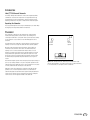
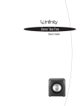
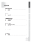
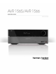
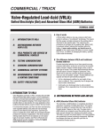
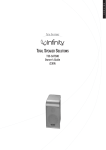
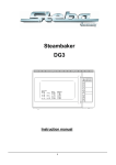
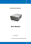
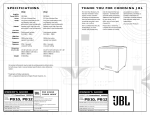
Powered Subwoofer
PS38
(120V)
Owner’s Manual
IMPORTANT SAFETY PRECAUTIONS
Read First!
12. Use only with the cart, stand, tripod, bracket or
table specified by the manufacturer or sold with
the apparatus. When a cart is used,
use caution when moving the cart/
apparatus combination to avoid
injury from tip-over.
13. Unplug this apparatus during lightning storms or
when unused for long periods of time.
14. Refer all servicing to qualified service
personnel. Servicing is required when the
apparatus has been damaged in any way, such
as power-supply cord or plug is damaged, liquid
has been spilled or objects have fallen into the
apparatus, the apparatus has been exposed to
rain or moisture, does not operate normally, or
has been dropped.
1. Read these instructions.
2. Keep these instructions.
3. Heed all warnings.
4. Follow all instructions.
5. Do not use this apparatus near water.
6. Clean only with a dry cloth.
7. Do not block any ventilation openings. Install
in accordance with the manufacturer’s
instructions.
8. Do not install near any heat sources such
as radiators, heat registers, stoves or other
apparatus (including amplifiers) that produce
heat.
9. Do not defeat the safety purpose of the polarized
or grounding-type plug. A polarized plug has
two blades with one wider than the other. A
grounding-type plug has two blades and a third
grounding prong.The wide blade or the third
prong is provided for your safety. If the provided
plug does not fit into your outlet, consult an
electrician for replacement of the obsolete
outlet.
10. Protect the power cord from being walked on
or pinched, particularly at plugs, convenience
receptacles and the point where they exit from
the apparatus.
11. Only use attachments/accessories specified by
the manufacturer.
2
PS38 (120V)
18. An outside antenna system should not be located
in the vicinity of overhead power lines or other
electric light or power circuits, or where it can
fall into such power lines or circuits. When
installing an outside antenna system, extreme
care should be taken to keep from touching such
power lines or circuits, as contact with them
might be fatal.
19. Do not overload wall outlets, extension cords, or
integral convenience receptacles, as this can
result in a risk of fire or electric shock.
20. Never push objects of any kind into this product
through openings, as they may touch dangerous
oltage points or short-out parts that could result
in a fire or electric shock. Never spill liquid of
any kind on the product.
15. Do not use attachments not recommended by
the product manufacturer, as they may cause
hazards.
21. The apparatus shall not be exposed to dripping
or splashing, and no objects filled with liquids,
such as vases, shall be placed on the apparatus.
16. This product should be operated only from the
type of power source indicated on the marking
label. If you are not sure of the type of power
supply to your home, consult your product dealer
or local power company. For products intended
to operate from battery power, or other sources,
refer to the operating instructions.
22. Do not attempt to service this product yourself,
as opening or removing covers may expose you
to dangerous voltage or other hazards. Refer all
servicing to qualified service personnel.
17. If an outside antenna or cable system is
connected to the product, be sure the antenna or
cable system is grounded so as to provide some
protection against voltage surges and built-up
static charges. Article 810 of the National
Electrical Code, ANSI/NFPA 70, provides
information with regard to proper grounding of
the mast and supporting structure, grounding
of the lead-in wire to an antenna discharge
unit, size of grounding conductors, location of
antenna-discharge unit, connection to grounding
electrodes, and requirements for the grounding
electrode. See Figure A.
Figure A.
Example of Antenna Grounding as per
National Electrical Code ANSI/NFPA 70
23. When replacement parts are required, be sure
the service technician has used replacement
parts specified by the manufacturer or that have
the same characteristics as the original part.
Unauthorized substitutions may result in fire,
electric shock or other hazards.
24. Upon completion of any service or repairs to this
product, ask the service technician to perform
safety checks to determine that the product is in
proper operating condition.
25. The product should be mounted to a wall or ceiling
only as recommended by the manufacturer.
INTRODUCTION
Infinity® PS38 Powered Subwoofer
The Infinity® PS38 powered subwoofer continues the longstanding Infinity
commitment to accurate sound reproduction. Our proprietary technology
and engineering resources work together to deliver uncompromised lowfrequency performance in any stereo or multichannel home theater system.
Unpacking the Subwoofer
If you suspect damage from transit, report it immediately to your dealer. Keep
the shipping carton and packing materials for future use.
PLACEMENT
Since installing a subwoofer can be somewhat more complicated than
installing full-range speakers, read this section very carefully prior to
connecting the subwoofer to your system. Should you have questions relating
to your installation, call your dealer or visit www.infinitysystems.com for
assistance.
The performance of the subwoofer is directly related to its placement in the
listening room and how you align the subwoofer with its satellite speakers.
Most audio authorities believe that low frequencies (below 125Hz) are
nondirectional, and, therefore, the location of a subwoofer within any
listening room is not critical; but within the limited confines of a room,
reflections, standing waves and absorptions generated within the room will
strongly influence the performance of any subwoofer system. As a result,
the specific location of the subwoofer becomes important, and we strongly
recommend that you experiment with placement before choosing a final
location.
Placement will depend upon the amount and quality of bass required and upon
your room (for example, whether or not your room permits placement of the
subwoofer near either satellite). Be sure to leave a minimum of 15cm (nearly
six inches) between the wall and the port on the subwoofer.
Subwoofer
Rightchannel
speaker
Leftchannel
speaker
Primary listening area
Figure 1. This example shows the subwoofer positioned behind the rightchannel satellite speaker to re-create the actual location of bass instruments
in an orchestra and/or to add impact to movie soundtracks.
Setting the volume of the subwoofer in relationship to the left and right
speakers is also of critical importance because it is essential that the
subwoofer integrate smoothly with the entire system. Setting the subwoofer’s
volume level too high will result in overpowering, boomy bass. Setting the
volume level too low will negate the benefits of the subwoofer.
PS38 (120V)
3
CONTROLS AND CONNECTIONS
Rear Panel
¡ Subwoofer Level Control
™ Crossover Adjustment Control
¡
£ Phase Switch
¢ LFE Input
™
∞ Line-Level Inputs
§ Power Switch
£
¢
∞
§
FUSE
T 2.5A L 250V
TYPE
4
PS38 (120V)
AC~
120V
60HZ
200 Watts
SYSTEM CONNECTIONS
Choose the Subwoofer Connection that is Most Suitable
for Your Receiver/Processor
If you have a Dolby® Digital or DTS® receiver/processor with a lowfrequency effects (LFE) or subwoofer output:
SUBWOOFER OR
LFE OUTPUT
If your receiver/processor does not contain a Dolby Digital or DTS processor
but has subwoofer outputs:
Receiver/Processor
SUB OUT
L
R
NOTE: Some receivers have one subwoofer output. In that case, we
recommend that you use a Y connector (not included) to maximize
performance.
PS38 (120V)
5
OPERATION
Crossover Adjustment
Power On
The Crossover Adjustment Control ™ determines the highest frequency
at which the subwoofer reproduces sounds. If your main speakers can
comfortably reproduce some low-frequency sounds, set this control to a lower
frequency setting, between 50Hz and 100Hz. This setting will concentrate the
subwoofer’s efforts on the ultradeep bass sounds required by today’s films
and music. If you are using smaller bookshelf speakers that do not extend to
the lower bass frequencies, set the Crossover Adjustment Control to a higher
setting, between 120Hz and 150Hz.
Plug your subwoofer’s AC cord into a wall outlet. Do not use the outlets on the
back of the receiver.
Initially set the Subwoofer Level Control ¡ to the “Min” position.
Turn on your subwoofer by pressing the Power Switch §. Turn on your entire
audio system and start playing a CD or movie soundtrack at a moderate level.
Auto On/Standby
With the Power Switch § in the ON position, the Status LED Light will remain
lit in red or green to indicate the On/Standby mode of the subwoofer.
RED = STANDBY (No signal detected, amp off)
GREEN = ON (Signal detected, amp on)
The subwoofer will automatically enter the Standby mode if it detects no
signal from your system for about 10 minutes. When it detects a signal, the
subwoofer will power on instantly. During periods of normal use, you can
leave the Power Switch § on. You may turn off the Power Switch § for
extended periods of nonoperation, e.g., when you are away on vacation.
Adjust Gain
Turn your Subwoofer Level Control ¡ up to the halfway position. If no sound
emanates from the subwoofer, check the AC-power cord and input cables.
Are the connectors on the cables making proper contact? Is the AC plug
connected to a “live”receptacle? Has the Power Switch § been pressed
to the “On”position? Once you have confirmed that the subwoofer is active,
proceed by playing a CD, record or cassette. Use a selection that has ample
bass.
Set the overall volume control of the preamplifier or stereo to a comfortable
level. Adjust the Subwoofer Level Control ¡ until you obtain a pleasing blend
of bass. Bass response should not overpower the room but rather be adjusted
so there is a harmonious blend across the entire musical range. Many users
have a tendency to set the subwoofer volume too loud, adhering to the belief
that a subwoofer is there to produce lots of bass. This belief is not entirely
true. A subwoofer is there to enhance bass, extending the response of the
entire system so listeners can feel the bass as well as hear it. However, the
system must maintain an overall balance, or the music will not sound natural.
An experienced listener will set the volume of the subwoofer so its impact on
bass response is always there but is never obtrusive.
Phase Control
The Phase Switch £ determines whether the subwoofer speaker’s piston-like
action moves in and out with the main speakers (0°) or opposite the main
speakers (180°). Proper phase adjustment depends on variables such as
room size, subwoofer placement and listener position. Adjust the phase switch
to maximize bass output at the listening position.
6
PS38 (120V)
NOTE: This control will have no effect if the LFE/Normal Selector ¢ is set
to LFE. If you have a Dolby Digital or DTS processor/receiver, it will set the
low-pass frequency. Consult your owner’s manual to learn how to view or
change this setting.
MAINTENANCE AND SERVICE
You may clean the enclosure using a soft cloth to remove fingerprints or to
wipe off dust.
The grille may be gently vacuumed. You may remove stains with an aerosol
cleaner; follow its instructions. Do not use any solvents on the grille.
All wiring connections should be inspected and cleaned or remade
periodically. The frequency of maintenance depends on atmospheric
conditions, the metals involved in the connections and other factors, but once
per year is the minimum.
If your subwoofer ever needs service, contact your local Infinity dealer or
distributor, or visit www.infinitysystems.com to find a service center near you.
SPECIFICATIONS
PS38
Frequency response:
35Hz – 150Hz (±3dB)
Maximum amplifier output:
150 watts RMS
300 watts peak
Crossover frequency:
50Hz – 150Hz,
24dB/octave, continuously variable
Driver:
8" (200mm) MMD® transducer
Dimensions (H x W x D):
(with grille)
17-7/8" x 10-5/8" x 16-1/2"
(454mm x 270mm x 419mm)
Weight:
31.7 lb (14.4kg)
(20Hz – 150Hz with
no more than 0.1% THD)
Infinity engineers continually strive to update and improve existing products as well
as to create new ones. The specifications and construction details in this and related
Infinity publications are therefore subject to change without notice.
PS38 (120V)
7
Harman Consumer, Inc.
8500 Balboa Blvd., Northridge, CA 91329 USA
© 2010 Harman International Industries, Incorporated. All rights reserved.
Infinity and MMD are trademarks of Harman International Industries, Incorporated,
registered in the United States and/or other countries. Dolby is a registered
trademark of Dolby Laboratories. DTS is a registered trademark of DTS, Inc.
Features, specifications and appearance are subject to change without notice.
Part No. 950-0304-001 6/10
www.infinitysystems.com