1
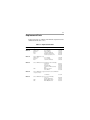
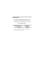
USER’S MANUAL
MM23002D Series
SCR, Dual Voltage,
Adjustable Speed Drives
for PM DC Brush Motors
Copyright © 2006 by
Minarik Drives
All rights reserved. No part of this manual may be reproduced or transmitted in any
form without written permission from Minarik Drives. The information and technical
data in this manual are subject to change without notice. Minarik Drives and its
Divisions make no warranty of any kind with respect to this material, including, but
not limited to, the implied warranties of its merchantability and fitness for a given
purpose. Minarik Drives and its Divisions assume no responsibility for any errors that
may appear in this manual and make no commitment to update or to keep current
the information in this manual.
Printed in the United States of America.
i
Safety Warnings
• This symbol denotes an important safety tip or warning.
Please read these instructions carefully before performing
any of the procedures contained in this manual.
•
DO NOT INSTALL, REMOVE, OR REWIRE THIS
EQUIPMENT WITH POWER APPLIED. Have a qualified
electrical technician install, adjust and service this equipment.
Follow the National Electrical Code and all other applicable
electrical and safety codes, including the provisions of the
Occupational Safety and Health Act (OSHA), when installing
equipment.
•
Reduce the chance of an electrical fire, shock, or explosion by
proper grounding, over-current protection, thermal protection,
and enclosure. Follow sound maintenance procedures.
It is possible for a drive to run at full speed as a result of
a component failure. Minarik strongly recommends the
installation of a master switch in the main power input to
stop the drive in an emergency.
Circuit potentials are at 115 VAC or 230 VAC above
earth ground. Avoid direct contact with the printed circuit
board or with circuit elements to prevent the risk of serious
injury or fatality. Use a non-metallic screwdriver for
adjusting the calibration trimpots. Use approved personal
protective equipment and insulated tools if working on this
drive with power applied.
ii
Contents
Safety Warnings
i
Specifications
1
Model Number Suffix Definitions
2
Dimensions
3
Installation
7
Chassis drives . . . . . . . . . . . . . . . . . . . . . . . . . . . . . . . . . . . . . . . . . . . . . . . . . .7
Mounting . . . . . . . . . . . . . . . . . . . . . . . . . . . . . . . . . . . . . . . . . . . . . . . . . . . . .7
Wiring . . . . . . . . . . . . . . . . . . . . . . . . . . . . . . . . . . . . . . . . . . . . . . . . . . . . . . .8
Shielding guidelines . . . . . . . . . . . . . . . . . . . . . . . . . . . . . . . . . . . . . . . . . . . .9
Speed adjust potentiometer . . . . . . . . . . . . . . . . . . . . . . . . . . . . . . . . . . . . .10
Line fusing . . . . . . . . . . . . . . . . . . . . . . . . . . . . . . . . . . . . . . . . . . . . . . . . . .11
Heat sinking . . . . . . . . . . . . . . . . . . . . . . . . . . . . . . . . . . . . . . . . . . . . . . . . .12
Connections . . . . . . . . . . . . . . . . . . . . . . . . . . . . . . . . . . . . . . . . . . . . . . . . .12
Power, fuse and motor connections . . . . . . . . . . . . . . . . . . . . . . . . . . . .13
Motor . . . . . . . . . . . . . . . . . . . . . . . . . . . . . . . . . . . . . . . . . . . . . . . . . . . .13
Power input . . . . . . . . . . . . . . . . . . . . . . . . . . . . . . . . . . . . . . . . . . . . . . .13
Line fuse . . . . . . . . . . . . . . . . . . . . . . . . . . . . . . . . . . . . . . . . . . . . . . . . .13
Master power switch . . . . . . . . . . . . . . . . . . . . . . . . . . . . . . . . . . . . . . . . . .14
Alternate speed adjust potentiometer connections . . . . . . . . . . . . . . . . . . .14
Voltage follower . . . . . . . . . . . . . . . . . . . . . . . . . . . . . . . . . . . . . . . . . . . . . .16
Cased drives . . . . . . . . . . . . . . . . . . . . . . . . . . . . . . . . . . . . . . . . . . . . . . . . . .17
Mounting (NEMA 1 enclosures) . . . . . . . . . . . . . . . . . . . . . . . . . . . . . . . . . .17
Mounting (NEMA 12/4/4X enclosures) . . . . . . . . . . . . . . . . . . . . . . . . . . . . .18
Heat sinking . . . . . . . . . . . . . . . . . . . . . . . . . . . . . . . . . . . . . . . . . . . . . . . . .19
Line fusing . . . . . . . . . . . . . . . . . . . . . . . . . . . . . . . . . . . . . . . . . . . . . . . . . .19
All drives . . . . . . . . . . . . . . . . . . . . . . . . . . . . . . . . . . . . . . . . . . . . . . . . . . . . . .20
Operation
22
Switch settings . . . . . . . . . . . . . . . . . . . . . . . . . . . . . . . . . . . . . . . . . . . . . . . . .23
Before applying power . . . . . . . . . . . . . . . . . . . . . . . . . . . . . . . . . . . . . . . . . . . .24
Speed Mode . . . . . . . . . . . . . . . . . . . . . . . . . . . . . . . . . . . . . . . . . . . . . . . . .25
Torque Mode . . . . . . . . . . . . . . . . . . . . . . . . . . . . . . . . . . . . . . . . . . . . . . . . .25
Speed Mode Startup . . . . . . . . . . . . . . . . . . . . . . . . . . . . . . . . . . . . . . . . . . . . .27
MM23002 and MM23012 . . . . . . . . . . . . . . . . . . . . . . . . . . . . . . . . . . . . . .27
MM23102, MM23112, MM23402 and MM23412 . . . . . . . . . . . . . . . . . . . . .27
MM23202 and MM23212 . . . . . . . . . . . . . . . . . . . . . . . . . . . . . . . . . . . . . . .28
iii
Starting and Stopping Methods . . . . . . . . . . . . . . . . . . . . . . . . . . . . . . . . . . . . .29
Line starting and line stopping . . . . . . . . . . . . . . . . . . . . . . . . . . . . . . . . . . .29
Inhibit terminals . . . . . . . . . . . . . . . . . . . . . . . . . . . . . . . . . . . . . . . . . . . . . .30
Decelerating to minimum speed . . . . . . . . . . . . . . . . . . . . . . . . . . . . . . . . .32
Dynamic braking . . . . . . . . . . . . . . . . . . . . . . . . . . . . . . . . . . . . . . . . . . . . . .33
Dynamic brake resistor value . . . . . . . . . . . . . . . . . . . . . . . . . . . . . . . . .33
Calibration
35
MIN SPD . . . . . . . . . . . . . . . . . . . . . . . . . . . . . . . . . . . . . . . . . . . . . . . . . . . . .37
MAX SPD . . . . . . . . . . . . . . . . . . . . . . . . . . . . . . . . . . . . . . . . . . . . . . . . . . . . .37
TORQUE . . . . . . . . . . . . . . . . . . . . . . . . . . . . . . . . . . . . . . . . . . . . . . . . . . . . . .38
IR COMP . . . . . . . . . . . . . . . . . . . . . . . . . . . . . . . . . . . . . . . . . . . . . . . . . . . . . .39
ACCEL . . . . . . . . . . . . . . . . . . . . . . . . . . . . . . . . . . . . . . . . . . . . . . . . . . . . . . .40
DECEL . . . . . . . . . . . . . . . . . . . . . . . . . . . . . . . . . . . . . . . . . . . . . . . . . . . . . . .41
Torque Mode Calibration . . . . . . . . . . . . . . . . . . . . . . . . . . . . . . . . . . . . . . . . . .42
Application Notes
44
Multiple fixed speeds . . . . . . . . . . . . . . . . . . . . . . . . . . . . . . . . . . . . . . . . . . . .44
Adjustable speeds using potentiometers in series . . . . . . . . . . . . . . . . . . . . . .45
Independent adjustable speeds . . . . . . . . . . . . . . . . . . . . . . . . . . . . . . . . . . . .46
RUN / JOG switch . . . . . . . . . . . . . . . . . . . . . . . . . . . . . . . . . . . . . . . . . . . . . .47
Leader-follower application . . . . . . . . . . . . . . . . . . . . . . . . . . . . . . . . . . . . . . . .49
Single speed potentiometer control of multiple drives . . . . . . . . . . . . . . . . . . .50
Reversing . . . . . . . . . . . . . . . . . . . . . . . . . . . . . . . . . . . . . . . . . . . . . . . . . . . . .51
Reversing with a DIGI-LOK® controller . . . . . . . . . . . . . . . . . . . . . . . . . . . . . . .52
Troubleshooting
53
Before troubleshooting . . . . . . . . . . . . . . . . . . . . . . . . . . . . . . . . . . . . . . . . . . .53
Diagnostic LEDs . . . . . . . . . . . . . . . . . . . . . . . . . . . . . . . . . . . . . . . . . . . . . . . .54
Power (PWR): . . . . . . . . . . . . . . . . . . . . . . . . . . . . . . . . . . . . . . . . . . . .54
Current Limit (CURR LIMIT or CL): . . . . . . . . . . . . . . . . . . . . . . . . . . . .54
Functional Diagrams . . . . . . . . . . . . . . . . . . . . . . . . . . . . . . . . . . . . . . . . . . . . .58
Replacement Parts . . . . . . . . . . . . . . . . . . . . . . . . . . . . . . . . . . . . . . . . . . . . . .61
Certificate of Compliance
63
Line Filters . . . . . . . . . . . . . . . . . . . . . . . . . . . . . . . . . . . . . . . . . . . . . . . . . . . .64
Armature Filters . . . . . . . . . . . . . . . . . . . . . . . . . . . . . . . . . . . . . . . . . . . . . . . . .65
Unconditional Warranty
inside back cover
iv
Illustrations
Figure
Figure
Figure
Figure
Figure
Figure
Figure
Figure
Figure
Figure
Figure
Figure
Figure
Figure
Figure
Figure
Figure
Figure
Figure
Figure
Figure
Figure
Figure
Figure
Figure
Figure
Figure
Figure
Figure
1. MM23002D and MM23012D Dimensions . . . . . . . . . . . . . . . . . . . . . . . .3
2. MM23102D, MM23112D, MM23202D, and MM23212D Dimensions . . .4
3. MM23402D and MM23412D Dimensions . . . . . . . . . . . . . . . . . . . . . . . .5
4. Heat Sink Dimensions . . . . . . . . . . . . . . . . . . . . . . . . . . . . . . . . . . . . . . .6
5. Speed Adjust Potentiometer . . . . . . . . . . . . . . . . . . . . . . . . . . . . . . . . . .10
6. Chassis Drive Connections . . . . . . . . . . . . . . . . . . . . . . . . . . . . . . . . . .15
7. Voltage Follower Connections . . . . . . . . . . . . . . . . . . . . . . . . . . . . . . . .16
8. Cased Drive Connections . . . . . . . . . . . . . . . . . . . . . . . . . . . . . . . . . . .21
9. Voltage Switches . . . . . . . . . . . . . . . . . . . . . . . . . . . . . . . . . . . . . . . . . .23
10. J503 SPEED/TORQUE Jumper Settings . . . . . . . . . . . . . . . . . . . . . . .26
11. J503 SPEED/TORQUE Jumper Location . . . . . . . . . . . . . . . . . . . . . .26
12. INHIBIT Terminals . . . . . . . . . . . . . . . . . . . . . . . . . . . . . . . . . . . . . . . .30
13. Inhibit Personality Configuration . . . . . . . . . . . . . . . . . . . . . . . . . . . . .31
14. Run/Decelerate to Minimum Speed Switch . . . . . . . . . . . . . . . . . . . . .32
15. Dynamic Brake Connection . . . . . . . . . . . . . . . . . . . . . . . . . . . . . . . . .34
16. Calibration Trimpot Layout . . . . . . . . . . . . . . . . . . . . . . . . . . . . . . . . . .36
17. Recommended Torque and IR COMP Settings . . . . . . . . . . . . . . . . .42
18. Multiple Fixed Speeds . . . . . . . . . . . . . . . . . . . . . . . . . . . . . . . . . . . . .43
19. Adjustable Fixed Speeds Using Potentiometers in Series . . . . . . . . . .44
20. Independent Adjustable Speeds . . . . . . . . . . . . . . . . . . . . . . . . . . . . .45
21. RUN / JOG Switch Connection to Inhibit Plug . . . . . . . . . . . . . . . . . . .46
22. RUN / JOG Switch Connection to Speed Adjust Potentiometer . . . . .47
23. Leader-Follower Application . . . . . . . . . . . . . . . . . . . . . . . . . . . . . . . . .48
24. Single Speed Potentiometer Control of Multiple Drives . . . . . . . . . . . .49
25. Reversing Circuit Connection . . . . . . . . . . . . . . . . . . . . . . . . . . . . . . .50
26. Reversing with a DLC600 . . . . . . . . . . . . . . . . . . . . . . . . . . . . . . . . . .52
27. Diagnostic LED Locations . . . . . . . . . . . . . . . . . . . . . . . . . . . . . . . . . .54
28. MM23000 Series Block Diagram . . . . . . . . . . . . . . . . . . . . . . . . . . . . .58
29. MM23102, MM23112, MM23402 and MM23412
Terminal Block Connections . . . . . . . . . . . . . . . . . . . . . . . . . . . . . . . . .59
Figure 30. MM23202 and MM23212 Terminal Block Connections . . . . . . . . . . . .60
Tables
Table
Table
Table
Table
1.
2.
3.
4.
Recommended Line Fuse Sizes . . . . . . . . . . . . . . . . . . . . . . . . . . . . . . .11
Replacement Parts . . . . . . . . . . . . . . . . . . . . . . . . . . . . . . . . . . . . . . . . .61
Corcom® Filters . . . . . . . . . . . . . . . . . . . . . . . . . . . . . . . . . . . . . . . . . . .64
Minarik® Filters . . . . . . . . . . . . . . . . . . . . . . . . . . . . . . . . . . . . . . . . . . . .65
1
Specifications
Model
MM23012D
MM23112D
MM23212D
MM23412D
MM23002D †
MM23102D ‡
MM23202D ‡
MM23402D
Max.
Armature
Current
(Amps DC)
1.5
HP Range
with 115 VAC
Applied
1/20–1/8
HP Range
with 230 VAC
Applied
1/10–1/4
5.0
1/8–1/2
1/4–1
10.0
1/8–1
1/4–2
Style
Chassis
NEMA 1
NEMA 1
NEMA 12/4/4X
Chassis
NEMA 1
NEMA 1
NEMA12/4/4X
† Double maximum armature current and horsepower when drive is mounted on heat
sink part number 223-0159.
‡ Double maximum armature current and horsepower when drive is mounted on heat
sink part number 223-0174.
AC Line Voltage
115 VAC or 230 VAC ±10%, 50/60 Hz, single phase
Armature Voltage (115 VAC Input)
0–90 VDC
Armature Voltage (230 VAC Input)
0–180 VDC
Form Factor
1.37 at base speed
Accel. Time Range
(for 0–90 VDC Armature Voltage)
0.5–17 seconds
(for 0–180 VDC Armature Voltage)
0.5–17 seconds
Decel. Time Range
(for 0-90 VDC Armature Voltage)
coast to a stop–25 seconds
(for 0–180 VDC Armature Voltage)
coast to a stop–25 seconds
Analog Input Voltage Range (input must be isolated; S1 to S2)
0–2.5 VDC
Input Impedance (S1 to S2)
100K ohms
Speed adjust potentiometer rating
10k ohm, 5W (5k ohms acceptable)
Load Regulation
1% base speed or better
2
Vibration
Safety Certification
Ambient Temp. Range (chassis drive)
Ambient Temp. Range (cased drive)
0.5G max (0–50 Hz)
0.1G max (>50 Hz)
UL Recognized Component, file # E132235
CSA Certified Component, file # LR41380
CE Certificate of Compliance
10°C–55°C
10°C–40°C
Model Number Suffix Definitions
A:
C:
C-H:
D:
Basic drive
Basic drive with current limit LED
Basic drive with power supply header block.
Basic drive with power supply header block, power and
current limit LEDs, and torque mode.
3
Dimensions
SCR501
D 502
S C R5 0 2
C503
R501
0.19 [5]
R502
C505
MOV502
D503
D501
MOV501
L1
L2
C50 1
T501
115
SW501
IC502
IC501
230
3.58 [91]
A2
C 502
SO501
SO502
+ INH J 5 02
SW503
OUTPUT
1
1
3
A1
C504
SW502
1.75 [44]
4
J 50 1
S3
S2
S1
J503
1
5
C 506
POWER
TQ LIMIT
0.74 [19]
0.64 [16]
3.80 [97]
4.30 [109]
0.19 [5]
1.60 [41]
1.28 [33]
0.96 [24]
3.80 [97]
4.30 [109]
ALL DIMENSIONS IN INCHES [MILLIMETERS]
Figure 1. MM23002D and MM23012D Dimensions
4
6.00 [152]
1.79 [45]
2.50 [64]
8.00 [203]
2.50 [64]
5.00 [127]
THREE KEYHOLES FOR #10
SCREW ON BACK SIDE
FOR MOUNTING
3.46 [88]
2.75 [70]
1.72 [44]
2.50 [64]
TWO 0.88 [22] CONDUIT HOLES
ON BOTTOM SIDE
ALL DIMENSIONS IN INCHES [MILLIMETERS]
Figure 2. MM23102D, MM23112D, MM23202D,
and MM23212D Dimensions
5
6.90 [175]
6.30 [160]
0.87 [22]
7.76 [197]
8.20 [208]
6.00 [152]
FOUR MOUNTING SLOTS 0.19 INCHES [5 MILLIMETERS] WIDE
4.50 [114]
3.70 [94]
2.25 [57]
0.13 [3]
2.50 [64]
TWO 0.88 [22] CONDUIT KNOCKOUTS ON BOTTOM SIDE
ALL DIMENSIONS IN INCHES [MILLIMETERS]
Figure 3. MM23402 and MM23412 Dimensions
6
6.90
6.90 [175]
[175]
6.30 [160]
6.30
[160]
5.90 [150]
5.90
[150]
C
A
A
BB
MOUNTING
SLOTS
0.19X X0.34
0.34[5
[5 X
X 9]
MOUNTING SLOTS
0.19
9]
ALL DIMENSIONS IN INCHES [MILLIMETERS]
ALL DIMENSIONS IN INCHES [MILLIMETERS]
1.00
[25]
1.00
[25]
0.13 [3]
0.13
[3]
PART NO.
DIM “A”
DIM “B”
DIM “C”
223-0159
4.40 [112]
223-0174
7.78 [198]
Heat sinks sold separately.
3.00 [76]
6.00 [152]
0.7 [18]
0.89 [23]
Figure 4. Heat Sink Dimensions
7
Installation
Chassis drives
Mounting
Warning
Do not install, rewire, or remove this control with power
applied. Doing so may cause fire or serious injury. Make
sure you have read and understood the Safety Warnings
before attempting installation.
The chassis must be earth grounded. Use a star washer
beneath the head of at least one of the mounting screws to
penetrate the anodized chassis surface and to reach bare
metal.
• Drive components are sensitive to electrostatic fields. Avoid
contact with the circuit board directly. Hold the drive by the
chassis only.
• Mount the drive with its board in either a horizontal or vertical
plane. Six 0.19 inch (5 mm) wide slots in the chassis accept #8
pan head screws. Fasten either the large base or the narrow
flange of the chassis to the subplate.
8
Wiring
Warning
Do not install, remove, or rewire this equipment with
power applied. Failure to heed this warning may result in
fire, explosion, or serious injury.
Circuit potentials are at 115 or 230 VAC above ground. To
prevent the risk of injury or fatality, avoid direct contact with
the printed circuit board or with circuit elements.
Do not disconnect any of the motor leads from the drive
unless power is removed or the drive is disabled. Opening
any one motor lead may destroy the drive.
• Use 18-24 AWG wire for speed adjust potentiometer wiring.
Use 14–16 AWG wire for AC line (L1, L2) and motor (A1 and
A2) wiring.
9
Shielding guidelines
Warning
Under no circumstances should power and logic leads be
bundled together. Induced voltage can cause unpredictable
behavior in any electronic device, including motor controls.
As a general rule, Minarik recommends shielding of all
conductors.
If it is not practical to shield power conductors, Minarik
recommends shielding all logic-level leads. If shielding is not
practical, the user should twist all logic leads with themselves to
minimize induced noise.
It may be necessary to earth ground the shielded cable. If noise is
produced by devices other than the drive, ground the shield at the
drive end. If noise is generated by a device on the drive, ground
the shield at the end away from the drive. Do not ground both
ends of the shield.
If the drive continues to pick up noise after grounding the shield,
it may be necessary to add AC line filtering devices, or to mount
the drive in a less noisy environment.
10
Speed adjust potentiometer
Warning
Be sure that the potentiometer tabs do not make contact with
the potentiometer enclosure. Grounding the input will cause
damage to the drive.
On chassis drives, install the circular insulating disk between
the panel and the 10K ohm speed adjust potentiometer. Mount the
speed adjust potentiometer through a 0.38 inch (10 mm) hole with
the hardware provided (Figure 5). Twist the speed adjust
potentiometer wire to avoid picking up unwanted electrical noise.
If potentiometer leads are longer than 18 inch (457 mm), use
shielded cable.
All cased controls come with the speed adjust potentiometer
installed.
MOUNT
0.38
IN (10
MOUNTTHROUGH
THROUGHA A
0.38
IN.MM)
(10HOLE
MM) HOLE
CW
CW
WIPER
WIPER
CCW
CCW
NUT
NUT
STAR
STAR
WASHER
SPEED
SPEED ADJUST
POTENTIOMETER
POTENTIOMETER
WASHER
INSULATING DISK
DISK
INSULATING
POTTAB
TAB ASSIGNMENTS
POT
ASSIGNMENTS
PANEL
PANEL
Figure 5. Speed Adjust Potentiometer
11
Line fusing
Minarik drives require an external fuse for protection. Use fast
acting fuses rated for 250 VAC or higher, and approximately
150% of the maximum armature current. Fuse only the hot leg
of the AC line that connects to L1 and leave L2 unfused when the
AC line voltage is 115 VAC. Fuse both L1 and L2 when the AC
line voltage is 230 VAC. Fuse blocks are included on cased
drives only. Table 1 lists the recommended line fuse sizes.
Table 1. Recommended Line Fuse Sizes
90 VDC Motor
180 VDC Max. DC Armature
Horsepower Horsepower Current (amps)
1/20
1/10
0.5
1/15
1/8
0.8
1/8
1/4
1.5
1/6
1/3
1.7
1/4
1/2
2.6
1/3
3/4
3.5
1/2
1
5.0
3/4
1 1/2
7.6
1
2
10
AC Line Fuse
Size (amps)
1
1.5
3
3
5
8
10
15
15
12
Heat sinking
Model MM23002D requires an additional heat sink, Minarik part
number 223-0159, when the continuous armature current is above
5 ADC. All other chassis drives have sufficient heat sinking in
their basic configurations. Use a thermally conductive heat sink
compound (such as Dow Corning® 340 Heat Sink Compound)
between the drive chassis and heat sink surface for optimum heat
transfer.
Connections
Warning
Do not connect this equipment with power applied.
Failure to heed this directive may result in fire or serious
injury.
For chassis drives, Minarik strongly recommends the
installation of a master power switch in the voltage input line
as shown in Figure 6 (page 15). The switch contacts should
be rated at a minimum of 200% of motor nameplate current
and 250 volts.
13
Power, fuse and motor connections
Connect the power input leads, an external line fuse and a DC
motor to the drive’s printed circuit board (PCB) as shown in
Figure 6, page 15.
Motor
Connect a motor to PCB terminals A1 and A2. Ensure that the
motor voltage rating is consistent with the drive’s output
voltage.
Power input
Connect the AC line power leads to terminals L1 and L2, or to a
double-pole, single-throw master power switch as shown in
Figure 6, page 15 (recommended).
Line fuse
Wire an external line fuse between the stop switch (if installed)
and the L1 terminal on the PCB. An additional line fuse should
be installed on L2 if the input voltage is 230VAC. The line
fuse(s) should be rated at 250 volts and 150 - 200% of maximum
motor nameplate current. Refer to the Table 1 on page 11 for fuse
ratings.
14
Master power switch
If you use a chassis (uncased) drive, Minarik strongly
recommends the installation of a master power switch in the
voltage input line, as shown in Figure 6. The switch
contacts should be rated at a minimum of 200% of motor
nameplate current and 250 volts.
Alternate speed adjust potentiometer connections
Refer to Application Notes section (page 44) for additional speed
adjust potentiometer connections.
15
SCR501
D 5 02
SC R5 02
C503
R501
R502
C505
MOV502
D503
D 50 1
MOV501
L1
L2
C50 1
T501
115
SW501
IC502
IC501
230
FUSE
A2
C502
SO501
SO502
+ INH 3
A1
SW503
OUTPUT
1
1
J 5 02
SW502
NOTE: DO NOT ADD
FUSE TO L2 UNLESS
INPUT VOLTAGE IS 230 VAC
C5 0 4
4
J 50 1
S3
S2
S1
J 50 3
1
5
C5 0 6
POWER
TQ LIMIT
EMERGENCY
STOP SWITCH
MOTOR
10K OHM
SPEED ADJUST
POTENTIOMETER
Figure 6. Chassis Drive Connections
16
Voltage follower
Instead of using an external speed or torque adjust potentiometer,
the drive may be wired to follow an analog input voltage signal
that is isolated (Figure 7). The analog input voltage range is 0 2.5 VDC.
Connect the signal input (+) to S2. Connect the signal
common (-) to S1. Make no connection to S3. A potentiometer
can be used to scale the analog input voltage. An interface device
such as Minarik model PCM4, may be used to scale and isolate an
analog input voltage.
Isolated Signal Input
Isolated Signal Common
+
–
S2
S1
MM23000
Series
Drive
0 - 2.5 VDC
Figure 7. Voltage Follower Connections
17
Cased drives
Mounting (NEMA 1 enclosures)
NEMA 1 cased drives come with 0.88 inch (22 mm) conduit
holes at the bottom of the case. The units may be vertically wall
mounted or horizontally bench mounted using the three keyholes
on the back of the case (see Figure 2, page 4).
1. For access to the keyholes and the terminal strip, remove the
two screws from the front of the case by turning them
counterclockwise. Grasp the front cover and lift it straight out.
2. Install the mounting screws in the three keyholes.
3. Install conduit hardware through the conduit holes at the
bottom of the case. Connect external wiring to the terminal
block. Refer to Figure 8 on page 21.
4. Reinstall the front cover. Avoid pinching any wires between the
front cover and the case.
5. Replace the two screws to the front cover. Turn the screws
clockwise to tighten.
6. Set the POWER switch to the OFF position before applying the
AC line voltage.
18
Mounting (NEMA 12 / 4 / 4X enclosures)
NEMA 12 / 4 / 4X cased drives come with two 0.88 inch (22
mm) conduit knockout holes at the bottom of the case. The units
may be vertically wall mounted using the four 0.19 inch (5 mm)
slotted holes on the attached heat sink (see Figure 3, page 5). For
motor loads less than 5 ADC, the drive may be bench mounted
horizontally, or operated without mounting.
1. Install the mounting screws.
2. For access to the terminal strip, turn the slotted screw on the
front cover counterclockwise until it is free from the case. The
right side of the cover is hinged to the case. Pull the slotted
screw to open the case.
3. Carefully remove the conduit knockouts by tapping them into
the case and twisting them off with pliers.
4. Install conduit hardware through the 0.88 inch (22 mm)
conduit holes. Connect external wiring to the terminal block.
5. Grasp the slotted screw and tilt the front cover back into place.
Avoid pinching any wires between the front cover and the case.
6. Turn the slotted screw clockwise until tight to secure the front
cover.
7. Set the POWER switch to the OFF position before applying the
AC line voltage.
19
Heat sinking
Models MM23102 and MM23202 require additional heat
sinking when the continuous armature current is above 5 ADC.
Use Minarik part number 223-0174. All other cased drives
have sufficient heat sinking in their basic configurations. Use a
thermally conductive heat sink compound (such as Dow
Corning® 340 Heat Sink Compound) between the back of the
drive case and heat sink surface for optimum heat transfer.
Line fusing
15-amp line fuses are preinstalled on models MM23102,
MM23202 and MM23402 and 3-amp line fuses are preinstalled
on models MM23112, MM23212, and MM23412.
If the horsepower rating of the motor being used is less than the
maximum horsepower rating of the drive, the line fuse may have
to be replaced with a lower rated one. Refer to the
“Recommended Line Fuse Sizes”, Table 1 on page 11 to install a
lower rated fuse.
20
All drives
• Protect the drive from dirt, moisture, and accidental contact.
Provide sufficient room for access to the terminal block and
calibration trimpots.
• Mount the drive away from other heat sources. Operate the
drive within the specified ambient operating temperature range.
• Prevent loose connections by avoiding excessive vibration of
the drive.
21
1
2
3
4
5
6
7
NNOT
O T USED
USED
+
115 VAC
MOTOR
ARMATURE
EARTH GROUND
(GREEN SCREW)
230 VAC
LINE VOLTAGE INPUTS
(115 VAC OR 230 VAC)
Figure 8. Cased Drive Connections
22
Operation
Warning
Dangerous voltages exist on the drive when it is powered.
BE ALERT. High voltages can cause serious or fatal injury.
Change voltage switch settings only when the drive is
disconnected from AC line voltage. Make sure both switches
are set to their correct position. If the switches are
improperly set to a lower voltage position, the motor will not
run at full voltage and may cause damage to the transformer.
If the switches are improperly set to a higher voltage
position, the motor will overspeed, which may cause motor
damage.
23
Switch settings
Set voltage switch SW501and SW502 to either 115V or 230V to
match the AC line voltage.
Set voltage switch SW503 to either 90V or 180V to match the
maximum armature voltage. Refer to Figure 9 for switch
locations.
INPUT
VOLTAGE
SELECT
SW501
INPUT
VOLTAGE
SELECT
SW502
115
SW501
IC502
IC501
230 230
AC INPUT
A1
A2
C502
C504
90
OUTPUT
SW502
+15V @ 10mA
115
SW503
180
SO501
1
S3
S2
S1
MOTOR ARMATURE
VOLTAGE
SW503
Figure 9. Voltage Switches
24
Before applying power
Warning
If the motor does not respond as desired to signal input,
remove line power immediately. Refer to the
Troubleshooting section on page 53 for assistance.
• Ensure that all selector switches are set to their proper
positions.
• Verify that no conductive material is present on the printed
circuit board.
• If using a 90 VDC or 130 VDC motor with 230 VAC line
voltage, derate the nameplate motor speed and torque by at
least 30%. Contact the factory for details.
25
Warning
TORQUE and MAX SPD trimpots must be recalibrated
everytime the drive is switched between SPEED and
TORQUE mode.
Speed Mode
In Speed Mode, the external potentiometer adjusts the speed
(voltage) of the motor. The on-board Torque trimpot sets the
maximum torque available. The drive comes factory calibrated for
speed mode.
To run the drive in Speed Mode, jumper pins 2 & 3 and pins 4 &
5 on J503. See Figure 10 and Figure 11 on page 26.
Torque Mode
In Torque Mode, the external potentiometer adjusts the torque
(current) of the motor. The on-board MAX SPD trimpot sets the
maximum torque limit. The on-board TORQUE trimpot sets the
maximum speed to the motor.
To run the drive in Torque Mode, jumper pins 1 & 2 and pins 3 &
4 on J503. See Figure 10 and 11 on page 26.
26
1
J503
Speed Mode
Jumper pins 2 & 3 and pins 4 & 5 on J503
5
1
J503
Torque Mode
Jumper pins 1 & 2 and pins 3 & 4 on J503
5
SW50
SW
Figure 10. J503 SPEED/TORQUE Jumper Settings
J503
Speed/Torque
Jumper
SO501
+ INH -
1
S2
S1
1
C5 06
SO502
1
J502
S3
OUTPUT
3
4
J50 1
5
J 5 03
POWER
TQ LIMIT
Figure 11. J503 SPEED/TORQUE Jumper Location
27
Speed Mode Startup
MM23002 and MM23012
1. Turn the speed adjust potentiometer full counterclockwise
(CCW).
2. Apply AC line voltage.
3. Slowly advance the speed adjust potentiometer clockwise
(CW). The motor slowly accelerates as the potentiometer is
turned CW. Continue until the desired speed is reached.
4. Remove AC line voltage from the drive to coast the motor to a
stop.
MM23102, MM23112, MM23402 and MM23412
1. Set the speed adjust potentiometer to “0” (full CCW).
2. Apply AC line voltage.
3. Set the POWER switch to the ON position.
4. Slowly advance the speed adjust potentiometer clockwise
(CW). The motor slowly accelerates as the potentiometer is
turned CW. Continue until the desired speed is reached.
5. Set the POWER switch to the OFF position to coast the motor
to a stop.
28
MM23202 and MM23212
Warning
Do not change the FORWARD / REVERSE switch while
the motor is running. The motor must come to a complete
stop before reversing. Changing motor direction before
allowing the motor to completely stop will cause excessively
high current to flow in the armature circuit, and will damage
the drive and/or motor.
1. Set the RUN / BRAKE switch to the BRAKE position.
2. Set the speed adjust potentiometer to “0” (full CCW).
3. Apply AC line voltage.
4. Set the POWER switch to the ON position.
5. Set the FORWARD / REVERSE switch to the desired direction
of rotation.
6. Set the RUN/BRAKE switch to the RUN position.
7. Slowly advance the speed adjust potentiometer clockwise
(CW). The motor slowly accelerates as the potentiometer is
turned CW. Continue until the desired speed is reached.
8. To reverse direction:
a. Set the RUN / BRAKE switch to the BRAKE position.
b. Set the FORWARD / REVERSE switch to the desired
direction of rotation.
c. Set the RUN / BRAKE switch to the RUN position.
9. To brake the motor, set the RUN / BRAKE switch to the
BRAKE position. To coast the motor to a stop, set the POWER
switch to the OFF position.
29
Starting and Stopping Methods
Warning
Minarik strongly recommends the installation of an
emergency stop switch. The switch contacts should be rated
at a minimum of 125 volts and 200% of maximum motor
current.
For frequent starts and stops, short the inhibit terminals,
decelerate to a minimum speed, or apply a dynamic brake to
the motor. Do not use any of these methods for emergency
stopping. They may not stop a drive that is malfunctioning.
Removing AC line power (both L1 and L2) is the only
acceptable method for emergency stopping.
Frequent starting and stopping can produce high torque. This
may cause damage to motors, especially gearmotors that are
not properly sized for the application.
Line starting and line stopping
Line starting and line stopping (applying and removing AC line
voltage) is recommended for infrequent starting and stopping of a
drive only. When AC line voltage is applied to the drive, the
motor accelerates to the speed set by the speed adjust
potentiometer. When AC line voltage is removed, the motor
coasts to a stop.
30
Inhibit terminals
Open or short the INHIBIT terminals to coast the motor to
minimum or zero speed (see Figure 12 for INHIBIT terminal
location). Reopen the INHIBIT terminals to accelerate the motor
to set speed. The drive will exhibit different responses to shorting
these terminals, depending on the way they are shorted (see
Figure 13, page 31). The INHIBIT function is the same for Speed
or Torque Mode.
Minarik Corporation offers two accessory plug harnesses for
connecting to the INHIBIT terminals: part number 201-0024
[inhibit plug with 18 inch (46 cm) leads]; and part number
201-0079 [inhibit plug with 36 inch (91 cm) leads].
S
Twist inhibit wires and separate them from other power-carrying
wires or sources of electrical noise. Use shielded cable if the
inhibit wires are longer than 18 inches (46 cm). If shielded cable
is used, ground only one end of the shield to earth ground. Do not
ground both ends of the shield. See Shielding Guidelines, page 9.
SO501
1
+ INH -
INHIBIT
Terminals
S3
S2
S1
1
C5 06
SO502
1
J502
3
4
J50 1
5
J 5 03
POWER
Figure 12. INHIBIT Terminals
TQ LIMIT
31
CONFIGURATION
INHIBIT
TERMINALS
S0502
J501
1 2 3
J502
TERMINALS
SHORTED
INHIBIT
TERMINALS
S0502
1
2
3
4
J502
INHIBIT ZERO MODE
INHIBITS TO ZERO SPEED
WHEN INHIBIT TERMINALS
ARE SHORTED
1
2
3
4
TERMINALS
SHORTED
INHIBIT
TERMINALS
S0502
J501
1 2 3
1
2
3
4
J502
INHIBIT
TERMINALS
S0502
J501
1 2 3
J502
TERMINALS
SHORTED
INHIBIT MIN MODE
INHIBITS TO MINIMUM
SPEED WHEN INHIBIT
TERMINALS ARE SHORTED
J501
1 2 3
TERMINALS
SHORTED
DRIVE RESPONSE
1
2
3
4
INVERT INHIBIT
MIN MODE
INHIBITS TO MINIMUM
SPEED WHEN INHIBIT
TERMINALS ARE OPENED
INVERT INHIBIT
ZERO MODE
INHIBITS TO ZERO SPEED
WHEN INHIBIT TERMINALS
ARE OPENED
NOTE: The MAX and MIN SPD pots must be recalibrated everytime the
inhibit mode (J501 or J502) jumpers are changed.
Figure 13. Inhibit Personality Configuration
32
Decelerating to minimum speed
The switch shown in Figure 14 may be used to decelerate a
motor to a minimum speed. Closing the switch between S1 and
S2 decelerates the motor from set speed to a minimum speed
determined by the MIN SPD trimpot setting. If the MIN SPD
trimpot is set full CCW, the motor decelerates to zero speed when
the switch between S1 and S2 is closed. The DECEL trimpot
setting determines the rate at which the drive decelerates. By
opening the switch, the motor accelerates to set speed at a rate
determined by the ACCEL trimpot setting.
S3
S3
10K
10KOHM
Ω
SPEED ADJUST
ADJUST
SPEED
POTENTIOMETER
POTENTIOMETER
S2
S2
S1
S1
RUN
CCW
CCW
DECEL TO
DECEL
TO MIN
MINSPEED
SPEED
Figure 14. Run/Decelerate to Minimum Speed Switch
33
Dynamic braking
Warning
Wait for the motor to completely stop before switching it
back to RUN. This will prevent high armature currents
from damaging the motor or drive.
Dynamic braking may be used to rapidly stop a motor
(Figure 15, page 34). The RUN/BRAKE switch must be sized
appropriately for braking current. For the dynamic brake resistor,
use a high power wirewound resistor.
Dynamic brake resistor value
Sizing the dynamic brake resistor depends on load inertia, motor
voltage, and braking time. Use a lower ohm-value, higher-wattage
dynamic brake resistor to stop a motor more rapidly.
For motors rated 1/17 horsepower and lower, a brake resistor is
not necessary since the armature resistance is high enough to stop
the motor without demagnetization. Replace the dynamic brake
with 12 gauge wire. See below equations to determine
approximate size of dynamic brake resistor.
RATED MOTOR VOLTAGE
=
TOTAL RESISTANCE
2 x RATED MOTOR CURRENT
TOTAL RESISTANCE - ARMATURE RESISTANCE = DYNAMIC BRAKE REISISTANCE
RATED MOTOR VOLTAGE x RATED MOTOR CURRENT
=
20
RESISTOR WATTAGE
(approximately)
34
A2
DYNAMIC
Dynamic
BRAKE
Brake
Resistor
MOTOR
MOTOR
RESISTOR
BRAKE
BRAKE
RUN
RUN
A1
SO502
SO502
INHIBIT
INHIBIT
Figure 15. Dynamic Brake Connection
35
Calibration
Warning
Dangerous voltages exist on the drive when it is powered.
When possible, disconnect the voltage input from the drive
before adjusting the trimpots. If the trimpots must be
adjusted with power applied, use insulated tools and the
appropriate personal protection equipment. BE ALERT.
High voltages can cause serious or fatal injury.
MM23002 series drives have six user adjustable trimpots:
MIN SPD, MAX SPD, ACCEL, DECEL, TORQUE, and IR
COMP. Each drive is factory calibrated to its maximum current
rating. Readjust the calibration trimpot settings to accommodate
lower current rated motors.
All trimpot settings increase with clockwise (CW) rotation, and
decrease with counterclockwise (CCW) rotation. Use a nonmetallic screwdriver for calibration. Each trimpot is identified
on the printed circuit board.
36
MINIMUM SPEED
S3
+ INH -
1
S2
S1
DECELERATION
1
C5 06
SO502
1
J502
TORQUE
3
4
J50 1
MAXIMUM SPEED
5
J 5 03
POWER
TQ LIMIT
ACCELERATION
Figure 16. Calibration Trimpot Layout
IR COMP
37
MIN SPD
The MIN SPD setting determines the motor speed when the speed
adjust potentiometer is turned full CCW. It is factory set to zero
speed.
Use the following procedure to set MIN SPD:
1. Set the speed adjust potentiometer full CCW.
2. Adjust the MIN SPD trimpot until the motor has stopped (for
zero speed setting), or is running at the desired minimum
speed.
MAX SPD
The MAX SPD setting determines the motor speed when the
speed adjust potentiometer is turned full CW. It is factory set for
maximum rated voltage.
Use the following procedure to set MAX SPD:
1. Set the speed adjust potentiometer full CW.
2. Adjust the MAX SPD trimpot until the motor is running at the
desired maximum speed.
38
TORQUE
Warning
TORQUE should be set to 150% of motor nameplate current
rating. Continuous operation beyond this rating may damage
the motor. If you intend to operate beyond the rating,
contact your Minarik representative for assistance.
The TORQUE setting determines the maximum torque for
accelerating and driving the motor. To calibrate TORQUE refer
to the recommended TORQUE settings in Figure 17 on page 43,
or use the following procedure:
1. With the power disconnected from the drive, connect a DC
ammeter in series with the armature.
2. Set the TORQUE trimpot to minimum (full CCW).
3. Set the speed adjust potentiometer to maximum speed
(full CW).
4. Carefully lock the motor armature. Be sure that the motor is
firmly mounted.
5. Apply line power. The motor should be stopped.
6. Slowly adjust the TORQUE trimpot CW slowly until the
armature current is 150% of motor rated armature current.
7. Turn the speed adjust potentiometer CCW until the motor
stops.
8. Remove line power.
9. Remove the stall from the motor.
10. Remove the ammeter in series with the motor armature if it is
no longer needed.
39
IR COMP
The IR COMP trimpot setting determines the degree to which
motor speed is held constant as the motor load changes.
Use the following procedure to recalibrate the IR COMP setting:
1. Turn the IR COMP trimpot full CCW.
2. Set the speed adjust potentiometer until the motor runs at
midspeed without load (for example, 900 RPM for an 1800
RPM motor) A hand held tachometer may be used to measure
motor speed.
3. Load the motor armature to its full load armature current
rating. The motor should slow down.
4. While keeping the load on the motor, rotate the IR COMP
trimpot until the motor runs at the speed measured in step 2.
If the motor does not maintain set speed as the load changes,
gradually rotate the IR COMP trimpot CW. If the motor
oscillates (overcompensation), the IR COMP trimpot may be
set too high (CW). Turn the IR COMP trimpot CCW to
stabilize the motor speed.
5. Unload the motor.
See Figure 17 (page 43) for recommended IR COMP settings.
40
ACCEL
The ACCEL setting determines the time the motor takes
to ramp to a higher speed. See Specifications on page 1 for
approximate acceleration times. ACCEL is factory set for the
fastest acceleration time (full CCW).
Use the following procedure to set the acceleration time:
1. Set the speed adjust potentiometer full CCW. The motor should run
at minimum speed (as set by the MIN SPD trimpot, page 37).
2. Turn the speed adjust potentiometer full CW and measure the
time it takes the motor to go from minimum to maximum
speed.
3. If the time measured in step 2 is not the desired acceleration
time, turn the ACCEL trimpot CW for a slower acceleration
time, or CCW for a faster acceleration time. Repeat steps 1
through 3 until the acceleration time is correct.
41
DECEL
The DECEL setting determines the time the motor takes to ramp
to a lower speed. See Specifications on page 1 for approximate
deceleration times. DECEL is factory set for the fastest
deceleration time (full CCW).
Use the following procedure to set the deceleration time:
1. Set the speed adjust potentiometer full CW. The motor should
run at maximum speed (as set by MAX SPD trimpot, page 37).
2. Turn the speed adjust potentiometer full CCW and measure the
time it takes the motor to go from maximum to minimum
speed.
3. If the time measured in step 2 is not the desired deceleration
time, turn the DECEL trimpot CW for a slower deceleration
time, or CCW for a faster deceleration time. Repeat steps 1
through 3 until the deceleration time is correct.
42
Torque Mode Calibration
Warning
TORQUE and MAX SPD trimpots must be recalibrated
every time the drive is switched between Speed and Torque
modes.
1. Disconnect power from the drive and connect a DC voltmeter
across the armature.
2. Set the MAX SPD and TORQUE trimpots to the 12 o’clock
position.
3. Set the external potentiometer to full CW.
4. Apply line power.
5. Adjust the TORQUE trimpot so the motor is running at the
motor’s maximum rated input voltage (nameplate rating).
6. Remove line power and the DC voltmeter. Be sure the motor
is firmly mounted. Connect a DC ammeter in series with the
armature. Carefully lock the motor armature.
7. Apply line power.
8. With the external potentiometer set to full CW, slowly adjust
the MAX SPD trimpot until the motor draws 100% of the
motor’s rated armature current (nameplate rating).
9. Remove the line power, stall from motor and ammeter.
43
Speed Mode Recommended Settings
MODELS MM23012, MM23112, MM23212, and MM23412
TORQUE
TORQUE
IR COMP
1/8 HP
90 VDC
1800 RPM
1.3 AMPS
IR COMP
1/15 HP
90 VDC
1800 RPM
0.77 AMPS
TORQUE
TORQUE
IR COMP
1/4 HP
180 VDC
1800 RPM
1.4 AMPS
IR COMP
1/8 HP
180 VDC
1800 RPM
0.67 AMPS
MODELS MM23002, MM23102, MM23202, and MM23402
TORQUE
TORQUE
TORQUE
TORQUE
TORQUE
IR COMP
IR COMP
IR COMP
IR COMP
IR COMP
1 HP
90 VDC
1750 RPM
10 AMPS
3/4 HP
90 VDC
1750 RPM
7.6 AMPS
1/2 HP
90 VDC
1750 RPM
5 AMPS
1/3 HP
90 VDC
1750 RPM
3.5 AMPS
1/4 HP
90 VDC
1750 RPM
2.7 AMPS
TORQUE
TORQUE
TORQUE
TORQUE
TORQUE
IR COMP
2 HP
180 VDC
1750 RPM
9.2 AMPS
IR COMP
1 1/2 HP
180 VDC
1800 RPM
7 AMPS
IR COMP
1 HP
180 VDC
1750 RPM
5 AMPS
IR COMP
3/4 HP
180 VDC
1750 RPM
3.8 AMPS
IR COMP
1/2 HP
180 VDC
1750 RPM
1.3 AMPS
Figure 17. Recommended Torque and IR COMP Settings
(actual settings may vary with each application)
44
Application Notes
Multiple fixed speeds
Replace the speed adjust potentiometer with series resistors
with a total series resistance of 5K ohm or 10K ohms (Figure 18).
Add a single pole, multi-position switch with the correct number
of positions for the desired number of fixed speeds.
R1
R1
S3
S3
R2
S2
S2
R3
R3
Total
TOTALSeries
SERIES
RESISTANCE
Resistance
10K OHM
5K5Koror 10K
Ohm
S1
S1
R4
R4
Figure 18. Multiple Fixed Speeds
45
Adjustable speeds using potentiometers in
series
Replace the speed adjust potentiometer with a single-pole,
multi-position switch, and two or more potentiometers in series,
with a total series resistance of 5K or 10K ohms. Figure 19 shows
a connection for fixed high and low speed adjust potentiometers.
The maximum speed adjust trimpot must be recalibrated if this
option is selected. Refer to MAX SPD in the Calibration
section (page 37) for more information.
CW
CW
S3
S3
HIGH
HIGH
SPEED
SPEED
2.5K or
2.5K
or5K
5KOHM
Ohm
S2
S2
S1
S1
LOW
LOW
SPEED
SPEED
CW
CW
2.5K or
2.5K
or 5K
5KOHM
Ohm
Figure 19. Adjustable Fixed Speeds Using
Potentiometers in Series
46
Independent adjustable speeds
Replace the speed adjust potentiometer with a single pole, multiposition switch, and two or more potentiometers in parallel, with
a total parallel resistance of 5K or 10K ohms. Figure 20 shows
the connection of two independent speed adjust potentiometers
that can be mounted at two separate operating stations.
The maximum speed adjust trimpot must be recalibrated if this
option is selected. Refer to MAX SPD in the Calibration
section (page 37) for more information.
S3
S3
SPEED 2
2
SPEED
CW
CW
CW
CW
S2
S2
SPEED 1
SPEED
S1
S1
10K or
10K
or20K
Ohm
20K
Ohm
Figure 20. Independent Adjustable Speeds
10K or
10K
or20K
20KOhm
Ohm
47
RUN / JOG switch
Using a RUN / JOG switch is recommended in applications
where quick stopping is not needed and frequent jogging is
required. Use a single pole, two position switch for the
RUN / JOG switch, and a single pole, normally closed,
momentary operated pushbutton for the JOG pushbutton.
In the first wiring option, connect the RUN / JOG switch and
JOG pushbutton to the inhibit plug as shown in Figure 21. The
motor coasts to a stop when the RUN / JOG switch is set to JOG.
Press the JOG pushbutton to jog the motor. Return the
RUN / JOG switch to RUN for normal operation.
JOG
JOG
PUSH BUTTON
PUSHBUTTON
SO502
SO502
RUN
RUN
JOG
JOG
INHIBIT
INHIBIT
Figure 21. RUN / JOG Switch Connection to Inhibit Plug
48
In the second wiring option, connect the RUN / JOG switch and
the JOG pushbutton as shown in Figure 22. When the RUN / JOG
switch is set to JOG, the motor decelerates to minimum speed
(minimum speed is determined by the MIN SPD trimpot setting).
Press the JOG pushbutton to jog the motor. Return the
RUN / JOG switch to RUN for normal operation.
S3
S3
S2
S2
5K
5K
or or
10K
OHM
10K
Ohm
S1
S1
RUN
RUN
JOG
JOG
JOG
JOG
PUSH BUTTON
PUSH
BUTTON
Figure 22. RUN / JOG Switch Connection to Speed Adjust
Potentiometer
49
Leader-follower application
In a leader-follower application, use a PCM4 to monitor the speed
of the leader motor (Figure 23). The PCM4 isolates the leader
motor from the follower drive, and outputs a voltage proportional
to the leader motor armature voltage. The follower drive uses this
voltage reference to set the speed of the follower motor. An
optional ratio potentiometer may be used to scale the PCM4
output voltage.
A1
A1
Leader
LEADER
DRIVE
Drive
A2
A2
PCM4
PCM4
88
77(-)(-)
TB 501
TB501
S2
S2
(+)22
(+)
99(+)
(+)
Motor
Follower
FOLLOWER
DRIVE
Drive
(-)(-)11
TB
502
TB502
S1
S1
10K
10K OHM
Ohm
(optional)
(optional)
Figure 23. Leader-Follower Application
50
Single speed potentiometer control of
multiple drives
Multiple drives can be controlled with a single speed adjust
potentiometer using a PCM4 at the input of each drive to provide
isolation (Figure 24). Optional ratio potentiometers can be used to
scale the PCM4 output voltage, allowing independent control of
each drive.
6
6
8
8
10KΩ
10K
OHM
2
11
TB501
TB501
TB501
TB501
Motor
Motor
AA
DRIVE A
A
Drive
S1
S1
A2
A2
TB502
TB502
6
6
7
7
A1
S2
PCM4
PCM4
7
8
8
ratio pot
pot AA
ratio
(optional)
(optional)
10K
10KOHM
Ω
2
2
PCM4
PCM4
1
1
ratio pot
pot BB
ratio
(optional)
(optional)
10K
OHM
10K
Ω
A1
S2
S1
S1
Motor
Motor
B
B
DRIVE B
B
Drive
A2
TB502
TB502
Figure 24. Single Speed Potentiometer Control of Multiple Drives
51
Reversing
A dynamic brake may be used when reversing the motor direction
(Figure 25). Use a three pole, three position switch rated for at
least the maximum DC armature voltage and maximum braking
current. Wait for the motor to stop completely before switching it
to either the forward or reverse direction. See the Dynamic
braking section, page 33, for recommended dynamic brake
resistor sizes
DRIVE
DRIVE OUTPUT
OUTPUT
A1
A1
A2
FWD
FWD
BRAKE
BRAKE
DYNAMIC
Dynamic
BRAKE
Brake
RESISTOR
Resistor
REV
REV
MOTOR
MOTOR
SO502
SO502
INHIBIT
INHIBIT
Figure 25. Reversing Circuit Connection
52
Reversing with a DIGI-LOK® controller
A DIGI-LOK® controller, model DLC600, can be used in a
reversing application. The DIGI-LOK® must be inhibited while
braking. Without the inhibit feature, the DIGI-LOK® will
continue to regulate. This will cause overshoot when the DIGILOK® is switched back to the drive.
Figure 26 shows the connection of the reversing circuit to a
MM23002 series drive and DLC600. Note: Only one DLC option
(Optical Encoder or Magnetic Pickup) may be used at a time.
S3
S2
MM23002
SERIES DRIVE
A1
S1
A2
S1
Dynamic
Brake Resistor
BRAKE
FWD
BRAKE
REV
S2
BRAKE
FWD
REV
FWD
REV
DLC 600
Inhibit Leads
C
MOTOR
Common
Optical
Encoder
Signal
+5 VDC
Magnetic
Pickup
Figure 26. Reversing with a DLC600
IN
+
53
Troubleshooting
Warning
Dangerous voltages exist on the drive when it is powered.
When possible, disconnect the drive while troubleshooting.
High voltages can cause serious or fatal injury.
Before troubleshooting
Perform the following steps before starting any procedure in this
section:
1. Disconnect AC line voltage from the drive.
2. Check the drive closely for damaged components.
3. Check that no conductive or other foreign material has become
lodged on the printed circuit board.
4. Verify that every connection is correct and in good condition.
5. Verify that there are no short circuits or grounded connections.
6. Check that the voltage selection switch settings match the AC
line and output voltages.
7. Check that the drive’s rated armature output is consistent with
the motor ratings.
For additional assistance, contact your local Minarik® distributor,
or the factory direct by telephone at:
1-800-MINARIK (646-2745) or Fax: 1-800-394-6334
54
Diagnostic LEDs
All MM23002 series drives are equipped with two diagnostic
LEDs. Refer to Figure 27 for LED location.
Power (PWR):
Lights whenever the AC line voltage is applied to the drive.
SW502
SW503
Current Limit (CURR LIMIT or CL):
Lights whenever the drive reaches current limit.
OUTPUT
SO501
+ INH -
1
S2
S1
1
C5 06
SO502
1
J502
S3
3
4
J50 1
5
J 5 03
POWER
TQ LIMIT
POWER
Figure 27. Diagnostic LED Locations
TQ
LIMIT
55
Problem
Possible
Causes
Suggested
Solutions
Line fuse blows.
1. Line fuse is the wrong
size.
1. Check that the line fuse
is correct for the motor
size.
2. Motor cable or
armature is shorted to
ground.
2. Check motor cable and
armature for shorts.
3. Nuisance tripping
caused by a
combination of ambient
conditions and highcurrent spikes (i.e.
reversing).
3. Add a blower to cool
the drive components;
decrease TORQUE
settings, or resize
motor and drive for
actual load demand, or
check for incorrectly
aligned mechanical
components or “jams”.
56
Problem
Possible
Causes
Suggested
Solutions
Line fuse does not blow,
but the motor does not run.
1. Speed adjust
potentiometer is set to
zero speed.
1. Increase the speed
adjust potentiometer
setting.
2. INHIBIT terminals are
jumpered.
2. Remove jumper from
the INHIBIT terminals.
3. S2 is shorted to S1.
3. Remove short.
4. Drive is in current
limit.
4. Verify that motor is
not jammed. Increase
TORQUE setting if
they are set too low.
5. Drive is not receiving
AC line voltage.
5. Apply AC line voltage
to L1 and L2.
6. Motor is not connected.
6. Connect motor to A1
and A2.
Motor does not stop
when the speed adjust
potentiometer is full CCW.
1. MIN SPD setting is too
high.
1. Calibrate MIN SPD.
Motor runs in the opposite
direction (non-reversing
drives).
1. Motor connections to
A1 and A2 are reversed.
1. Reverse connections to
A1 and A2.
57
Problem
Possible
Causes
Suggested
Solutions
Motor runs too fast.
1. MAX SPD and MIN
SPD are set too high.
1. Calibrate MAX SPD
and MIN SPD.
Motor will not reach the
desired speed.
1. MAX SPD setting is
too low.
1. Increase MAX SPD
setting.
2. IR COMP setting is too
low.
2. Increase IR COMP
setting.
3. TORQUE setting is too
low.
3. Increase TORQUE
setting.
4. Motor is overloaded.
4. Check motor load.
Resize the motor if
necessary.
1. IR COMP is set too
high.
1. Adjust the IR COMP
setting slightly CCW
until the motor speed
stabilizes.
2. Motor bouncing in and
out of current limit.
2. Make sure motor is not
undersized for load;
adjust TORQUE
trimpot CW.
Motor pulsates or surges
under load.
Figure 28. MM23000 Series Block Diagram
58
Functional Diagrams
59
DRIVE
MOTOR ARMATURE
90 VDC (180 VDC)
LINE VOLTAGE INPUTS
115 or 230 VAC
EARTH GROUND
(GREEN SCREWS)
Figure 29. MM23102, MM23112, MM23402 and MM23412
Terminal Block Connections
60
TO
TO
INHIBIT
INHIBIT
PINS
PINS
A1
A2
A2
DRIVE
DRIVE
S3
S3
CW
CW
P1
P1
S2
S2
10KΩ
10K OHM
SPEED
SPEED ADJUST
ADJUST
POTENTIOMETER
POTENTIOMETER
S1
S1
L1
L1
L2
L2
SW3
NLT
C19 .1
C19
.1 mF
mF
SW3
SW2
SW2
RUN
RUN
FWD
FWD
BRAKE
BRAKE
REV
REV
R32
R32
BRAKE RESISTOR
BRAKE
RESISTOR
+
+
55
MOTOR
MOTOR
ARMATURE
ARMATURE
90 VDC (180 VDC)
90 VDC (180 VDC)
44
FU2
FU2
33
22
11
230
230VAC
VAC
115
VAC
115 VAC
LINEVOLTAGE
VOLTAGE INPUTS
LINE
115OR
OR230
230 VAC
115
VAC
FU1
FU1
EARTH
GROUND
EARTH GROUND
(GREEN SCREW)
SCREW)
(GREEN
Figure 30. MM23202 and MM23212 Terminal Block Connections
61
Replacement Parts
Replacement parts are available from Minarik Corporation and its
distributors for this drive series.
Table 2. Replacement Parts
Model No.
Symbol
Description
MM23002
SCR501, 501
D501-503
R501
T501
800 V, 20 A SCR
800V, 20 A Diode
0.01 Ohm, 5W Resistor
3FD-224-001 Transformer
10K Ohm potentiometer kit.
MM23012
Same as MM23002 except:
SCR501, 501
600 V, 8 A SCR
D501-503
600 V, 3 A Diode
R501
0.05 Ohm, 5W Resistor
072-0024
071-0007
032-0089
Same as MM230002 except potentiometer kit, and including:
Case Bottom
Case Cover
240 V Pilot Light
10K Ohm, 1/2 W Potentiometer
Knob
SW3
DPST Power Switch
15 A, 3AB Fuse
223-0170
223-0169
040-0043
120-0047
140-0013
080-0037
050-0018
MM23102
Minarik P/N
072-0043
071-0039
032-0129
230-0083
202-0031
MM23112
Same as MM23012 except potentiometer kit. Same as MM23102
except fuse. Include:
3 A, 3AG Fuse
050-0021
MM23202
Same as MM23112 except case cover, and including:
Case Cover
40 Ohm, 40W Resistor
SW4
DPST Run/Brake Switch
SW5
DPST FWD/REV Switch
223-0168
032-0076
080-0037
080-0037
62
Table 2. Replacement Parts (continued)
Model No.
Symbol
Description
Minarik P/N
MM23212
Same as MM23012 except potentiometer kit.
Same as MM23202 except fuse, Include:
3 A, 3AG Fuse
050-0021
MM23212
Same as MM23012 except potentiometer kit, and including:
Knob
240 V Pilot Light
DPST Power Switch
Power Switch Boot
10K Ohm, 1/2 W Potentiometer
3A 3AG Fuse
Heat Sink
Case
140-0013
040-0043
080-0030
155-0050
120-0047
050-0021
223-0182
223-0104
MM23402
Same as MM23002 except pot kit.
Same parts as MM23412 (knob, case) except fuse, and including:
15 A, 3AB Fuse
050-0018
MM23412
Same as MM23402 except heat sink and case, and including:
Heat Sink
Case
20 Ohm, 40 W Resistor
FWD/BRAKE/REV Switch
Rotary Switch Knob
223-0183
223-0106
032-0062
081-0010
140-0014
63
Certificate of Compliance
Minarik Corporation hereby certifies that its MM23000 series
drives have been approved to bear the “CE” mark provided the
conditions of approval have been met by the end user.
The MM23000 series has been tested to the following test
specifications:
EN55011:1991 (emissions), and
EN50082-1:1992 (immunity)
Compliance allows Minarik’s MM23000 series to bear the
CE mark.
The end user, as described herein, falls into one of two categories:
1. The Consumer will deploy a stand-alone unit as an
integral, yet external, portion of the machine being
operated.
2. The Original Equipment Manufacturer (OEM) will
implement the product as a component of the machine
being manufactured.
In addition to EMI/RFI safeguards inherent in the MM23000
series’ design, external filtering is required.
64
Line filters
Minarik requires the Corcom® line filters listed below.
Table 3. Corcom® Filters
Nameplate Current of
Motor Wired to the Drive
0 to 4 amps
4.1 to 13 amps
Corcom® Filter
Part Number
6VV1
20VV1
The line filters should be wired to the AC line within 0.25 meters
of the drive. The ground connection from the line filter must be
wired to solid earth ground (resistance less than 500 ohms); not
machine ground. This is very important!
If the end-user is using a CE-approved motor, the correct line
filter listed above is all that is necessary to meet the EMC
directives listed herein.
65
Armature filters
If the end-user is not using a CE-approved motor, a second filter
on the armature must be deployed. This filter will have the
Minarik part number CEXXMM, where XX is the motor current
rating listed on the nameplate. Minarik® Filters are listed below.
Table 4. Minarik® Filters
Nameplate Current of
Motor Wired to the Drive
0 to 4 amps
4.1 to 13 amps
Minarik® Filter
Part Number
CE4MM
CE20MM
The filters listed above must be wired to the DC output of the
drive, as close to the drive as possible.
66
The end user must use the filters listed in this section to comply
with CE. The OEM may choose to provide alternative filtering
that encompasses the Minarik drive and other electronics within
the same panel.
The OEM has this liberty because CE is a machinery directive.
Whether or not every component in the OEM’s machinery meets
CE, the OEM must still submit his machine for CE approval.
Thus, no component must necessarily meet CE within the
machine, as long as the OEM takes the necessary steps to
guarantee the machine does meet CE. By the same token, even if
every component in the OEM’s machine does meet CE, the
machine will not necessarily meet CE as a machine.
Using CE-approved wiring practices (such as proper shielding)
and the filters listed in this section help the drive meet EN55011
(1991 emissions standard) and EN50082-1 (1992 immunity
standard).
Unconditional Warranty
A. Warranty
Minarik Corporation (referred to as "the Corporation") warrants that its products will be free
from defects in workmanship and material for twelve (12) months or 3,000 hours,
whichever comes first, from date of manufacture thereof. Within this warranty period, the
Corporation will repair or replace, at its sole discretion, such products that are returned to
Minarik Corporation, 901 East Thompson Avenue, Glendale, CA 91201-2011 USA.
This warranty applies only to standard catalog products, and does not apply to specials.
Any returns for special controls will be evaluated on a case-by-case basis. The Corporation
is not responsible for removal, installation, or any other incidental expenses incurred in
shipping the product to and from the repair point.
B. Disclaimer
The provisions of Paragraph A are the Corporation's sole obligation and exclude all other
warranties of merchantability for use, express or implied. The Corporation further disclaims
any responsibility whatsoever to the customer or to any other person for injury to the
person or damage or loss of property of value caused by any product that has been subject
to misuse, negligence, or accident, or misapplied or modified by unauthorized persons or
improperly installed.
C. Limitations of Liability
In the event of any claim for breach of any of the Corporation's obligations, whether
express or implied, and particularly of any other claim or breech of warranty contained in
Paragraph A, or of any other warranties, express or implied, or claim of liability that might,
despite Paragraph B, be decided against the Corporation by lawful authority, the
Corporation shall under no circumstances be liable for any consequential damages, losses,
or expense arising in connection with the use of, or inability to use, the Corporation's
product for any purpose whatsoever.
An adjustment made under warranty does not void the warranty, nor does it imply an
extension of the original 12-month warranty period. Products serviced and/or parts
replaced on a no-charge basis during the warranty period carry the unexpired portion of the
original warranty only.
If for any reason any of the foregoing provisions shall be ineffective, the Corporation's
liability for damages arising out of its manufacture or sale of equipment, or use thereof,
whether such liability is based on warranty, contract, negligence, strict liability in tort, or
otherwise, shall not in any event exceed the full purchase price of such equipment.
Any action against the Corporation based upon any liability or obligation arising hereunder
or under any law applicable to the sale of equipment or the use thereof, must be
commenced within one year after the cause of such action arises.
MINARIK DRIVES
www.minarikdrives.com
14300 De La Tour, South Beloit, IL 61080
Phone: (800) MINARIK or (815) 624-5959; Fax: (815) 624-6960
Document Number: 250-0382, Revision 5
Printed in the U.S.A. -- June 2006