1
Model 556
High Voltage Power Supply
Operating and Service Manual
WARNING
This equipment generates, uses and can radiate radio frequency energy, and if not
installed and used in accordance with the instruction manual, may cause interference
to radio communications. As temporarily permitted by regulation it has not been tested
for compliance with limits for Class A computing devices pursuant to Subpart J of Part
15 of FCC Rules, which are designed to provide reasonable protection against such
interference. Operation of this equipment in a residential area is likely to cause
interference, in which case the user, at his own expense, will be required to make
whatever measures may be required to correct the interference.
Printed in U.S.A.
ORTEC® Part No. 628430
Manual Revision H
1202
Advanced Measurement Technology, Inc.
a/k/a/ ORTEC®, a subsidiary of AMETEK®, Inc.
WARRANTY
ORTEC* warrants that the items will be delivered free from defects in material or workmanship. ORTEC makes
no other warranties, express or implied, and specifically NO WARRANTY OF MERCHANTABILITY OR
FITNESS FOR A PARTICULAR PURPOSE.
ORTEC’s exclusive liability is limited to repairing or replacing at ORTEC’s option, items found by ORTEC to
be defective in workmanship or materials within one year from the date of delivery. ORTEC’s liability on any
claim of any kind, including negligence, loss, or damages arising out of, connected with, or from the performance
or breach thereof, or from the manufacture, sale, delivery, resale, repair, or use of any item or services covered
by this agreement or purchase order, shall in no case exceed the price allocable to the item or service furnished
or any part thereof that gives rise to the claim. In the event ORTEC fails to manufacture or deliver items called
for in this agreement or purchase order, ORTEC’s exclusive liability and buyer’s exclusive remedy shall be release
of the buyer from the obligation to pay the purchase price. In no event shall ORTEC be liable for special or
consequential damages.
Quality Control
Before being approved for shipment, each ORTEC instrument must pass a stringent set of quality control tests
designed to expose any flaws in materials or workmanship. Permanent records of these tests are maintained for
use in warranty repair and as a source of statistical information for design improvements.
Repair Service
If it becomes necessary to return this instrument for repair, it is essential that Customer Services be contacted in
advance of its return so that a Return Authorization Number can be assigned to the unit. Also, ORTEC must be
informed, either in writing, by telephone [(865) 482-4411] or by facsimile transmission [(865) 483-2133], of the
nature of the fault of the instrument being returned and of the model, serial, and revision ("Rev" on rear panel)
numbers. Failure to do so may cause unnecessary delays in getting the unit repaired. The ORTEC standard
procedure requires that instruments returned for repair pass the same quality control tests that are used for
new-production instruments. Instruments that are returned should be packed so that they will withstand normal
transit handling and must be shipped PREPAID via Air Parcel Post or United Parcel Service to the designated
ORTEC repair center. The address label and the package should include the Return Authorization Number
assigned. Instruments being returned that are damaged in transit due to inadequate packing will be repaired at the
sender's expense, and it will be the sender's responsibility to make claim with the shipper. Instruments not in
warranty should follow the same procedure and ORTEC will provide a quotation.
Damage in Transit
Shipments should be examined immediately upon receipt for evidence of external or concealed damage. The carrier
making delivery should be notified immediately of any such damage, since the carrier is normally liable for damage
in shipment. Packing materials, waybills, and other such documentation should be preserved in order to establish
claims. After such notification to the carrier, please notify ORTEC of the circumstances so that assistance can be
provided in making damage claims and in providing replacement equipment, if necessary.
Copyright © 2002, Advanced Measurement Technology, Inc. All rights reserved.
*ORTEC® is a registered trademark of Advanced Measurement Technology, Inc. All other trademarks used
herein are the property of their respective owners.
iii
CONTENTS
WARRANTY . . . . . . . . . . . . . . . . . . . . . . . . . . . . . . . . . . . . . . . . . . . . . . . . . . . . . . . . . . . . . . . . . . . . . . . ii
SAFETY INSTRUCTIONS AND SYMBOLS . . . . . . . . . . . . . . . . . . . . . . . . . . . . . . . . . . . . . . . . . . . . . . . iv
SAFETY WARNINGS AND CLEANING INSTRUCTIONS . . . . . . . . . . . . . . . . . . . . . . . . . . . . . . . . . . . . . v
1. DESCRIPTION . . . . . . . . . . . . . . . . . . . . . . . . . . . . . . . . . . . . . . . . . . . . . . . . . . . . . . . . . . . . . . . . . . . 1
2. SPECIFICATIONS . . . . . . . . . . . . . . . . . . . . . . . . . . . . . . . . . . . . . . . . . . . . . . . . . . . . . . . . . . . . . . . .
2.1. PERFORMANCE . . . . . . . . . . . . . . . . . . . . . . . . . . . . . . . . . . . . . . . . . . . . . . . . . . . . . . . . . . .
2.2. CONTROLS . . . . . . . . . . . . . . . . . . . . . . . . . . . . . . . . . . . . . . . . . . . . . . . . . . . . . . . . . . . . . . .
2.3. INPUTS . . . . . . . . . . . . . . . . . . . . . . . . . . . . . . . . . . . . . . . . . . . . . . . . . . . . . . . . . . . . . . . . . .
2.4. OUTPUTS . . . . . . . . . . . . . . . . . . . . . . . . . . . . . . . . . . . . . . . . . . . . . . . . . . . . . . . . . . . . . . . .
2.5. INDICATOR . . . . . . . . . . . . . . . . . . . . . . . . . . . . . . . . . . . . . . . . . . . . . . . . . . . . . . . . . . . . . . .
2.6. ELECTRICAL AND MECHANICAL . . . . . . . . . . . . . . . . . . . . . . . . . . . . . . . . . . . . . . . . . . . . . .
2.7. ACCESSORIES AVAILABLE . . . . . . . . . . . . . . . . . . . . . . . . . . . . . . . . . . . . . . . . . . . . . . . . . .
2.8. RELATED EQUIPMENT . . . . . . . . . . . . . . . . . . . . . . . . . . . . . . . . . . . . . . . . . . . . . . . . . . . . . .
1
1
2
2
2
2
2
2
2
3. INSTALLATION . . . . . . . . . . . . . . . . . . . . . . . . . . . . . . . . . . . . . . . . . . . . . . . . . . . . . . . . . . . . . . . . . .
3.1. GENERAL . . . . . . . . . . . . . . . . . . . . . . . . . . . . . . . . . . . . . . . . . . . . . . . . . . . . . . . . . . . . . . . .
3.2. CONNECTION TO POWER . . . . . . . . . . . . . . . . . . . . . . . . . . . . . . . . . . . . . . . . . . . . . . . . . . .
3.3. CONNECTING INTO A SYSTEM . . . . . . . . . . . . . . . . . . . . . . . . . . . . . . . . . . . . . . . . . . . . . . .
3.4. CONNECTING AN EXTERNAL REFERENCE INPUT . . . . . . . . . . . . . . . . . . . . . . . . . . . . . . .
3
3
3
3
3
4. CIRCUIT DESCRIPTION . . . . . . . . . . . . . . . . . . . . . . . . . . . . . . . . . . . . . . . . . . . . . . . . . . . . . . . . . . . 4
4.1. GENERAL . . . . . . . . . . . . . . . . . . . . . . . . . . . . . . . . . . . . . . . . . . . . . . . . . . . . . . . . . . . . . . . . 4
5. CORRECTIVE MAINTENANCE . . . . . . . . . . . . . . . . . . . . . . . . . . . . . . . . . . . . . . . . . . . . . . . . . . . . . .
5.1. GENERAL . . . . . . . . . . . . . . . . . . . . . . . . . . . . . . . . . . . . . . . . . . . . . . . . . . . . . . . . . . . . . . . .
5.2. TROUBLESHOOTING SUGGESTIONS . . . . . . . . . . . . . . . . . . . . . . . . . . . . . . . . . . . . . . . . . .
5.3. CLEANING INSTRUCTIONS . . . . . . . . . . . . . . . . . . . . . . . . . . . . . . . . . . . . . . . . . . . . . . . . . .
5.4. FACTORY REPAIR . . . . . . . . . . . . . . . . . . . . . . . . . . . . . . . . . . . . . . . . . . . . . . . . . . . . . . . . .
5
5
5
5
5
iv
SAFETY INSTRUCTIONS AND SYMBOLS
This manual contains up to three levels of safety instructions that must be observed in order to avoid
personal injury and/or damage to equipment or other property. These are:
DANGER
Indicates a hazard that could result in death or serious bodily harm if the safety instruction
is not observed.
WARNING
Indicates a hazard that could result in bodily harm if the safety instruction is not observed.
CAUTION
Indicates a hazard that could result in property damage if the safety instruction is not
observed.
Please read all safety instructions carefully and make sure you understand them fully before attempting to
use this product.
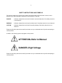
In addition, the following symbol may appear on the product:
ATTENTION–Refer to Manual
DANGER–High Voltage
Please read all safety instructions carefully and make sure you understand them fully before attempting to
use this product.
v
SAFETY WARNINGS AND CLEANING INSTRUCTIONS
DANGER
Opening the cover of this instrument is likely to expose dangerous voltages. Disconnect the
instrument from all voltage sources while it is being opened.
WARNING Using this instrument in a manner not specified by the manufacturer may impair the
protection provided by the instrument.
Cleaning Instructions
To clean the instrument exterior:
! Unplug the instrument from the ac power supply.
! Remove loose dust on the outside of the instrument with a lint-free cloth.
! Remove remaining dirt with a lint-free cloth dampened in a general-purpose detergent and water
solution. Do not use abrasive cleaners.
CAUTION To prevent moisture inside of the instrument during external cleaning, use only enough liquid
to dampen the cloth or applicator.
!
Allow the instrument to dry completely before reconnecting it to the power source.
vi
1
ORTEC MODEL 556
HIGH VOLTAGE POWER SUPPLY
1. DESCRIPTION
The ORTEC 556 High Voltage Power Supply is a
standard double-width NIM module that provides
either polarity of output voltage from 50 to 3000 V,
0 to 10 mA. The adjusted output voltage of the
selected polarity is available simultaneously
through two SHV rear-panel connectors. A rearpanel slide switch permits operation on either 115or 230-V ac input power, furnished through a
removable power line cord and connector.
The 556 features a front-panel LCD meter which
can be programmed via a front-panel toggle switch
to display either output voltage or load current. The
output voltage can be programmed by an external
control via a rear-panel BNC connector.
The 556 provides the extremely stable, low-noise,
high voltage that is required for proper bias of
photomultiplier tubes, ionization chambers, and
semiconductor detectors.
WARNING
DANGER - High Voltage
THIS INSTRUMENT PRODUCES EXTREMELY
HAZARDOUS VOLTAGES AT A POTENTIALLY LETHAL
CURRENT LEVEL. NEVER CONNECT OR DISCONNECT
THE HIGH VOLTAGE OUTPUT CONNECTOR WITH THE
POWER SWITCH ON. NEVER CHANGE THE OUTPUT
POLARITY SWITCH WITH THE POWER SWITCH ON.
ALWAYS SWITCH POWER OFF AND WAIT AT LEAST 30
SECONDS BEFORE CONNECTING OR DISCONNECTING
CABLES AND BEFORE CHANGING THE OUTPUT
POLARITY.
2. SPECIFICATIONS
2.1. PERFORMANCE
OUTPUT POLARITY
Positive or negative,
selected by switch on rear panel.
OUTPUT RANGE 50 to 3000 V; minimum usable
voltage 10 V.
TEMPERATURE INSTABILITY <±50 ppm/°C after
30 minute warmup; operating range 0 to 50°C.
LONG-TERM DRIFT <0.01%/hour and <0.03%/24hour variation in output voltage at constant input
line voltage, load, and ambient temperature after 30
minute warmup.
OUTPUT LOAD CAPACITY 0 to 10 mA.
OUTPUT RIPPLE <10 mV peak-to-peak, 20 Hz to
20 MHZ.
REGULATION <0.0025% variation in output
voltage for combined line and load variations within
operating range at constant ambient temperature.
OVERLOAD PROTECTION Internal circuitry
protects against overloads including short circuits.
2
RESETTABILITY Output voltage can be reset to
within 0.1%.
2.2. CONTROLS
POWER Front-panel switch energizes unit when
power cord is connected to appropriate source, and
an adjacent red LED lamp indicates when power is
applied.
2.4. OUTPUTS
REGULATED DC OUTPUT The adjusted and
regulated voltage, with selected polarity, is
furnished simultaneously to the two SHV
connectors on the rear panel.
2.5. INDICATOR
OUTPUT LEVEL One 6-position switch, one 5position switch, and one 10-turn precision
potentiometer; output level is the sum of the 3
settings.
METER Front-panel LCD display indicates output
voltage in kV ±10 V or load current in mA ±10 A.
Load current is sum of external load current and
internal load current. Internal load resistance is
-5 M .
METER Front-panel switch selects display of output
voltage in kV or load current in mA.
2.6. ELECTRICAL AND MECHANICAL
POLARITY Rear-panel switch selects either
positive or negative output polarity.
POWER REQUIREMENTS 115 or 230 V ac, 47-63
Hz, 70 W nominally.
CONTROL Rear-panel locking switch selects the
reference source for the output voltage.
WEIGHT
Net 3.6 kg (8 lb).
Shipping 4.5 kg (10 lb).
lnt Selects the internal reference source; the frontpanel controls select the output amplitude.
Ext Selects the external reference source; output
voltage is proportional to magnitude of reference
input.
AC VOLTAGE Rear-panel slide switch selects
either 115 V or 230 V ac-input voltage.
2.3. INPUTS
:
S
DIMENSIONS Standard double-width NIM module,
per DOE/ER-0457T.
2.7. ACCESSORIES AVAILABLE
Two 3.66 cm (12 ft) long adapter cables are
available from ORTEC for connecting to the Model
556 SHV output connectors:
1.
AC POWER 103-129 V or 206-258 V, 47-63 Hz,
70 W nominal at full output power; supplied through
international standard IEC power connector on rear
panel. Fuse rating: 1.5 A (FAST) (250V) size 3AG
for 115V or 0.75A(F) (250V) size 5X20 mm for
230V ac operation.
EXTERNAL CONTROL Full range of output
voltage can be based on an external dc reference
level furnished through a rear-panel BNC
connector; control voltage range is 0 through ±6.9
V dc; control voltage polarity must be the same
polarity as that selected by the rear-panel Polarity
switch; this input protected against over-voltages
>±7 V. Input impedance >45 k .
S
2.
ORTEC C-34-12 cable assembly: RG-59 A/U
(75 ) cable with one C-37 SHV female plug
and one C-26 MHV male plug.
ORTEC C-36-12 cable assembly: RG-59 A/U
(75 ) cable with two C-37 SHV female plugs.
S
S
2.8. RELATED EQUIPMENT
Each of the two outputs of the Model 556 can be
used as a power source for any application that is
within the operating limits of the power supply. Both
output levels are identical and of the same polarity.
The load on the Model 556 output circuit is the sum
of the individual loads connected to the output
connectors, and the load current can be monitored
by the front panel LCD meter.
3
This power supply is ideal for use with either one
detector or a pair of detectors where the voltage
level requirements are the same for both detectors.
The appropriate types of detectors for which the
Model 556 is designed include photomultiplier
tubes, ionization chambers, and semiconductor
detectors.
3. INSTALLATION
3.1. GENERAL
The 556 is normally used in conjunction with other
modular electronics and may be installed in a
standard NIM bin such as an ORTEC Model 4001A.
Since the bin may be rack mounted, any high
temperature equipment that may be installed in the
same rack as the bin must be sufficiently cooled by
circulating air to prevent exceeding the +50°C
(120°F) maximum operating temperature of the
556. The ORTEC M127/N NIM Fan is available for
forced-air cooling of a rack of equipment.
3.2. CONNECTION TO POWER
The 556 requires a grounded ac-power source of
nominal 115 V or 230 V ac. A rear panel
international-standard IEC connector allows the
connection of many different types of line cords
between the ac outlet and the 556. A rear-panel
slide switch allows the choice of 115-V or 230-V ac
input voltages. The 556 is shipped with a choice of
two fuse holder caps to accommodate either 3AG
or 5 x 20 mm size fuses. On 115 V ac operation a
1.5 A (FAST) (250V) size 3AG fuse should be used;
on 230 V ac operation, a 0.75A(F) (250V) size 5X20
mm fuse should be used.
This power supply may be operated entirely
removed from the 4001A bin if desired, since it is
totally self-contained and requires no dc-operating
power levels from the NIM bin. However,
precautions should be taken to ensure that
personnel is aware of the shock hazard at the rear
connectors, and that air space should be provided
at the top and bottom of the instrument.
3.3. CONNECTING INTO A SYSTEM
1. Check to see that the power switch is in the Off
position.
2. Check rear panel 115/230 V ac switch and set to
appropriate position.
3. Install a 1.5 A (FAST) (250V) size 3AG for 115V
in gray topped fuse knob or a 0.75A(F) (250V) size
5X20 mm for 230V in black topped fuse knob.
4. Check the polarity switch on the rear panel and
set it for either positive or negative output polarity
as required for the application.
5. Connect a high-voltage cable from either output
connector on the 556 to the instrument to be
powered. Use the other output connector if a
second instrument is to be operated at the same
output voltage.
6. Set the front-panel selector switches and
potentiometer for the desired voltage level. This is
normally specified for the instruments to which the
voltage is to be applied. The adjusted output
voltage will be the sum of the settings of all three
controls.
7. Turn on the power with the switch on the front
panel. The indicator lamp next to the switch will
light to show that input power is being applied. The
indicating meter at the top of the front panel will
also indicate the polarity and amplitude of either the
556 output voltage or load current, depending on
the setting of the meter switch.
3.4. CONNECTING AN EXTERNAL
REFERENCE INPUT
The 556 output voltage level can be controlled by
an external reference level that is furnished through
the rear-panel BNC connector when the Control
locking switch is set at Ext. The range of input
voltage is 0 to 6.9 V to provide an output from 0 to
3000 V. The front- panel voltage level controls are
ineffective for external reference operation.
4
For positive output the polarity selector switch on
the rear panel is set at Pos, and the external
reference should be positive. For negative output
the polarity switch is set at Neg and the external
reference should be negative. The external
reference voltage should be stable and filtered
since the output is linearly proportional to this
reference. The external reference should be
capable of driving the 45-k input impedance.
S
4. CIRCUIT DESCRIPTION
4.1. GENERAL
Figure 4.1. is a simplified block diagram of the 556
circuits.
The 556 requires an ac power input, regardless of
the use of an internal or external reference level.
The selected reference level is applied to a
precision regulator and controls the low voltage
input level to an internal 24-kHz oscillator. The
oscillator output voltage is stepped up for the high
voltage output through a converter transformer, and
this signal is rectified and filtered to produce the
output to each output connector.
The front panel meter (M1) is connected to the
output connectors through R65, R85, and R66 when
monitoring output voltage. R66 is used to calibrate
the front-panel display meter. In the load current
display mode, the output ground return current is
sensed by R69. The sensed voltage is inverted by
S7 and fed to meter M1.
Two feedback loops, one for preregulation and one
for output regulation, operate simultaneously. To
maintain the output voltage at a constant voltage,
U1 compares the sampled output voltage against
the reference voltage appearing at its input
terminals. The resulting error signal is amplified by
U2, Q1, and Q5. The output (emitter) of Q5 feeds
the input of the high frequency dc-to-dc converter.
The converter is made up of a free-running
oscillator (Q6-9) driving chopper MOSFETs Q10
and Q11, which alternately switch on to transfer
energy through high-voltage transformer T2. The
converter output consists of the rectified, filtered,
and doubled high voltage at C17. R53 and C18
further filter the output voltage.
A preregulator circuit is necessary to limit the power
dissipation by Q5. Therefore its collector and
emitter voltages are compared at U3(5 and 6). The
resulting output represents a request for more Q5
collector voltage.
Fig. 4.1. Simplified Block Diagram of ORTEC’s 556 High Voltage Power Supply.
5
U3(1) is synchronized with the power line
frequency. This signal clocks JK flip-flop U4 and
when U3(7) is high, SCR Q12 is fired in
synchronization with the power line through Q2, Q3,
and D8. When SCR Q12 fires, current flows through
R3 and C1, boosting the collector voltage at Q5.
Current limiting transistor Q4 monitors the current
through R4 and prevents damage during output
overload by conducting current away from the base
of Q5. Also, if a high voltage output should become
shorted to ground, transistors Q14 and Q15 will
conduct current away from the base of Q5. Current
pulses in the ground return path during a short
circuit condition produce voltage pulses across R69
which are of sufficient amplitude to turn either Q14
or Q15 On, depending upon the setting of the
POLARITY switch (R.P.). Q15 will become active if
the switch is set for POS and Q14 will be active if
the switch is in the NEG position. Regulators U5
and U6 provide the necessary internal ±12 V power
to operate the control circuitry, the reference circuit,
and the oscillator.
5. CORRECTIVE MAINTENANCE
5.1. GENERAL
5.3. CLEANING INSTRUCTIONS
The 556 should not require maintenance other than
cleaning to prevent leakage paths from being
created by dust collection. If an apparent
malfunction is noted, it is important to determine if
it is within the 556 power supply by disconnecting it
from its load and performing routine diagnostic
tests. The 556 is short-circuit protected, and with a
short-circuit load the output voltage will drop to
zero. If an external short circuit has been applied to
the output, the short circuit must be removed before
the 556 will again produce its adjusted voltage.
To clean the instrument exterior, do the following:
1. Remove loose dust on the outside of the
instrument with a lint free cloth.
2. Remove remaining dirt with a lint free cloth
dampened in a general purpose detergent and
water solution. Do not us abrasive cleaners.
CAUTION: To prevent getting moisture inside of
the instrument during external cleaning, use only
enough liquid to dampen the cloth or applicator.
5.2. TROUBLESHOOTING SUGGESTIONS
5.4. FACTORY REPAIR
Only service technicians trained and experienced in
the service of high-voltage circuitry should attempt
trouble-shooting this unit. EXTREMELY
DANGEROUS VOLTAGE LEVELS ARE PRESENT
INSIDE THE 556 CHASSIS! OBSERVE GREAT
CAUTION WHEN ANY PROTECTIVE COVERS
ARE REMOVED WITH POWER APPLIED!
To troubleshoot the 556, check the internal ±12 V
supplies first, then check for symmetrical
conduction times for oscillator output MOSFETs
Q10 and Q11. With the 556 set for, positive
polarity, the voltages at U1(2 and 3) should be
nearly identical and equal to the reference voltage
setting. If this is not the case, check components
through the two regulating feedback loops
described in Section 4.2.
The 556, or any other standard ORTEC product,
may be returned to the factory for repair service at
a nominal cost. Our standard procedure for repair
ensures the same quality control and checkout that
are used for a new instrument. Always contact
Customer Services at ORTEC, (865) 482-4411,
before sending in an instrument for repair to obtain
shipping instructions and so that the required
Return Authorization Number can be assigned to
the unit. Write this number on the address label and
on the package to ensure prompt attention when it
reaches the factory.