1
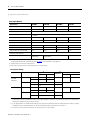
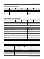
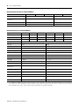
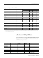
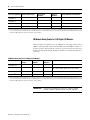
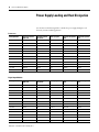
Select SLC 500 I/O Modules
15
AC Input Modules
Specifications
1746-IA4
1746-IA8
1746-IA16
1746-IM4
1746-IM8
1746-IM16
Nominal input
current
12 mA @ 120V AC
Current, off-state
input, max.
2 mA
Inrush current,
max.(1)
0.8 A
Inrush current
time duration,
max.
0.5 ms
0.5 ms
0.5 ms
0.5 ms
0.5 ms
0.5 ms
—
Signal on delay,
max.
35 ms max
35 ms max
35 ms max
35 ms max
35 ms max
35 ms max
15 ms max (DC)
25 ms (AC)
Signal off delay,
max
45 ms max
45 ms max
45 ms max
45 ms max
45 ms max
45 ms max
15 ms max (DC)
25 ms (AC)
12 mA @ 240V AC
2 mA
2 mA
2 mA
1746-IN16
8 mA @ 24V DC
8 mA @ 24V AC
2 mA
2 mA
1 mA (DC)
1 mA (AC)
1.6 A
0.02 A (AC only)
(1) An AC input device must be compatible with SLC 500 input circuit inrush current. A current limiting resistor can be used to limit inrush current. However, the operating
characteristics of the AC input circuit are affected.
AC Output Modules
Specifications
1746-OA8
1746-OA16
1746-OAP12
Number of outptus
8
16
12
Points per common
4
8
6(5)
Voltage category
120/240V AC
Operating voltage range
85…265V AC @ 47…63 Hz
Backplane current (mA) @ 5V
185 mA
370 mA
Backplane current (mA) @ 24V
0 mA
0 mA
0 mA
Voltage drop, on-state output, max
1.50V @ 1.0 A
1.50V @ 0.50 A
1.2V @ 2.0 A
Load current, min
10 mA
10 mA
10 mA
Leakage current, off-state output, max(1)
2 mA
2 mA
2 mA
Surge current per point, max(2)
10 A for 25 ms
Signal on delay, max (resistive load)(3)
1 ms
1 ms
1 ms
Signal off delay, max (resistive load)(5)
11 ms
11 ms
11 ms
Continuous current per point(4)
1.0 A @ 30 °C (86 °F)
0.50 A @ 60 °C (140 °F)
0.50 A @ 30 °C (86 °F)
0.25 A @ 60 °C (140 °F)
2.0 A @ 30 °C (86 °F)
1.25 A @ 55 °C (131 °F)
1.0 A @ 60 °C (140 °F)
Continuous current per module
8.0 A @ 30 °C (86 °F)
4.0 A @ 60 °C (140 °F)
17.0 A for 25 ms(6)
9.0 A @ 30 °C (86 °F)
6.0 A @ 60 °C (140 °F)
(1) To limit the effects of leakage current through solid-state oututs, a loading resistor can be connected in parallel with your load. For 120V AC operation, use a 15 kΩ, 2 W
resistor. For 240V AC operation, use a 15 kΩ, 5 W resistor.
(2) Repeatability is once every 1 s @ 30 °C (86 °F). Repeatability is once every 2 s @ 60 °C (140 °F).
(3) Triac outputs turn on at any point in the AC line cycle and turn off at AC line zero cross.
(4) Recommended surge suppression: For triac outputs when switching 120V AC inductive loads, use Harris Metal-oxide Varistor, model number V220MA2A. Refer to the SLC
500 Modular Hardware Style User Manual, publication 1747-UM011 for more information on surge suppression.
(5) The 1746-OAP12 module features a fused common and blown fuse LED indicator.
Publication 1747-SG001E-EN-E - February 2013
16
Select SLC 500 I/O Modules
(6) Surge current = 35 A per common for 10 ms.
Relay Output Modules
Specifications
1746-OW4
1746-OW8(2)
1746-OW16(2)
1746-OX8(2)
Number of outputs
4
8
16
8
Points per common
4
4
8
Inidvidually isolated
Voltage category
AC/DC Relay
Operating voltage range
5…125V DC
5…265V AC
Backplane current (mA) @ 5V
45 mA
85 mA
170 mA
85 mA
Backplane current (mA) @ 24V
45 mA
90 mA
180 mA
90 mA
Load current, min
10 mA @ 5V DC
Leakage current, off-state output, max
0 mA
0 mA
0 mA
0 mA
Signal on delay, max (resistive load)
10 ms
10 ms
10 ms
10 ms
Signal off delay, max (resistive load)
10 ms
10 ms
10 ms
10 ms
Continuous current per point(1)
See relay contact ratings
Continuous current per module
8.0 A AC
8.0 A/Common
16.0 A AC
8.0 A/Common
(3)
(1) Recommended surge suppression: For triac outputs when switching 120V ac inductive loads, use Harris Metal-oxide Varistor, model number V220MA2A. Refer to the
SLC 500 Modular Hardware Style User Manual, publication 1747-UM011 for more information on surge suppression.
(2) Certified for Class 1 Div 2 Hazardous Locations by CSA.
(3) Limit continuous current per module so that module power does not exceed 1440 VA.
Relay Contact Ratings
Catalog Number
1746-OW4
1746-OW8
1746-OW16
Maximum Volts
AC
DC
1746-OX8
AC
DC
Amperes(1)
Make
Break
240V AC
7.5 A
0.75 A
120V AC
15 A
1.5 A
Amperes(3)
Continuous
Volt-Amperes
Make
Break
2.5 A
1800 VA
180 VA
125V DC
0.22 A(2)
1.0 A
28 VA
24V DC
1.2 A(2)
2.0 A
240V AC
15 A
1.5 A
120V AC
30 A
3.0 A
125V DC
24V DC
5.0 A
3600 VA
0.22 A(2)
1.0 A
28 VA
1.2 A(2)
2.0 A
360 VA
(1) Connecting surge suppressors across your external load extends the life of SLC 500 relay contacts. For recommended surge suppression when switching ac
inductive loads, consult the SLC 500 Modular Hardware Style User Manual, publication 1746-UM011. Recommended surge suppression for switching 24V dc
inductive loads is 1N4004 diode reverse wired across the load.
(2) For dc voltage applications, the make/break ampere rating for relay contacts can be determined by dividing the 28 VA by the applied dc voltage. For example,
28 VA/48V DC= 0.58 A for DC voltage applications less than 14V, the make/break ratings for relay contacts cannot exceed 2 A.
(3) The continuous current per module must be limited so the module power does not exceed 1440 VA.
Publication 1747-SG001E-EN-E - February 2013
Select SLC 500 I/O Modules
19
General Input Specifications for 4-Channel Modules
Specification
1746-NI4
1746-NIO4I
1746-NIO4V
1746-FIO4I
1746-FIO4V
Conversion method
sigma-delta modulation
successive approximation
Converter resolution
16 bit
12 bit
Conversion time
N/A
7.5 μs every 512 μs (nominal)
Module throughput
delay
512 μs (nominal)
1.10 ms (maximum)(1)
512 µs (typical)
(1) Worst-case throughput occurs when the module just misses an event.
Current Loop Input Specifications for 4-Channel Modules
Specification
1746-NI4
1746-NIO4I
1746-NIO4V
1746-FIO4I
1746-FIO4V
Full scale
20 mA
20 mA
20 mA
20 mA
20 mA
Input range
±20 mA (nominal)
±30 mA (maximum)
0…20 mA (nominal)
for 0…30 mA (maximum)
Current input coding
±16,384 for ±20mA
0…2047 counts for 0…20 mA
Absolute maximum
input voltage
±7.5V DC or 7.5V AC RMS
Input Impedance
250 Ω (nominal)
250 Ω (nominal)
Resolution
1.22070 μA per LSB
9.7656 μA per bit
Overall accuracy @
25 °C (77 °F)
±0.365% of full scale
±0.510% of full scale
Overall accuracy,
0…60 °C (32…140
°F)
±0.642% of full scale (maximum)
±0.850% of full scale
Overall accuracy drift
+79 ppm/°C of full scale
+98 ppm/°C of full scale (maximum)
Gain error @ 25 °C
(77 °F)
+0.323% (maximum)
+0.400% (maximum)
Gain error,
0…60 °C (32…140
°F)
+0.556% (maximum)
+0.707% of full scale
Gain error drift
±67 ppm/°C
±89 ppm/°C (maximum)
Voltage Input Specifications for 4-Channel Modules
Specification
1746-NI4
1746-NIO4I
1746-NIO4V
1746-FIO4I
1746-FIO4V
Full Scale
10V DC
10V DC
10V DC
10V DC
10V DC
Input Range
±10V DC -1 LSB
Input Impedance
1 MΩ
Overvoltage Protection (IN+ to -IN)
220V DC or AC RMS continuously
220V dc or ac RMS continuously
Resolution
305.176 μV per LSB
2.4414 mV per LSB (nominal)
Voltage input coding
-32,768…+32,767 for +10V DC
0…4095 counts for 0…10V DC
Overall accuracy @ 25 °C (77 °F)
±0.284% of full scale
±0.440% of full scale
Overall Accuracy, 0…60 °C (32…140 °F)
±0.504% of full scale
±0.750% of full scale
0…10V DC -1 LSB
Publication 1747-SG001E-EN-E - February 2013
20
Select SLC 500 I/O Modules
Voltage Input Specifications for 4-Channel Modules
Specification
1746-NI4
1746-NIO4I
1746-NIO4V
1746-FIO4I
1746-FIO4V
Overall accuracy drift (maximum)
+63 ppm/°C of full scale (maximum)
+88 ppm/°C (maximum)
Gain error @
25 °C (77 °F)
+0.263% (maximum)
+0.323% of full scale
Gain error, 0…60 °C (32…140 °F)
+0.461% (maximum)
+0.530% of full scale
Gain error drift
±57 ppm/°C
±79 ppm?/°C
Output Specifications for 4-Channel Modules
Specification
1746-FIO4I
1746-NIO4I
1746-NO4I
1746-FIO4V
1746-NIO4V
1746-NO4V
Number of outputs
2
2
4
2
2
4
Backplane current (mA) @ 5V
55 mA
55 mA
55 mA
55 mA
55 mA
55 mA
Backplane current (mA) @ 24V
150 mA
145 mA
195 mA(1)
120 mA
115 mA
145 mA
Isolation voltage
Tested @ 500V AC and 710V DC for 60 seconds
Full scale
21 mA
10V DC
Output range (normal)
0…20 mA -1 LSB
±10V DC -1 LSB
Output coding
0…32,764 for 0…21 mA
-32,768…+32,764 for ±10V DC
Output resolution (per LSB)
2.56348 μA
1.22070 mV
Converter resolution
14-bit
14-bit
Conversion method
R-2R ladder
R-2R ladder
Step response
2.5 ms (5…95%)
2.5 ms (normal)
Load range
0…500 Ω
1K…? Ω
Load current, max
N/A
10 mA
Overrange capability
5% (0…21 mA -1 LSB)
N/A
Overall accuracy @
25 °C (77 °F)
±0.298% of full scale
±0.208% of full scale
Overall Accuracy,
0…60 °C (32…140 °F)
±0.541% of full scale
±0.384% of full scale
Overall accuracy drift, max
±70 ppm/°C of full scale
±0.384% of full scale
Gain error @ 25 °C (77 °F)
±298% of full scale
±208% of full scale
Gain Error, 0…60 °C
(32…140 °F)
±516% of full scale
±374% of full scale
Gain error drift, max
±62 ppm/°C of full scale
±47 ppm/°C of full scale
(1) The 1746-NO4I and 1746-NO4V analog output modules have connections for user-supplied 24V dc power supplies. When external 24V DC power is used, the module only
draws 5V DC current from the SLC backplane. If an external 24V DC power supply is required, the tolerance must be 24V ±10% (26.6…26.4V DC). The user power supplies
for SLC 500 modular systems, 1746-P1, 1746-P2, 1746-P5, and 1746-P6 power supplies do not meet this specification.
Publication 1747-SG001E-EN-E - February 2013
Select SLC 500 I/O Modules
45
Relay Master and Expander 40-Terminal XIMs
Description
Catalog Number
I/O Module Catalog Number 1746IB32
IV32
OB32
OB32E
OV32
Relay Master
40-pin master with eight (8) 24V DC relays
1492-XIM4024-8R
–
–
H
H
–
40-pin master with sixteen (16) 24V DC relays
1492-XIM4024-16R
–
–
H
H
–
40-pin master with sixteen (16) 24V DC relays with
fusing
1492-XIM4024-16RF
–
–
H
H
–
Expander with eight (8) 24V DC relays
1492-XIM24-8R
–
–
(1)
(1)
–
Expander with eight (8) 120V AC relays
1492-XIM120-8R
–
–
–
–
–
–
–
(2)
(2)
–
Relay Expander
Expander with sixteen (16) 24V DC relays with fusing 1492-XIM24-16RF
Fusible Expander
8-channel expander with 24V DC blown fuse
indicators
1492-XIMF-F24-2
–
–
(1)
(1)
–
8-channel expander with 120V AC blown fuse
indicators
1492-XIMF-F120-2
–
–
–
–
–
1492-XIMF-2
–
–
(1)
(1)
–
Feed-through Expander
Expander with eight (8) feed-through channels 132V
AC/DC max
(1) Two or three expanders can be connected to a master to provide a total of 32 outputs. An extender cable is included with each expander to connect it to the master.
(2) Can have one expandable module per master.
Pre-Wired Cables for 1746 Digital I/O Modules
These pre-wired cables have a pre-wired removable terminal block (RTB) on one end to
connect to the front of a Bulletin 1746 digital I/O module and a connector on the other
end to plug into a 20- or 40-terminal IFM/XIM. You must first select the IFM/XIM
from one of the preceding selection tables.
Cable Catalog Number
Standard Cable Lengths
Build to Order
Available
Number of
Conductors
Mating I/O Module Catalog Number
1492-CABLE(1)A
0.5, 1.0, 2.5, 5.0 m
Yes
20
1746-IA16, -IM16
1492-CABLE(1)B
0.5, 1.0, 2.5, 5.0 m
Yes
20
1746-IB16, -IH16, -IN16, -ITB16, -ITV16
1492-CABLE(1)C
0.5, 1.0, 2.5, 5.0 m
Yes
20
1746-OA16
1492-CABLE(1)CR
0.5, 1.0, 2.5, 5.0 m
Yes
20
1746-OA16
1492-CABLE(1)D
0.5, 1.0, 2.5, 5.0 m
Yes
20
1746-OW16, -OX8
1492-CABLE(1)E
0.5, 1.0, 2.5, 5.0 m
Yes
20
1746-IG16, -OB16, -OB16E, -OBP16,
-OG16, -OV16, -OVP16
Publication 1747-SG001E-EN-E - February 2013
46
Select SLC 500 I/O Modules
Cable Catalog Number
Standard Cable Lengths
Build to Order
Available
Number of
Conductors
Mating I/O Module Catalog Number
1492-CABLE(1)G
0.5, 1.0, 2.5, 5.0 m
Yes
20
1746-OA16
1492-CABLE(1)H
0.5, 1.0, 2.5, 5.0 m
Yes
20
1746-IB32, -IV32, -OB32, -OB32E, -OV32
1492-CABLE(1)N
0.5, 1.0, 2.5, 5.0 m
Yes
20
1746-OW16, -OX8
1492-CABLE(1)S
0.5, 1.0, 2.5, 5.0 m
Yes
20
1746-OX8
(1) Cables are available in standard lengths of 0.5 m, 1.0 m, 2.5 m, and 5.0 m. To order, insert the code for the desired cable length into the cat. no. (005 = 0.5 m, 010 = 1.0 m,
025 = 2.5 m, and 050 = 5.0 m). Example: Cat. No. 1492-CABLE005N is for a 0.5 m cable that could be used to connect a catalog number 1492-IFM20D24N IFM to a Catalog
Number 1746-OW16 I/O module. Build-to-order lengths are also available.
I/O Module-Ready Cables for 1746 Digital I/O Modules
The I/O module-ready cables have a pre-wired RTB on one end to plug onto the front of
a Bulletin 1746 I/O module and 20 or 40 individually colored #18 AWG conductors on
the other end. These cables provide the convenience of pre-wired connections at the I/O
module end, while still allowing the flexibility to fieldwire to standard terminal blocks of
your choice.
I/O Module-Ready Cables for 1746 Digital I/O Modules
Cable Catalog Number
Standard Cable
Lengths
Build to Order
Available
Number of
Conductors
Mating I/O Module Catalog Number
1492-CABLE(1)N3
1.0, 2.5, 5.0 m
Yes
40
1746-IB32, -IV32, -OB32, -OV32, -OB32E
1492-CABLE(1)RTBB
1.0, 2.5, 5.0 m
Yes
20
1746-IB16, -IC16, -IG16, -IH16, -IN16, -ITB16, -ITV16, -IV16,
-OB16, -OB16E, -OBP8, -OBP16, -OG16, -OV16, -OVP16
1492-CABLE(1)RTBO
1.0, 2.5, 5.0 m
Yes
20
1746-OW16, -OX8
1492-CABLE(1)RTBR
1.0, 2.5, 5.0 m
Yes
20
1746-IA16, -OA16, -OAP12, -IM16
(1) Cables are available in standard lengths of 0.5 m, 1.0 m, 2.5 m, and 5.0 m. To order, insert the code for the desired cable length into the cat. no. (005 = 0.5 m, 010 = 1.0 m,
025 = 2.5 m, and 050 = 5.0 m). Example: Cat. No. 1492-CABLE005N is for a 0.5 m cable that could be used to connect a catalog number 1492-IFM20D24N IFM to a Catalog
Number 1746-OW16 I/O module. Build-to-order lengths are also available.
IMPORTANT
Publication 1747-SG001E-EN-E - February 2013
The following I/O Modules do not have RTBs: 1746-IA4, 1746-IA8,
1746-IB8, 1746-IM4, 1746-IM8, 1746-IV8, 1746-OA8, 1746-OB8.
84
Select SLC 500 Power Supplies
Power Supply Loading and Heat Dissipation
Use the values in the following tables to calculate the power supply loading for each
chassis in your SLC modular application.
Processors
Catalog Number
Backplane Current
(mA) @ 5V
Backplane Current
(mA) @ 24V
Watts per point
Thermal dissipation,
min.
Thermal dissipation,
max.
1747-L511
90 mA
0 mA
N/A
1.75 W
1.75 W
1747-L514
90 mA
0 mA
N/A
1.75 W
1.75 W
1747-L524
350 mA
105 mA
N/A
1.75 W
1.75 W
1747-L531
500 mA
175 mA
N/A
1.75 W
1.75 W
1747-L532
500 mA
175 mA
N/A
2.90 W
2.90 W
1747-L533
500 mA
175 mA
N/A
2.90 W
2.90 W
1747-L541
1000 mA
200 mA
N/A
4.00 W
4.00 W
1747-L542
1000 mA
200 mA
N/A
4.00 W
4.00 W
1747-L543
1000 mA
200 mA
N/A
4.00 W
4.00 W
1747-L551
1000 mA
200 mA
N/A
4.00 W
4.00 W
1747-L552
1000 mA
200 mA
N/A
4.00 W
4.00 W
1747-L553
1000 mA
200 mA
N/A
4.00 W
4.00 W
Catalog Number
Backplane Current
(mA) @ 5V
Backplane Current
(mA) @ 24V
Watts per point
Thermal dissipation,
min.
Thermal dissipation,
max.
1746-IA4
35 mA
0 mA
0.270 W
0.175 W
1.30 W
1746-IA8
50 mA
0 mA
0.270 W
0.250 W
2.40 W
1746-IA16
85 mA
0 mA
0.270 W
0.425 W
4.80 W
1746-IB8
50 mA
0 mA
0.200 W
0.250 W
1.90 W
1746-IB16
50 mA
0 mA
0.200 W
0.425 W
3.60 W
1746-IB32(1)
106 mA
0 mA
0.200 W
0.530 W
6.90 W
1746-IC16
50 mA
0 mA
0.220 W
0.425 W
3.95 W
1746-IG16
140 mA
0 mA
0.270 W
0.700 W
1.00 W
1746-IH16
85 mA
0 mA
0.320 W
0.675 W
3.08 W
1746-IM4
35 mA
0 mA
0.350 W
0.175 W
1.60 W
1746-IM8
50 mA
0 mA
0.350 W
0.250 W
3.10 W
1746-IM16
85 mA
0 mA
0.350 W
0.425 W
6.00 W
1746-IN16
85 mA
0 mA
0.350 W
0.425 W
6.00 W
1746-ITB16
50 mA
0 mA
0.200 W
0.425 W
3.625 W
Digital Input Modules
Publication 1747-SG001E-EN-E - February 2013