1
SIRIUS89N
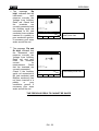
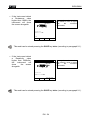
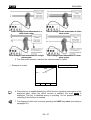
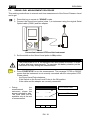
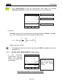
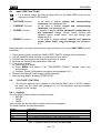
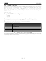
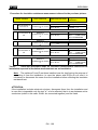
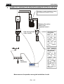
Check the continuity among:
a) earth poles of all the plugs and earth collector or node.
b) earth terminals of class I instruments (Boiler etc.) and earth collector or node.
c) main external masses (water, gas pipes etc.) and earth collector or node.
d) auxiliary external masses to the earth terminal.
ALLOWABLE VALUES
The standards CEI 64-8/6 do not give any indication on the maximum resistance values
which cannot be overcome, in order to be able to declare the positive outcome of the
continuity test.
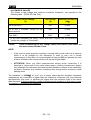
The standard CEI 64-8/6 simply requires that the instrument in use warns the operator if
the test was not carried out with a current of at least 0.2 A and an open circuit
voltage ranging from 4 V to 24 V.
The resistance values can be calculated according to the sections and lengths of the
conductors under test, anyway if the instrument detects values of some ohm the test
can be considered as passed.
16.2.
Insulation Resistance Measurement of the Electrical Installations (250Vdc,
500Vdc, 1000Vdc)
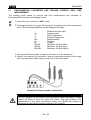
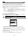
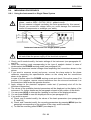
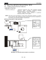
PURPOSE OF THE TEST
Check that the insulation resistance of the installation complies with the requirements
of standards CEI 64-8/6.
NOTA: This test is to be effected on an open circuit with any load disconnected.
INSTALLATION PARTS TO BE CHECKED
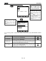
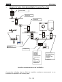
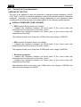
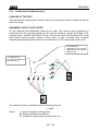
a) Between each active conductor and the earth (the neutral conductor is considered
an active conductor except in the case of TN-C systems where it is considered
part of the earth (PEN).
During this measurement all active conductors can be connected to each other, in
case the measurement result does not fall within the standard limits the test is to be
repeated for each single conductor.
b) Among active conductors.
The standard CEI 64-8/6 recommends to check the insulation among the active
conductors when this is possible (ATTENTION).
EN - 107