1
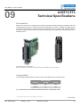
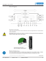
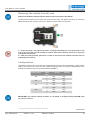
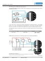
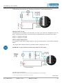
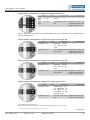
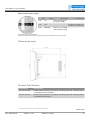
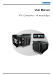
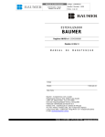
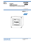
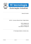
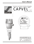
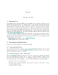
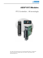
AIO571/573 Modules
P7C Controller – HI tecnologia
The content of this document is part of P7C User Manual (PMU1070011). The Notes and
Acronyms full list is at the complete version of the manual. To get it, please, access:
www.hitecnologia.com.br
User Manual - P7C Controller
09
AIO571/573
Technical Specifications
Presentation
AIO571/573 are the P7C1 analog inputs, outputs and pt100 channels modules, providing to the user
4 analog inputs channels of 10 bits1 resolution (configurable for current or voltage), 2 analog outputs
of 10 bits1 resolution and 2 channels with inputs for pt100 (3 wires), all them with individual leds to
indicate the status leds. Module with automatic addressing, being allowed the simultaneous use of
modules at P7C1.
Compatible with the module AIO571
Note: The modules can have lever connectors (for the new modules) or screw connectors.
Compatibility
The following table presents the CPU modules compatible with the modules used:
P7C Controller
Module
CPU300
CPU301
AIO571*
Yes
Yes
AIO573
No
Yes
(*) – It must not be used with controllers that have 2 expansion racks
1 - Check the Notes and Acronysms List at the beggining of this document
Ref.: PMU107001
Version: 1.0.07
Release: 10/20/10
AIO571/573
70
User Manual - P7C Controller
Technical Specifications
Power Supply
5 Vdc (supplied by main rack)
Consumption
0,7 W
Operation temperature
0 to 60 °C
Storage temperature
-25 °C to 80 °C
Humidity
≤90% without condensation
Module weight
0,06 Kg approximately
Dimensions
85 (W) x 83 (H) x 27 (L) mm
Technical Data – Input / Output
PT100 input
2 pt100 (3 wires) sensor channels, with the standard
operation range of -10 ... +150 °C.
Reading maximum error 0,5% full scale
Analog input
4 10 bits1 resolution channels with option of connections with signals from 0 to 20 mA1, 4 a 20 mA1 (impedance1 of 125 Ω) and 0 to 10 Vdc (impedance1
of 10 KΩ)
Analog input protection
Against overvoltage
Analog output
2 10 bits1 resolution channels for signals from 0 to 20
mA1 or 4 to 20 mA1
Analog output protection
Short-circuit protected
Process Interface
Compatible with the module AIO571
Note: The modules can have lever connectors (for the new modules) or screw connectors.
1 - Check the Notes and Acronysms List at the beggining of this document
Ref.: PMU107001
Version: 1.0.07
Release: 10/20/10
AIO571/573
71
User Manual - P7C Controller
Connections
The modules AIO571/573 have two process interface connectors1, identified as X1 (8 terminal
blocks1) and X2 (8 terminal blocks1). These terminal blocks1 are numbered as the following tables
will show:
X1 Terminal Block1
Signal
1
E0 temperature sensor negative input
2
E0 temperature sensor positive input
3
E1 temperature sensor negative input
4
E1 temperature sensor positive input
5
Analog inputs reference (0V)
6
E2 analog input channel
7
E3 analog input channel
8
E4 analog input channel
X2 Terminal Block1
Signal
1
E5 analog input channel
2
Analog inputs reference (0V)
3
S0 analog output channel
4
S0 analog output channel
5
Analog outputs reference (0V)
6
Analog outputs supply
7
Analog outputs power supply reference
8
Cable shielding
IMPORTANT: The analog outputs need an external 24Vdc power supply, that can be connected at the terminal blocks1 X2-6 (24vdc) and X2-7 (0V).
For analog signals, use cables with shielding, connecting them to the terminal block1 X2-8.
1 - Check the Notes and Acronysms List at the beggining of this document
Ref.: PMU107001
Version: 1.0.07
Release: 10/20/10
AIO571/573
72
User Manual - P7C Controller
Block Diagram
Ground connector
There are two ground connectors at the module side, which are responsible for the contact with the
main rack structure.
IMPORTANT: When handling the module, be careful to not hurt yourself with the ground connectors, because they have a sharp surface.
Compatible with the module AIO571
Note: The modules can have lever connectors
(for the new modules) or screw connectors.
Module Addressing
The modules AIO571/573 have not addressing configuration using hardware (strap1 / switch).
It is provided automatically by the controller firmware when connected to the rack.
1 - Check the Notes and Acronysms List at the beggining of this document
Ref.: PMU107001
Version: 1.0.07
Release: 10/20/10
AIO571/573
73
User Manual - P7C Controller
Removing the module from the rack
AIO571/573 modules CAN be replaced with the device turned on (Hot Swap1).
To remove the module from the main rack, push the two locks, one against the other, to unlock the
plastic frontal. At this moment, pull them in order to remove them from the rack.
1º - Press the locks, one against the other, using the two hands (it is not necessary to use
a lot of force for that, just the enough to unlock. Each lock needs be moved at +/- 3mm (as
indicated at the picture).
2º - With the locks pressed, pull them in order to disconnect the module from the rack (as
indicated at the picture).
Configurations
The analog inputs E2, E3, E4 and E5 are configurable by using a keys set available on a Dip Switch1
(SW1). The access to the keys is at the module component face. The others configurations of the
module are executed using an specific software (SPDSW1).
Analog Input
DIP8
SW1
E2
1
ON
OFF
2
OFF
ON
3
ON
OFF
4
OFF
ON
5
ON
OFF
6
OFF
ON
7
ON
OFF
8
OFF
ON
E3
E4
E5
Current
Voltage
IMPORTANT: The current offset 0 to 20mA1 or 4 to 20mA1 is configured using SPDSW1 from
the version 2.x.xx on
1 - Check the Notes and Acronysms List at the beggining of this document
Ref.: PMU107001
Version: 1.0.07
Release: 10/20/10
AIO571/573
74
User Manual - P7C Controller
Pt100 Inputs utilisation examples
The inputs E1 and E0 connection scheme, when connected to the sensor pt100 (3 wires), will be
exemplified as it follows:
In this case, the PLC1 will be able to read the temperature at channels E0 and E1. The standard
range is -10 to +150ºC, and full scale can be calibrated from -120 to +250ºC. The reading maximum
error is 0,5% full scale. The Pt100 second negative input must be connected to signal 0V (X1-5).
The temperature values provided by the module for the Ladder program are set in Celsius degrees
x 10, thus:
Standard Temp. [ºC]
Value obtained from Ladder program
Description
-10 to +150
-100 to 1500
-100 = -10.0ºC
1500 = 150.0ºC
Utilisation examples of analog inputs of instrumentation
Compatible with the module AIO571
Note: The modules can have lever connectors (for the new modules) or screw connectors.
1 - Check the Notes and Acronysms List at the beggining of this document
Ref.: PMU107001
Version: 1.0.07
Release: 10/20/10
AIO571/573
75
User Manual - P7C Controller
Utilisation examples of analog outputs of instrumentation
Operation from 0 to 10V
The analog input can operate on a range from 0 to 10V. In this case, the configuration from 0 to
20mA1 must be kept and it also must be closed the configuration strap associated to the output.
Strap J3 – Related to S0 output
Strap J4 – Related to S1 output
Others voltage configurations
It is possible to obtain other voltage ranges by using an external resistor, as the following example
shows:
- By using a 250Ω external resistor it is possible to obtain a range from 0 to 5V.
ATTENTION: To use an external resistor, keep straps J3 and J4 open.
Compatible with the module AIO571
Note: The modules can have lever connectors (for the new modules) or screw connectors.
1 - Check the Notes and Acronysms List at the beggining of this document
Ref.: PMU107001
Version: 1.0.07
Release: 10/20/10
AIO571/573
76
User Manual - P7C Controller
Process interface leds operation
pt100 inputs, configured at the range from -10 to +150ºC
Leds
Status
Condition
Diagnosis
E(0 and 1) On
pt100 sensor con- Operational channel
nected
E(0 and 1) Off
pt100 sensor nega- Sensor fail, discontive input discon- nected,
equipment
nected
turned off or analog
module parameterization fail
Analog inputs, configured for current at the range from 4 to 20 mA1
Leds
Status
Condition
Diagnosis
E(2 and 5) On
There is current sig- Operational channel
nal at the input
E(2 and 5) Off
There is no current
signal at the input
or current smaller
then the range configured
Open channel, equipment turned off or parameterization fail of
the analog module
Analog inputs, configured for current at the range from 0 to 20 mA1
Leds
Status
Condition
Diagnosis
Operational channel
E(2)
E(5)
to On
*Note1
E(2)
E(5)
to Off
Inoperational chan- Equipment turned off
nel
or parameterization fail
of the analog module
*Note1: When the channel off-set (Current/Voltage) is zero, the condition “led on” indicates that the
channel is operational.
Analog inputs, configured for voltage at the range from 2 to 10V
Leds
Status
Condition
E(2 and 5) On
There is voltage
signal at the input
E(2 and 5) Off
There is no voltage
signal at the input
or voltage smaller
then the range configured
Diagnosis
Open channel, equipment turned off or parameterization fail of
the analog module
Compatible with the module AIO571
Note: The modules can have lever connectors (for the new modules) or screw connectors.
1 - Check the Notes and Acronysms List at the beggining of this document
Ref.: PMU107001
Version: 1.0.07
Release: 10/20/10
AIO571/573
77
User Manual - P7C Controller
Analog inputs, configured for voltage at the range from 0 to 10 V
Leds
Status
Condition
Diagnosis
E(2)
E(5)
to On
*Note1
E(2)
E(5)
to Off
Inoperational chan- Equipment turned off
nel
or parameterization fail
of the analog module
*Note1: When the channel off-set (Current/Voltage) is zero, the condition “led on” indicates that the
channel is operational.
Analog outputs, configured for current at the range from 4 to 20 mA1
Leds
Status
Condition
Diagnosis
S (0 and 1) On
Detected connection with the process
S (0 and 1) Off
No connection with Equipment turned off
the process
or parameterization fail
of the analog module
Analog outputs, configured for current at the range from 0 to 20 mA1
Leds
Status
Condition
Diagnosis
S (0 and 1) On
Detected connection with the process
S (0 and 1) Off
No connection with Equipment turned off
the process
or parameterization fail
of the analog module
Analog outputs, configured for voltage at the range from 0 to 10 V
Leds
Status
Condition
Diagnosis
S (0 and 1) On
Continuously ON,
not depending on
the output (if it is
connected to the
process or not)
S (0 and 1) Off
No 24V power sup- Equipment turned off or
ply
module not operational
Compatible with the module AIO571
Note: The modules can have lever connectors (for the new modules) or screw connectors.
1 - Check the Notes and Acronysms List at the beggining of this document
Ref.: PMU107001
Version: 1.0.07
Release: 10/20/10
AIO571/573
78
User Manual - P7C Controller
24Vdc module power supply
Leds
Status
Condition
24V
On
There is analog output power supply
24V
Off
24V
Blinking
Diagnosis
Equipment turned off or
module not operational
There is no analog
output power supply
Compatible with the module AIO571
Note: The modules can have lever connectors (for the new modules) or screw connectors.
Dimensions (mm)
Product Part Number
Part Number
Identification
300.107.571.000
Module with 2 pt100 (3 wires) inputs, 4 analog inputs and 2 analog outputs
(compatible with CPU300/301)
300.107.573.000
Module with 2 pt100 (3 wires) inputs, 4 analog inputs and 2 analog outputs
(compatible with CPU301)
1 - Check the Notes and Acronysms List at the beggining of this document
Ref.: PMU107001
Version: 1.0.07
Release: 10/20/10
AIO571/573
79