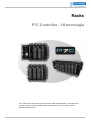
1
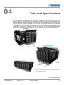
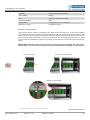
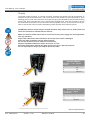
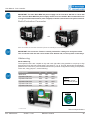
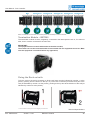
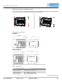
Racks
P7C Controller – HI tecnologia
The content of this document is part of P7C User Manual (PMU1070011). The Notes and
Acronyms full list is at the complete version of the manual. To get it, please, access:
www.hitecnologia.com.br
User Manual - P7C Controller
04
Technical Specifications
Presentation
P7C1 programmable controllers line was developed for attending machine and process control applications. This PLC1 has up to 368 I/O1 points at its full configuration and offers all the others HI controllers versatility, including also new and exclusive features. Its design is based on expansible racks,
supporting up to 4 hardware modules per rack. The basic configuration is composed by a main rack
with power supply and capacity up to 4 modules. On the other hand, the Full configuration can be
composed by 1 main rack + 5 expansion racks, providing 24 slots1 for use. The racks interconnection
must be done always on the right side of the rack, using the connector1 placed at the backplane1.
Note: The modules can have lever connectors (for the new modules) or screw connectors.
1 - Check the Notes and Acronysms List at the beggining of this document
Ref.: PMU107001
Version: 1.0.07
Release: 10/20/10
Technical Specifications
31
User Manual - P7C Controller
Applicable Standards
P7C1 controller was developed for attending CE certification requirements, being adherent to the
standards defined by IEC61131-2. According to the criterion defined by IEC61131-2, the equipment
is able to operate on the named “Zone B”, attending to the specification of the following standards:
Standards
Name
CISPR11, CISPR16-1
Irradiated interference
CISPR11, CISPR16-1 and CISPR16-2
Conducted interference
IEC61000-4-2
Electromagnetic discharge immunity
IEC61000-4-3
Irradiated eletromagnetic fields immunity
IEC61000-4-4
Fast transients immunity
IEC61000-4-5
Immunity against high energy outbreaks
IEC61000-4-6
Immunity against conducted radiofrequency
IEC61000-4-8
Immunity against electromagnetic fields
Technical Data – Main Rack AC (300.107.200.000)
Power Supply AC (PWS800)
85 to 265 VAC or 100 to 400 VDC automatic
Consumption
25 Watts máx
Operating temperature
0 to 60 Cº
Storage temperature
-25 Cº to 80 Cº
Humidity
≤90% without condensation
Rack weight
1,0 Kg approximately
Box
Aluminium and Carbon Steel
Protection Degree
IP30
Dimensions
150 (W) x 110 (H) x 115 (L) mm
Technical Data – Main Rack DC (300.107.200.010)
Power Supply DC (DCC850)
10 to 36 VDC automatic
Consumption
30 Watts máx
Operating temperature
0 to 60 Cº
Storage temperature
-25 Cº to 80 Cº
Humidity
≤90% without condensation
Rack weight
1,0 Kg approximately
Box
Aluminium and Carbon Steel
Protection Degree
IP30
Dimensions
150 (L) x 110 (A) x 115 (P) mm
Technical Data – Expansion Rack (300.107.200.100)
Power Supply
Supplied by main rack
Consumption
-
Operating temperature
0 to 60 Cº
Storage temperature
-25 °C to 80 °C
1 - Check the Notes and Acronysms List at the beggining of this document
Ref.: PMU107001
Version: 1.0.07
Release: 10/20/10
Technical Specifications
32
User Manual - P7C Controller
Humidity
≤90% without condensation
Rack weight
0,5 Kg
Box
Aluminium and Carbon Steel
Protection Degree
IP30
Dimensions
110 (W) x 110 (H) x 115 (P) mm
Maximum number
5 expansion racks
Racks connection
The expansion racks must be connected to the right side of the main rack. In the case of adding
one expansion rack, it is necessary to remove the screw place at the main rack side (Picture A), and
loosen the two screws placed on the rack back side, in order to fit the (red) locks, as shown on the
picture (Picture B) and there the connection will be made. For that, approach both racks, in order
to fit the locks and connectors1 together. Push both screws (M3x4) to fix the two locks as Picture C
shows.
IMPORTANT: Note the perfect racks connection: they must be aligned after the correct connection. The incorrect connection may result in bad performance or damages to the product.
Picture A: Screw
Picture B: Locks / Screws
Picture C: Connection
1 - Check the Notes and Acronysms List at the beggining of this document
Ref.: PMU107001
Version: 1.0.07
Release: 10/20/10
Technical Specifications
33
User Manual - P7C Controller
Supply
The power supply connector1 is a spring connector1 that does not need a screw to be tightened. To
insert the wire in the terminal block1, use a screw-driver at the smaller hole (as indicated by A, at the
following picture). Push the screw-driver until open the spring (as indicated by letter B at the following
picture) and, after, insert the wire in the corresponding terminal block1. After this procedure, remove
the screw-driver and make sure the connection was completed correctly. To remove the wire is possible to execute the same procedure indicated by letters A and B of the following picture.
ATTENTION: Electric-shock danger: the bad utilisation may result in fire or death. Read and
follow the instructions indicated at this manual:
Make sure that the cables which will be connected to the power supply are disenergized before any operation;
Inspect the cable before each utilisation. Do not use if the cable is damaged.
Insert the cable completely into the terminal block1;
Do not use excessive force to make the connections;
Keep the equipment away from water. Do not use it if wet;
Avoid the overheating. Unwind the cable and do not cover it with any material;
Do not superimpose, drag or put objects above the cable;
AC Rack (PWS800)
Terminal
nector1
Con- Signal
1
AC
2
AC
3
Ground
DC Rack (DCC850)
T e r m i n a l Signal
Connector1
1 - Check the Notes and Acronysms List at the beggining of this document
Ref.: PMU107001
Version: 1.0.07
Release: 10/20/10
1
-
2
+
3
Ground
Technical Specifications
34
User Manual - P7C Controller
IMPORTANT: The main Rack MRK AC power supply can be from 85 to 265 VAC or 100 to 400
VDC. The main Rack MRK DC power supply can be from 10 to 36VDC. We recommend the use
of a rigid or flexible 2,5mm2 wire (7mm stripped) or flexible 1,5mm2 wire with eyelets terminal.
Earth-Protection Connector
OR
Note: The modules can have lever connectors (for the new modules) or screw connectors.
IMPORTANT: Use connector1 Faston 6.3 totally isolated for 1mm2 green and yellow cable.
This connection with the rack can be made at the bottom side, on the top side or both ways.
Addressing
Racks addresing
The expansion racks are coupled on the main rack right side, being possible to couple up to five
expansions. Each rack has a three straps1 set named J1, J2, J3. This set, placed at the backplanes1,
(between the connectors1 of the third and fourth slots1) must be configured according to the position
of the rack, using jumpers1, as the following:
Identification
J1
J2
J3
Main Rack
OFF
OFF
OFF
Expansion Rack 01
ON
OFF
OFF
Expansion Rack 02
OFF
ON
OFF
Expansion Rack 03
ON
ON
OFF
Expansion Rack 04
OFF
OFF
ON
Expansion Rack 05
ON
OFF
ON
Caption:
ON: with jumper1
OFF: without jumper1
Caption:
1 - Check the Notes and Acronysms List at the beggining of this document
Ref.: PMU107001
Version: 1.0.07
Release: 10/20/10
Technical Specifications
35
User Manual - P7C Controller
Note: The modules can have lever connectors (for the new modules) or screw connectors.
Termination Module – BBT260
The termination module must be, obligatorily, connected to the last expansion rack or, if it does not
exist, then it must be connected to the main rack.
IMPORTANT:
The equipment does not work without the termination module;
The module can not be connected and/or disconnected with the equipment turned on. Make
sure the equipment is turned off before any opperation;
Fixing the Rack on trails
To fix the rack on the trail is necessary to fit the rack lower part (as indicated by number 1, at the
picture), pushing from the bottom to the top. To put the rack in the trail just fit the lower part of the
rack (as indicated by number 1 at the picture), pushing to the top and at the direction of the trail (as
indicated by number 2 at the picture):
1 - Check the Notes and Acronysms List at the beggining of this document
Ref.: PMU107001
Version: 1.0.07
Release: 10/20/10
Technical Specifications
36
User Manual - P7C Controller
Removing the rack from trails
To remove the rack from the trail, just push it to the top (as indicated by number 1, at the picture) and
also move it to the front (as indicated by number 2, at the picture):
Dimensions (mm)
Main Rack
Expansion Rack
Note: The modules can have lever connectors (for the new modules) or screw connectors.
Part Number
Code
Identification
300.107.200.000
P7C1 MRK AC main rack
300.107.200.010
P7C1 MRK DC main rack
300.107.200.100
P7C1 XRK expansion rack
1 - Check the Notes and Acronysms List at the beggining of this document
Ref.: PMU107001
Version: 1.0.07
Release: 10/20/10
Technical Specifications
37