1
NUFLOTM
Scanner 1140
RTU Hardware
User Manual
© 2010 Cameron International Corporation (“Cameron”). All information contained in this publication is
confidential and proprietary property of Cameron. Any reproduction or use of these instructions, drawings, or
photographs without the express written permission of an officer of Cameron is forbidden.
All Rights Reserved.
Printed in the United States of America.
Manual No. 9A-30165006, Rev. 02
August 2010
Warranty
The Company warrants all products of its manufacture and bearing its nameplate for a period of one year after date of
shipment from its factory to be free from defects in material and workmanship subject to the following:
The Company’s liability under this warranty is limited, in the sole and absolute discretion of the Company, to refunding
the purchase price, to repairing, or to replacing parts shown to the satisfaction of the Company to have been defective
when shipped and then only if such defective parts are promptly delivered to its factory, transportation charges prepaid.
This warranty is void if written notification is not given by Purchaser to Company within one year after said date of
shipment.
This warranty applies only if the products have been installed, operated and maintained in accordance with the
Company’s recommendations and the products have not been misused, neglected, damaged by flood, fire or act of God,
or modified or repaired, other than by the Company.
Where the Company has manufactured the products to a design of the purchaser, no liability is accepted by the
Company for design errors, which remain the responsibility of the Purchaser.
This warranty is expressly in lieu of all other warranties, obligations, conditions or liabilities, expressed or implied by
the Company or its representative. All statutory or implied warranties and conditions, other than title, are hereby
expressly negated and excluded. The Company’s liability as stated herein cannot be altered, enlarged or extended
except in writing by an officer of the Company. The Company shall be under no liability in contract or otherwise for
any loss, damage, death or injury arising directly or indirectly out of the supply, failure to supply, or use of the
products.
Replacement parts will be invoiced in the regular way with invoices subject to adjustment after the parts claimed
defective are examined at our factory. The Company reserves the right to make such changes in details of design,
construction of product arrangement as shall, in its judgment, constitute any warranty of the Company’s supplier of
such products.
The Company and its representatives will furnish, upon request, data and engineering services relating to the
application or use of its products. It will not be responsible and it does not assume any liability whatsoever for
damages of any kind sustained either directly or indirectly by any person in the adoption or use of such data, any errors
or omissions in such data, or engineering services in whole or in part.
Warranty Limitation
The Company manufactures products which satisfy the exact definition of Quality, that is, they meet the specifications
as advertised or as stated by our customer. The products are intended to be used in accordance with the specification
and applications described in this document.
A limited warranty applies to Products manufactured by Cameron’s Measurement Systems Division. The Company
will assume responsibilities for obligations, related to its products, which are specifically noted within the written
warranty for a specific product. However, the Company will not be liable for any loss, damage, cost of repairs,
incidental or consequential damages of any kind whether or not they are based upon expressed or implied warranty,
contract, negligence, or strict liability arising in connection with the design, manufacture, sale use or repair of the
products, if they are used outside the constraints of recommended usage as set forth herein.
Any use or application that deviates from the stated performance specification is not recommended and could render
the instrument unsafe.
The Company should be advised of any apparent deviation or deficiency from specifications including safety related
deficiencies. A return authorization will be issued, where applicable, for goods returned for inspection, calibration or
repair, under warranty.
iii
Product Warranty Statement
The warranty applicable to this product is stated at the beginning of this manual.
Should any problem arise after-delivery, please contact Cameron’s Measurement Systems Division HelpDesk at
1-877-805-7226 or the Customer Service department during normal business hours at (403) 291-4814.
Before installing the instrument, become familiar with the installation instructions presented in this document.
Also, be aware of the following important notices that appear throughout the manual:
WARNING notes indicate the presence of a hazard that can cause severe personal injury, death or
substantial property damage if the warning is ignored.
CAUTION notes indicate the presence of a hazard, which will or can cause minor personal injury or
property damage if the warning is ignored.
Please be aware that the above notices appear on the following pages:
Page 11
Page 16
Page 28
Page 39
Page 68
Page 71
Page 74
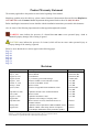
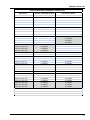
Revisions
Date
July, 1994
July 21, 1995
August 30, 1995
August 10,1998
August 7, 1999
October 27, 1999
January 7, 2000
April 14, 2000
Description
Preliminary Document
Release Manual
Second Release
Pg 1-51 battery power Name changes
Inclusion of MIO1 section and other revisions
Revisions to the MIO1 section
Minor revisions
Inclusion of Appendix B into Installation section
September 29, 2000
June 8, 2001
August 11, 2003
August 2004
September 2005
Updated to include 1140C/1140D information
Minor revisions
Updated to include the 1140G
Updated to reflect change of company name…
Minor cosmetic revisions; eliminated reference to
ScanBase software
Updated to reflect replacement of DPE with DPE+ sensor
Addition of DPE+ cable clamp, deletion of Chapter 4
(Local Display Menu Path), minor part number updates
January 2009
August 2010
By
K. MacLean, BIL
K. MacLean, BIL
T. DePass, BIL
P. Lee, BIL
P. Lee, BIL
P. Lee, BIL
D. Warren, BIL
P. Lee, BIL
P. Lee, BIL
P. Lee, BIL
P. Lee, BIL
—
K. Metzer
K. Metzer
K. Metzer
Barton, Scanner, ScanOp, ScanPC and ScanWin are trademarks or registered trademarks of Cameron International Corporation (“Cameron”).
Windows is a registered trademark of Microsoft Corporation in the U.S.A. and other countries.
Acrobat Reader is a registered trademark of Adobe Systems Incorporated.
iv
TABLE OF CONTENTS
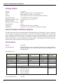
INTRODUCTION.............................................................................................................. 9 Overview of the Scanner 1140 ............................................................................................................................... 9 Scanners 1140T, 1140C, 1140L, and 1140G.................................................................................................... 10 Scanner Software .............................................................................................................................................. 10 CHAPTER 1: INSTALLATION .................................................................................... 11 Quick Start............................................................................................................................................................ 11 Operating/Storage Limitations ............................................................................................................................. 12 Unpacking ............................................................................................................................................................ 12 Mounting .............................................................................................................................................................. 12 Piping ................................................................................................................................................................... 12 Typical Installation of Scanner 1140T ............................................................................................................. 13 Typical Installation - Scanner 1140C/L Integral Communications .................................................................. 14 Typical Installation (with Remote Communications)....................................................................................... 15 Power Supply Connection ................................................................................................................................ 16 Power Supply ....................................................................................................................................................... 16 6-Volt Battery Power Supply, Division 1 Controller ....................................................................................... 16 Scanner 1140T (With Battery Cover Removed)........................................................................................... 17 12-Volt Battery Power Supply, Division 2 Controller ..................................................................................... 18 Scanner 1140C (Front View with Door Open) ............................................................................................. 18 Scanner 1140L (Front View with Door Open) ............................................................................................. 19 Scanner 1140G.............................................................................................................................................. 19 Solar Panel Installation and Connection........................................................................................................... 20 Flashing the Scanner ............................................................................................................................................ 21 Getting Ready to Flash ..................................................................................................................................... 21 Configuration Lock Switch .............................................................................................................................. 22 Start Flashing.................................................................................................................................................... 22 Flashing with ScanFlash ................................................................................................................................... 23 Flashing with WinsLoad (in Windows)............................................................................................................ 24 Installing WinsLoad...................................................................................................................................... 24 Using WinsLoad ........................................................................................................................................... 24 Flashing with ScanLoad (DOS)........................................................................................................................ 26 Installing ScanLoad Version 2.2................................................................................................................... 26 Using ScanLoad ............................................................................................................................................ 27 Troubleshooting the Flashing Procedure .......................................................................................................... 27 Startup Procedure ................................................................................................................................................. 28 Superbooting the Scanner ................................................................................................................................. 28 CHAPTER 2: MAIN BOARD AND WIRING ............................................................. 31 Main Circuit Board Diagram (Major Components) ............................................................................................. 31 Main Board Wiring Diagram ........................................................................................................................... 32 Field Termination................................................................................................................................................. 33 DIP Switch Summary........................................................................................................................................... 34 Memory Switches................................................................................................................................................. 35 v
Scanner 1140 Hardware User Manual
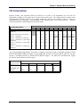
Switch Control DIP Switch (SW4) Summary .................................................................................................. 35 Superboot Switch.............................................................................................................................................. 37 Lithium Battery Switch..................................................................................................................................... 37 Analog Transmitter Inputs (Resources A09 – A10)............................................................................................. 38 Analog 4-20 mA Transmitter............................................................................................................................ 38 Analog 1-5 Vdc Transmitter (TxPwr) .............................................................................................................. 38 Analog 4-20 mA Output (Optional) ..................................................................................................................... 38 RTD Inputs (Resource A08)................................................................................................................................. 39 Frequency Pulse Inputs (Resource A07) .............................................................................................................. 40 Frequency Pulse Input DIP Switch (SW1) Summary....................................................................................... 40 Three-Wire Preamplified Turbine (Barton 818) 0-5V Output ...................................................................... 41 Two-Wire Preamplified Turbine (Barton 818) 0.5 - 5.5 mA Output............................................................ 42 Two-Wire Preamplified Turbine (Barton 818) 7-12 mA Output.................................................................. 43 Open Collector without “Bounce” ................................................................................................................ 44 Magnetic Pickup Coil.................................................................................................................................... 44 Dry Contact ................................................................................................................................................... 45 Pepperl & Fuchs Inductive Proximity Sensor............................................................................................... 45 Status Inputs and Outputs (Resources A03, A04, A05 and A06)......................................................................... 46 Console Serial Port (Resource A21) .................................................................................................................... 46 Auxiliary Serial Port (Resource A02) .................................................................................................................. 47 RS-232C ........................................................................................................................................................... 47 Auxiliary Serial Port Optional DIP Switch (SW3)............................................................................................... 48 MVX-II Wiring (RS-485 Communications)..................................................................................................... 49 CHAPTER 3: OPTIONAL BOARD AND WIRING ...................................................51 MIO1 Expansion Board........................................................................................................................................ 51 Specification......................................................................................................................................................... 51 General.............................................................................................................................................................. 51 Serial Port ......................................................................................................................................................... 51 Analog Output .................................................................................................................................................. 52 Status In/Status Out/Pulse Outputs................................................................................................................... 52 Pulse Inputs....................................................................................................................................................... 52 I/O Termination.................................................................................................................................................... 53 Configuration Switches ........................................................................................................................................ 55 Status Input/Output and Pulse Output Circuits................................................................................................. 55 Serial Port Switches.......................................................................................................................................... 55 Pulse Input Switches......................................................................................................................................... 55 Pulse Input Mode Select Switch Settings ......................................................................................................... 56 Analog Output Switch ...................................................................................................................................... 58 Circuit Board Wiring Diagrams ........................................................................................................................... 59 MIO1 Installation Procedure ................................................................................................................................ 62 CHAPTER 4: TROUBLESHOOTING..........................................................................63 Tools Required ..................................................................................................................................................... 63 Problems and Solutions ........................................................................................................................................ 63 Transmitter Voltage.............................................................................................................................................. 67 Main Battery Voltage ........................................................................................................................................... 68 vi
Table of Contents
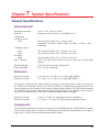
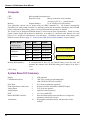
NVRAM Lithium Battery Voltage....................................................................................................................... 69 NVRAM Battery Change Procedure ................................................................................................................ 69 Returning the Scanner .......................................................................................................................................... 70 CHAPTER 5: DPE+ INSTALLATION......................................................................... 71 DPE+ Installation ................................................................................................................................................. 71 Replacing a DPE with a DPE+ Transducer ...................................................................................................... 71 Gasket Options.............................................................................................................................................. 72 Installing the Barrier Adapter (for Class I, Div. 1 installations only).............................................................. 74 CHAPTER 6: PRINCIPLES OF OPERATION .......................................................... 77 Application Software............................................................................................................................................ 77 Audit Trail ............................................................................................................................................................ 77 Central Processing Unit (CPU) ............................................................................................................................ 78 Memory ................................................................................................................................................................ 78 FPGA.................................................................................................................................................................... 78 Hardware Write Protection................................................................................................................................... 79 Clocks................................................................................................................................................................... 79 The Watchdog Timer ........................................................................................................................................... 79 Power Management.............................................................................................................................................. 79 Battery Power Options ......................................................................................................................................... 79 Transmitter Supplies ............................................................................................................................................ 80 Communications................................................................................................................................................... 80 Analog Inputs ....................................................................................................................................................... 80 RTD Inputs........................................................................................................................................................... 81 Pulse Inputs .......................................................................................................................................................... 81 Front Panel ........................................................................................................................................................... 82 Standard Display............................................................................................................................................... 82 Autoscroll ......................................................................................................................................................... 83 Barton DPE+ Cell................................................................................................................................................. 83 CHAPTER 7: SYSTEM SPECIFICATIONS ............................................................... 85 General Specifications.......................................................................................................................................... 85 Environmental .................................................................................................................................................. 85 Enclosure .......................................................................................................................................................... 85 Components ...................................................................................................................................................... 85 Computer .......................................................................................................................................................... 86 System Board I/O Summary............................................................................................................................. 86 Expansion Board Interface ............................................................................................................................... 87 Display.............................................................................................................................................................. 87 Keypad (optional) ............................................................................................................................................. 87 Communications Port ....................................................................................................................................... 87 Status In, Status Out, Pulse Out........................................................................................................................ 88 RTD .................................................................................................................................................................. 88 Analog Inputs ................................................................................................................................................... 88 Pulse Input Board (Optional)............................................................................................................................ 89 Analog Output Board (Optional) ...................................................................................................................... 89 vii
Scanner 1140 Hardware User Manual
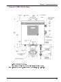
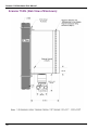
DPE+ Multi-Variable Transducer..................................................................................................................... 90 Transmitter Power Supply ................................................................................................................................ 91 Power Supply Options ...................................................................................................................................... 91 6 Volt Rechargeable Battery ......................................................................................................................... 92 Alkaline Battery ............................................................................................................................................ 92 DC Input........................................................................................................................................................ 92 12 Volt Rechargeable Battery ....................................................................................................................... 93 Software ............................................................................................................................................................... 93 Order Code ........................................................................................................................................................... 94 Outline Dimensions.............................................................................................................................................. 97 Scanner 1140T (Front View) ............................................................................................................................ 97 Scanner 1140T (Side Views) ............................................................................................................................ 98 Scanner 1140C (Front View)............................................................................................................................ 99 Scanner 1140C (Endcap Mount Side View)................................................................................................... 100 Scanner 1140C (Universal Mount Side View) ............................................................................................... 101 Scanner 1140G (Top View)............................................................................................................................ 102 Scanner 1140L (Front View) .......................................................................................................................... 103 Scanner 1140L (Side View of Enclosure)...................................................................................................... 103 Scanner 1140L (Side View of Enclosure) ...................................................................................................... 104 CHAPTER 8: PARTS LIST..........................................................................................105 Scanner 1140T.................................................................................................................................................... 105 Scanner 1140C ................................................................................................................................................... 109 APPENDIX A: INSTALLATION DRAWINGS.........................................................115 viii
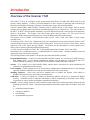
Introduction
Overview of the Scanner 1140
The Scanner® 1140 is an economical, single stream measurement Remote Terminal Unit (RTU) with flow and
pressure control capability. It offers a powerful alternative to chart recorders in gathering data for natural gas
production and includes a full range of operator selectable mass, energy and volume algorithms.
Cameron’s Barton DPE+ Multi-Variable Transducer (MVT) mounts directly to the Scanner 1140 to provide
accurate, low cost measurement for both static and differential pressures in a single device. The 1140 can also use
the MVX® or MVX®-II multi-variable transmitter to provide differential pressure, static pressure and temperature
inputs to the Scanner. The Scanner 1140 also accepts inputs from low-power (1-5 Vdc) and 4-20 mA
transmitters, RTDs, and pulse-producing devices such as the Barton and NuFlo turbine meters.
The Scanner 1140 is available in four different models (1140T, 1140C, 1140L and 1140G) to meet various
customer needs.
An intelligent 6Vdc, Class I, Div.1 Intrinsically Safe power management system ensures that the Scanner 1140T
consumes minimum power while collecting and processing data. It stores up to 60 days of flow history with an
audit trail of all events, alarms and user changes. The memory for this information is secured against power
failures with a separate replaceable lithium back-up battery.
A 12Vdc system is available for Class I, Div. 2 non-sparking applications (Scanner 1140C and 1140L).
Stored data can be downloaded on-site, or communicated to a central location. Standard communications and
status/pulse inputs can easily be expanded.
The following features in the Scanner 1140 provide convenient and flexible operation:
Programmable Memory - A full set of menu-selectable calculation options are stored in the FLASH memory in
each Scanner 1140. As new industry standards are adopted, new programs are easily loaded from a PC
without EPROM chip changes. (See the ScanLoad, WinsLoad or ScanFLASH utility software.)
Security - Five security levels and selectable display options ensure convenient use while maintaining full
protection of configuration and flow history.
Power Supplies - Choose from line power or various battery configurations with thermoelectric or solar charging
options to minimize installation costs and meet site and intrinsic safety requirements.
Sampling Frequency - Select ideal end device sampling rates to optimize the Scanner 1140’s ability to
simultaneously measure and control while conserving power.
Calibration - A variety of methods are available for linearizing different end devices to maintain the highest
accuracy. A detailed record of calibration information is stored automatically in the Scanner User Change
Log and can be used to monitor and diagnose transmitter performance.
Controls - Various control options are easily configured using simple menus with input/output selections for both
throttling and ON/OFF control. Four status input/outputs and an analog output make the Scanner 1140 ideal
for:
• proportional integral control
• emergency shutdown
• run switching
• programmable logic status
9
Scanner 1140 Hardware User Manual
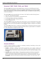
Scanners 1140T, 1140C, 1140L, and 1140G
The Scanner 1140T, often referred to as the standard Scanner 1140 unit, is a 6Vdc EFM rated for Class I,
Div.1 Intrinsically Safe applications. The device has no integral communications. It is housed in a fiberglassreinforced plastic enclosure. All Class I, Division 1 installations require an intrinsically safe barrier adapter
(Part No. 9A-30058901) between the Scanner and the DPE+ transducer. The adapter is not required for Class
I, Division 2 installations.
The Scanner 1140C has the same main board as the Scanner 1140T model but with the following features:
• Class I, Div. 2 non-sparking certification
• a larger enclosure that can accommodate a communication device
• 12 Vdc battery/charger control (up to 55 amp-hours)
• a power supply for powering a communication device
• an optional lightning arrestor
The Scanner 1140L has many of the features of the 1140C. However, it has a metal enclosure and its main
board is mounted on an aluminum plate instead of in an aluminum extrusion. It is limited to a 32-amp-hour
battery. The 1140L can be used with standard I/O with depluggable terminals or limited I/O with soldered
terminals.
The Scanner 1140G (shown below) is comprised of a standard Scanner 1140T main board, but has no integral
enclosure with a battery. It is designed to be installed in another enclosure or panel mounted. It is intended to
be a value-added product for integrators and E & C firms.
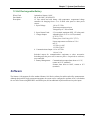
Scanner Software
A variety of software programs are available for configuring, monitoring, downloading, retrieving data,
reading and creating reports from collected data:
• ScanWin™ - ScanWin is a Windows™ based software program that is used to monitor, configure and
download Scanner Measurement RTU data on-site. Such data is displayed graphically and in tables.
Reports are printable from ScanWin. Monitor and download all firmware versions and configure version
4.x firmware.
• ScanPC® - ScanPC is a DOS / Windows™ 98 based software program for a PC that is used to monitor,
configure, and download Scanner Measurement RTU data on-site. Scanner files can be printed in a
universal report format or, outputted in either comma separated, or tab separated text formats. All report
files are readily imported into spreadsheet and database software programs. Used with version 2.x and
3.x firmware.
10
Chapter
1: Installation
CAUTION
POWER TO THE SCANNER 1140 MUST BE TURNED OFF PRIOR TO THE REMOVAL OF
ANY ELECTRONIC CIRCUIT BOARDS OR DAMAGE TO THE SCANNER MAY RESULT.
CIRCUIT BOARDS ARE SUBJECT TO DAMAGE IF EXPOSED TO STATIC ELECTRICITY.
HANDLING AND INSTALLING CIRCUIT BOARDS MUST BE PERFORMED IN AN
ENVIRONMENT FREE OF STATIC ELECTRICITY AND THE OPERATOR MUST BE
GROUNDED.
WHEN CIRCUIT BOARDS ARE REMOVED FROM THE SCANNER 1140, THEY MUST BE
PLACED IN PROTECTIVE CONDUCTIVE ENVELOPES.
Note:
Circuit boards returned to Cameron’s Measurement Systems Division factory for repair must be properly
packed for static protection or they will not be covered by the Cameron’s warranty.
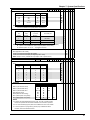
Quick Start
The following chart suggests a sequence for the installation of the Scanner 1140:
Step
Description
Reference Section
1
2
3
4
5
6
Unpack the Scanner
Mounting the flow computer
Connect to pipes
Connect power supply
Flash the Scanner (if changing installed firmware)
Startup
• Superboot
• Connect I/O
• Configure the EFM/RTU
Page 12
Page 12
Page 12
Page 16
Page 21
Page 28
Page 31
See Firmware/Software section of
manual
11
Scanner 1140 Hardware User Manual
Operating/Storage Limitations
Temperature:
Static Electricity:
The instrument is not to be subjected to ambient or operating temperatures beyond the range
listed in the specification section (Page 85).
The circuit boards are not to be subjected to any source of external static electricity.
Unpacking
Cameron’s Measurement Systems Division Scanners are carefully inspected during manufacturing and before
shipment. However, an inspection should be performed at the time of unpacking to detect any damage that may
have occurred during shipment. The following items should be included with each shipment:
• Scanner 1140 completely assembled
• Battery (optional)
• RTD (optional)
• Solar Panel (optional)
An IBM-compatible PC with ScanWin or ScanPC software is required to remotely configure and collect data
from the Scanner 1140.
Mounting
The standard bracket for all, with the exception of the 1140G, is a universal 2” pipe mount/wall bracket. These
models also offer an optional wall mount only bracket or a pipe ending bracket.
The 1140G is surface mounted by four user-supplied screws or by an optional DIN rail kit.
Refer to Page 97 - Outline Dimensions for size and location.
Piping
All piping connections are made in accordance with standard practices. For orifice meters, consult API chapter
14.3 Part 2 or AGA-3 Part 2 (1991) for additional information. For turbine meters, consult API chapter 5.3 or
AGA-7.
12
Chapter 1: Installation
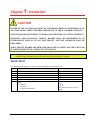
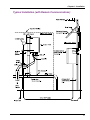
Typical Installation of Scanner 1140T
Class I, Division 1, Groups C & D Intrinsically safe or Class I, Division 2, Groups A, B, C & D non-sparking
13
Scanner 1140 Hardware User Manual
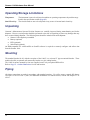
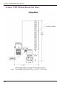
Typical Installation - Scanner 1140C/L Integral Communications
NuFlo
14
Chapter 1: Installation
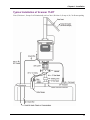
Typical Installation (with Remote Communications)
15
Scanner 1140 Hardware User Manual
Power Supply Connection
Conduit entry is provided on the right-hand side of the enclosure for the power supply/solar panel wires (refer to
Page 97 - Outline Dimensions for size and location of conduit entry.
WARNING
ALL METALLIC CONDUIT CONNECTORS MUST BE GROUNDED TO
THE INTERNAL GROUND WITH THE SHORTEST WIRE POSSIBLE.
Also, check Page 31 – (Main Board and Wiring) for additional wiring information.
Installation Drawings for information about installation in a Hazardous Location.
See Appendix A:
Power Supply
WARNING
THE BATTERY IS USER-CHANGEABLE. HOWEVER, IT MUST BE
REPLACED IN A NON-HAZARDOUS LOCATION.
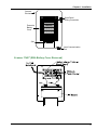
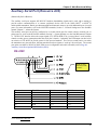
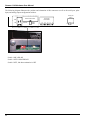
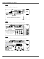
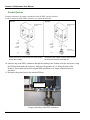
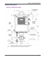
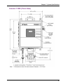
6-Volt Battery Power Supply, Division 1 Controller
(Intrinsically Safe when installed as per Appendix A: Installation Drawings 9A-1140-11002)
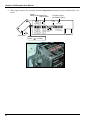
In a Scanner 1140T, the battery is located under a protective enclosure in the main body of the Scanner. To
access it, open the enclosure and loosen and remove the nuts off the bolts on the battery cover. Lift and slide
the cover out of the slot that the battery sits on.
The Scanner 1140C’s battery is accessed by loosening the Velcro strap securing it.
16
Chapter 1: Installation
Scanner
Enclosure
Solar Panel
Wiring Connection
Protective
Battery
Cover
Warning
Label
Slot
Local Communication
Port
Scanner 1140T (With Battery Cover Removed)
17
Scanner 1140 Hardware User Manual
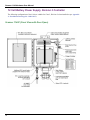
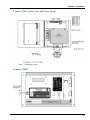
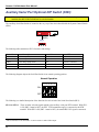
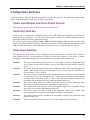
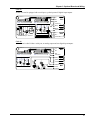
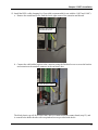
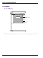
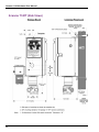
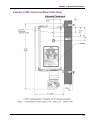
12-Volt Battery Power Supply, Division 2 Controller
The following configurations of the 1140 are suitable for Class I, Division 2 when installed as per Appendix
A: Installation Drawings 9A-1140-11012).
Scanner 1140C (Front View with Door Open)
18
Chapter 1: Installation
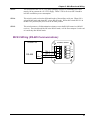
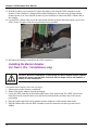
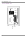
Scanner 1140L (Front View with Door Open)
Scanner 1140G
19
Scanner 1140 Hardware User Manual
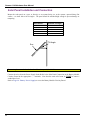
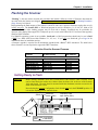
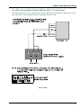
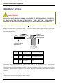
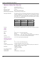
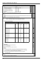
Solar Panel Installation and Connection
Mount the solar panel on a post, or directly to an equator-facing (or, at the equator, upward-facing) flat
surface – see chart below for tilt angles. The panel should be mounted high enough to prevent damage or
tampering.
Site Latitude
0°
5° - 20°
21° - 45°
46° - 65°
66° - 75°
Sun
Note:
Optimum Tilt Angle
10°
Latitude +5°
Latitude +10°
Latitude +15°
80°
Tilt Angle
Angles are marked on the bracket of the solar panel (0° - 90° tilt)
Connect the wires from the Power Supply Strain Relief to the Solar Panel Connection on the Battery Module
Circuitry Board in the appropriate +, - terminals. Note that the strain relief must be TIGHT to ensure a
weatherproof seal.
Refer to Page 16 - Battery Power Supply to access the Battery Module Circuitry Board.
20
Chapter 1: Installation
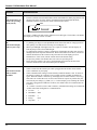
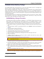
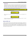
Flashing the Scanner
“Flashing” is the term used to describe the procedure that installs a different version of firmware other than the
one with which the Scanner was shipped. If changing the firmware is NOT necessary, the Startup Procedure
(Page 28) may be initiated.
Reprogramming the flash memory of the Scanner 1140 RTU with a new version of firmware requires the use of a
loading program. The ScanFLASH or WinsLoad program is used in a Windows 3.1, 95, 98, NT, 2000 or XP
environment. While either loading program may be used with a Scanner, ScanFlash may be preferable for
operators using laptops that support PC-COM ports up to 9 to work with USB to RS-232 converters that typically
install at higher locations.
If a Windows operating system is not available, ScanLoad is a DOS program that should only be run in DOS
(*NOT* in a DOS shell from within Windows 3.1, 95, etc.). If you must use ScanLoad, go to Page 26 for
information about its installation and use.
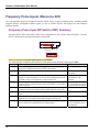
A firmware upgrade is required for all instruments upgraded with a Barton® DPE+ transducer. The table below
shows firmware versions required to support the DPE+ transducer.
Selection Chart for Scanner Firmware
If using this
firmware
Install this firmware version
(or later version)
Configure with
this software
NFlo version 4.x
NFlo 4.4.0F
ScanWin
NFlo version 3.x
NFlo 3.2.4F
ScanPC
NGas version 3.x
NGas 3.1.4F
ScanPC
NGas version 2.x
NGas 2.7.4F
ScanPC
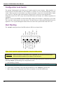
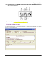
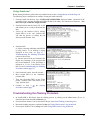
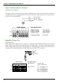
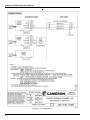
Getting Ready to Flash
Before starting, determine where the 8-switch bank of DIP switches, SW4 is located. SW4
can be found under the rubber plug, furthest from the hinge side, at the top of the Scanner
1140 main board. The main board is mounted inside the aluminum extrusion screwed to the
inside of the enclosure’s door.
Note also that the optional Configuration Lock Switch must be in the UNLOCK position. If
it is not, the flashing process cannot be done.
System
Switch (SW4) Serial Port
Switch (SW3)
Cover Plate
Frequency Pulse
Input Switch (SW1)
run
program
app
program
protect
superboot
64K
shutdown
100
485
on
on
on
RX term. off
diff mode 422
VTx2 12V off
DTR off
VTx2 DTR off
Display
contrast
Factory Test
Blk protect
FPGA boot
Flash protect
Mem Batt off
Restart norm
RAM 32K
run
Important:
Pulse Input
RS422 RS232
RS485
Resource AO7
See main diagram
Configuration Lock Switch
(slide
to UNLOCK)
21
Scanner 1140 Hardware User Manual
Configuration Lock Switch
The optional Configuration Lock Switch may be legally required in some locations. When installed, it is
located to the left of Switch SW4 (see above diagram). It consists of a cover plate that normally covers the
switch. When it needs to be accessed the screw nearer the Scanner’s front cover is loosened and the further
one is removed. The plate is then rotated until the locking switch is exposed as in the diagram above.
Sliding the switch to the LEFT (away from Switch SW4) allows the Scanner to be flashed, superbooted or
configured.
When it is moved to the RIGHT (towards Switch SW4), change to the Scanner’s configuration is prevented.
The cover plate is then rotated to cover the switch. The removed screw is then replaced and both screws are
tightened. A wire is passed through the heads of the screws and a seal is placed on the ends of the wire.
Start Flashing
64K
shutdown
Restart norm
RAM 32K
run
protect
Mem Batt off
program
Flash protect
app
FPGA boot
program
run
8
7
6
5
4
3
2
1
B.Blk protect
ON
factory test
superboot
The “normal” running positions of the DIP switches in SW4 are as shown below:
(Note: Switch 2 position is application dependent. It may be in either position.)
IMPORTANT: Before the Scanner 1140 firmware can be upgraded, you must have the ScanFLASH or
WinsLoad software loaded on your laptop in its own directory.
Whether you are intending to reprogram the Scanner with ScanFLASH, WinsLoad or ScanLoad, carry out the
following common steps and then go on to the pertinent section.
1. Start ScanWin or ScanPC.
2. Download all History, Configuration and Calibration data. (HIGHLY RECOMMENDED)
3. Exit from ScanWin or ScanPC.
4. “Power down” the Scanner 1140 by moving Switch SW4-1 to the “shutdown” position (ON).
5. Make certain that the Configuration Lock Switch, if installed, is in an UNLOCKED state.
22
Chapter 1: Installation
64K
shutdown
Restart norm
RAM 32K
run
protect
Mem Batt off
program
Flash protect
app
FPGA boot
program
run
8
7
6
5
4
3
2
1
B.Blk protect
ON
factory test
superboot
6. Set Switches SW4-5 to the “program” position (ON) and SW4-6 to the “FPGA boot” position (OFF).
SW4 should now look like this:
7. Continue below or go to Page 26 if you are using ScanLoad.
Flashing with ScanFlash
The ScanFlash utility is loaded on your ScanWin installation CD. Simply load the program into your computer
and follow the on-screen instructions.
23
Scanner 1140 Hardware User Manual
Flashing with WinsLoad (in Windows)
WinsLoad is used to flash the Scanner RTU using an MS Windows operating system.
If you must operate in a DOS environment, go to the section on Flashing with ScanLoad (DOS) – Page 26.
Installing WinsLoad
1. Obtain the WINSLOAD.ZIP file from Cameron’s Measurement Systems Division.
2. Open Windows Explorer and create a directory named WINSLOAD on the C: drive of your computer.
3. Unzip the contents of WINSLOAD.ZIP into C:\WINSLOAD. The ZIP contains five files including the
WINSLOAD application, two batch files and two shortcut (PIF) files.
Note: The shortcuts assume c:\winsload as the default directory – edit their properties if you copy
WINSLOAD and the two batch files elsewhere.
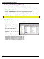
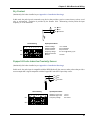
Using WinsLoad
The following steps is meant to serve as an example of using the WinsLoad utility:
1. Using Windows Explorer, drag the icon
of the binary firmware file onto
WINSLOAD1.PIF, WINSLD1.BAT or
WINSLOAD.EXE if you are using the
COM1 communication port on your PC.
The file may also be dragged and
dropped onto WINSLOAD2.PIF or
WINSLD2.BAT if your communication
port is COM2.
Alternatively, you can use the
Win95/98/NT command line.
For
Windows 3.1, you must use the Run
command in the Program Manager menu.
The binary firmware file name will be formatted as follows, depending on the version:
NGXXXXXX.B40 for all Ngas versions for the Scanner 1140
NFXXXXXX.B40 for all Nflo versions for the Scanner 1140
IGXXXXXX.B40 for all Igas versions for the Scanner 1140
OPXXXXX.B40 for all OPSat versions for the Scanner 1140
24
Chapter 1: Installation
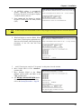
2. An MS-DOS window is automatically
opened. WinsLoad checks the validity of
the binary file and if it is all right, it displays
a window similar to this one.
3. Now, “power up” the Scanner by moving
the SW4-1 switch back to the “run” position
(OFF).
1. Note:
In this example, note that NGM411F.b40 is being dragged and dropped onto the Winsload1 Shortcut.
4. WinsLoad begins to erase the ROM. When
that is done, it then begins to upload the new
firmware to the Scanner while displaying the
percentage of the file that has been
transferred…
5. …until “Transmission completed.” Is reported. At this point, close the window.
6. Move Switch SW4-1 to the “shutdown”
position (ON).
7. Move Switches SW4-5 to the “Flash
protect” position (OFF) and SW4-6 to the
“app” position (ON).
8. It is HIGHLY RECOMMENDED that the
Scanner RTU be superbooted. To do this,
refer to the Startup Procedure – Page 28.
25
Scanner 1140 Hardware User Manual
Flashing with ScanLoad (DOS)
The use of ScanLoad should take place only if you are running in a DOS environment (not from within a
DOS “shell” when running Windows). Use WinsLoad if you are operating in an MS Windows operating
system.
The Getting Ready to Flash section (Page 21) should be carried out before using ScanLoad.
Installing ScanLoad Version 2.2
Note: This procedure must be done in a “Safe Area.”
ScanLoad requires the Scanner software as a binary file with the extension B40. It is recommended that
ScanLoad be installed onto the hard drive of the operator’s PC. Running ScanLoad from the hard drive
speeds up the downloading process.
To install ScanLoad from disk onto the hard drive perform the following sequence:
1. Turn ON the PC and wait for the C:\ prompt to appear on the screen. If the operator is currently using a
program, exit and return to C:\ prompt.
2. Make a ScanLoad directory by typing after the C:\ prompt:
md Scanload
3. Change the directory by typing after the C:\ prompt:
cd Scanload
4. The following prompt will appear:
C:\SCANLOAD>
5. Copy ScanLoad files EXE., TXT., and binary (*.B40) from the A drive to the hard drive by typing:
Copy a:*.*
(which will copy all the files that are on the disk, including the binary file) to the ScanLoad directory.
To copy ONLY the ScanLoad files, type the following after the C:\SCANLOAD> prompt:
Copy a: SCANLOAD.*
which will copy only the ScanLoad.EXE and TXT files from the disk.
The binary files must then be copied by typing:
Copy a: [binary name]
after the C:\SCANLOAD> prompt. (An example of a binary name is NGS260F.B40).
26
Chapter 1: Installation
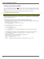
Using ScanLoad
Before starting ScanLoad, perform the steps outlined in the section, Getting Ready to Flash (Page 21).
The following steps is intended as an example of using the ScanLoad utility:
1. From the ScanLoad directory type: SCANLOAD NGM411F.B40, then press enter. (ScanLoad is the
executable file to start the program and NGM411F.B40 is the binary file with the new firmware). Note
that a newer file would have a different name.
2. ScanLoad checks that the binary file is OK
and informs you it is ready to download the
data.
3. “Power up” the Scanner 1140 by moving
Switch SW4-1 to the “run” position...this
will start the process of erasing the old
firmware in the Scanner 1140.
4. ScanLoad will:
a) display a message indicating which ROM
is being erased. If no message is being
displayed at this point, see page 27 –
Troubleshooting the Flashing Procedure
section of this section.
b) start the upload of the new firmware and
display the percentage of the program that
has been transmitted. If the percentage is
displayed as -1% or, if any Retries occur,
then see the Troubleshooting the Flashing
Procedure section (page 27).
5. Once ScanLoad is done, close the window.
6. Move Switch SW4-1 to the “shutdown”
position (ON).
7. Then, move Switches SW4-5 to the “Flash
protect” position (OFF) and SW4-6 to the
“app” position (ON).
8. Continue in Step 2 of the Startup
Procedure section (page 28).
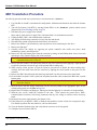
Troubleshooting the Flashing Procedure
•
•
•
•
In ScanFLASH or WinsLoad, abort the flashing process by clicking on the Close button (X) (or, in
ScanLoad, press both the Ctrl and Break keys).
Power down the Scanner 1140 as described in Step 4 of the Start Flashing section (Page 22).
Restart the loading program as explained in Step 1 of Using WinsLoad or Using ScanLoad.
Power up the Scanner 1140 as in Step 3 of either Using WinsLoad or Using ScanLoad.
27
Scanner 1140 Hardware User Manual
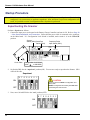
Startup Procedure
Note:
If the Scanner has been FLASHED or is NOT CONFIGURED, perform a Superboot. If it is already
configured, it is not necessary to perform a superboot. Also, note that if a previous configuration was
saved, it is possible to restore a configuration after a Superboot is performed.
Superbooting the Scanner
Perform a Superboot as follows:
1. Connect the input power (solar panel to the Battery Charge Controller) and turn it ON. Refer to Page 20
– Solar Panel Installation and Connection. Ensure that the power cable is connected to the connector
on the Main board. If a Configuration Lock Switch is installed, make certain it is in the UNLOCK
position.
System
Switch (SW4) Serial Port
Switch (SW3)
Cover Plate
Frequency Pulse
Input Switch (SW1)
run
program
app
program
protect
superboot
64K
shutdown
100
485
on
on
on
Factory Test
Blk protect
FPGA boot
Flash protect
Mem Batt off
Restart norm
RAM 32K
run
RX term. off
diff mode 422
VTx2 12V off
DTR off
VTx2 DTR off
Display
contrast
Pulse Input
RS422 RS232
RS485
Resource AO7
See main diagram
Configuration Lock Switch
(slide
to UNLOCK)
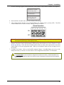
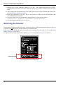
2. Set Switch SW4-3 to the “superboot” position (ON). You are now ready to superboot the Scanner. SW4
will look like this:
Superboot
8 7 6 5 4 3 2 1
CAUTION:
Superboot causes a LOSS of Configuration and
History data.
SAVE all Configuration and History data BEFORE
superbooting the Scanner RTU.
ON
OFF
3. Next, move Switch SW4-1 to the “run” position (OFF).
8 7 6 5 4 3 2 1
ON
OFF
28
Chapter 1: Installation
A series of messages appear on the local display as the Scanner 1140 performs its master reset sequence:
Superboot found,
Resetting unit
**REMINDER**
Setup unit for
non-superboot.
4. Start ScanWin or ScanPC and set the time and date at the prompt.
5. After setting the date and time, move Switch SW4-3 to the “Restart norm” position (OFF). The SW4
switches should now be in their “normal” running positions as follows:
Normal Operation
8 7 6 5 4 3 2 1
ON
OFF
Note:
Ensure that the Superboot Switch SW4-3 is shut OFF or configuration and history logs will be
lost if power fail occurs or if the system is reset.
6. If it is necessary to add new hardware to the Scanner RTU, disconnect or switch off input power to the
Scanner. Proceed to connect the transmitters, RTDs and any other end devices (refer to Chapter 2: Main
Board and Wiring). If the end devices include turbine meters or other pulse-output meters, ensure that
Switch SW4-2 is set to the appropriate mode. When you are finished, connect or turn on input power to
the Scanner.
7. Configure the Scanner. Refer to the ScanWin manual (Chapter 2: ScanWin Basics (Overview of the
Startup Procedure)) or Section 3.2 of the Scanner 1100 Configuration NGas/NFLo X.X.X manuals.
It is recommended that the new Scanner configuration be rebuilt in its entirety. Undesired problems may
result when a configuration file built in one firmware version is uploaded to another Scanner with a different
firmware version.
29
Scanner 1140 Hardware User Manual
8. Where legally required, the optionally installed Configuration Lock Switch may be enabled and the cover
sealed.
System
Switch (SW4) Serial Port
Switch (SW3)
Cover Plate
30
Frequency Pulse
Input Switch (SW1)
run
program
app
program
protect
superboot
64K
shutdown
100
485
on
on
on
Factory Test
Blk protect
FPGA boot
Flash protect
Mem Batt off
Restart norm
RAM 32K
run
RX term. off
diff mode 422
VTx2 12V off
DTR off
VTx2 DTR off
Display
contrast
Configuration Lock Switch
(slide
to LOCK)
Pulse Input
RS422 RS232
RS485
Resource AO7
See main diagram
Chapter
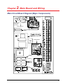
2: Main Board and Wiring
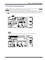
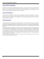
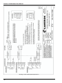
Main Circuit Board Diagram (Major Components)
Display Contrast
Frequency
RS 485/ RS422
or RS232C
Industry Canada
Configuration
Lock Switch
System Switches
Lithium Backup
Battery
-
+
Graphics
Analog Output
Program
Memory
4-20 INPUT
VRef
VA+
Gnd
VLCDb
AGnd
Vbe
Vbb
Vcc
VLCD+
VLCD-
PFInt
VTx2
VT1
Vpg
Vbi
RAM /NVRAM
Option Memory
Test
Points
TEST
128 K
RAM
Res
128 K
RAM
U20
U30
128 K
FLASH
Memory
31
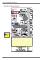
Scanner 1140 Hardware User Manual
Output
Input
Input
Input
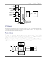
Main Board Wiring Diagram
Place expansion board decal here
Note:
Expansion
Board decal is
placed here.
32
Chapter 2: Main Board and Wiring
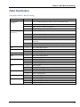
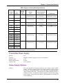
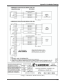
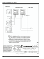
Field Termination
(6 Pin Input Connector – RS-232C setting)
Source
A21 (Remote
Console)
A02 Auxiliary Serial
(RS-232-C)
A03
A04
A05
A06
A07
A08
A09
A10
A11
Terminal #
1
Description
TxO – Gas chromatograph (secondary console) port transmit output
2
3
4
5
RxO – Gas chromatograph (secondary console) port receive input
DSRO – Remote console port DSR input
COMMON – Signal common
Tx1 – Auxiliary serial port transmit output
6
7
8
9
Rx1 – Auxiliary serial port receive input
RTS1 – Auxiliary serial port request to send (RTS) Output
CTS1 – Auxiliary serial port clear to send (CTS) input
RLSD1 (DCD) – Auxiliary serial port receive line signal detect (RLSD or
DCD) input
DTR1 – Auxiliary serial port data terminal ready (DTR) input
COMMON – Signal common
SIO1 – Status input/output #1
SIO2 – Status input/output #2
COMMON – Signal common
SIO3 – Status input/output #3
SIO4 – Status input/output #4
COMMON – Signal common
Pin + - Pulse input positive
Pin- - Pulse input negative
COMMON – Signal Common
RTDr – RTD R
RTD1 – RTD I1 (Signal Common)
RTD2 – RTD I2 (Signal Common)
TxPwr – Transmitter power output
Anin1 – Analog input #1
Anin2 – Analog input #2
COMMON – Signal common
Anout+ - Analog output positive
Anout- - Analog output negative
COMMON – Signal common
10
11
12
13
14
15
16
17
18
19
20
21
22
23
24
25
26
27
28
29
30
33
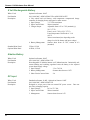
Scanner 1140 Hardware User Manual
Source
Terminal #
31
32
33
34
35
36
37
38
39
40
Description
EXP 01 - Expansion board terminal #1
EXP 02 - Expansion board terminal #2
EXP 03 - Expansion board terminal #3
EXP 04 - Expansion board terminal #4
EXP 05 - Expansion board terminal #5
EXP 06 - Expansion board terminal #6
EXP 07 - Expansion board terminal #7
EXP 08 - Expansion board terminal #8
EXP 09 - Expansion board terminal #9
EXP 10 - Expansion board terminal #10
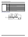
DIP Switch Summary
Serial Port
Switch (SW 3)
34
run
program
app
program
protect
su perboot
64K
shutdown
100 Ω
485
on
on
on
RX term . off
diff m ode 422
VTx2 12V off
DTR off
VTx2 DTR of f
Display
contrast
Factory Test
Blk protect
FPG A boot
Flash protect
M em Batt off
Restart norm
RAM 32K
run
System
Switch (SW 4)
Frequency Pulse
Input Switch (SW 1)
Pulse Input
RS422 RS232
RS485
Resou rce AO7
See m ain diagram
Chapter 2: Main Board and Wiring
Memory Switches
Switch Control DIP Switch (SW4) Summary
The Switch SW4 located at the top left of the main board controls several important functions:
System ( SW4 )
8 7 6 5 4 3 2 1
ON
The following table summarizes SW4’s functions and settings:
Switch #
SW4-1
SW4-2
SW4-3
SW4-4
SW4-5
SW4-6
SW4-7
SW4-8
Description
System shutdown
RAM size select
(Firmware 4.3 and higher)
Restart type select
Battery backup switch
FLASH memory program
enable
Boot block FPGA version
select
Boot block program enable
System mode select
ON
Shutdown
64K RAM
(96K RAM)
Superboot
(Enabled)
Enabled
OFF
(Running)
32K RAM
(64K RAM)
(Normal)
Disabled
(Disabled)
(Application Version)
Boot version
Enabled
(Normal Mode)
(Disabled)
Debug Mode
Settings in parentheses ( ) are for the normal operating mode.
The following diagram illustrates SW4’s settings for normal operation:
Normal Operation
8 7 6 5 4 3 2 1
ON
OFF
35
Scanner 1140 Hardware User Manual
Below is a detailed description of the functions of each switch on the System Control Switch SW4:
SW4-1:
This switch performs a properly supervised system shutdown. Rather than simply
driving the system RESET line, SW4-1 generates a power fail interrupt to the CPU, and
after a 10 ms delay (for the power fail code to run) shuts the power off to the entire
system board. The current draw of the system board is reduced to below 50 mA when
shut down.
Temporarily placing Switch SW4-1 in the ON position causes a Power On Restart. A
Power On Restart interrupts the flow calculations but does not affect the configuration or
historical flow data if the NVRAM lithium backup battery (see Page 37) is enabled.
Power On resets are logged in the event log. The display will show:
Power on Restart
36
SW4-2:
This switch determines how the system’s base 128 Kbytes (or 256 Kbytes) of memory is
partitioned. When ON, 64 Kbytes of RAM and 64 Kbytes of NVRAM are provided.
When OFF, 32 Kbytes of RAM and 96 Kbytes of NVRAM are provided. Alternatively,
the 256 Kbytes is partitioned as follows; when ON 64 Kbytes of RAM are provided, and
192 Kbytes of NVRAM; when OFF, 32 Kbytes of RAM is provided and 224 Kbytes of
NVRAM are provided.
Note that the RAM values change to 96K (ON position) and 64K (OFF position) with
Firmware 4.3x and higher.
SW4-3:
This switch determines which type of system startup is performed. When ON, a
“Superboot” occurs. When the Scanner 1140 is turned ON a superboot initializes all of
the non-volatile memory. A Superboot is required for any changes made to any of the
switch settings to become effective. When OFF, a normal restart occurs.
SW4-4:
This switch enables and disables the lithium backup battery and should be left in the ON
position when the Scanner is in operation. However, if the Scanner is stored for any
period of time (a week or more), the switch should be shut OFF (refer to Page 37 Lithium Battery Switch).
SW4-5:
This switch enables programming of the FLASH memory array by connecting the +12V
programming voltage to the VPP pin of each of the FLASH memory devices. Unless a
new application code is being downloaded to the system, the switch should be left in the
OFF position.
SW4-6:
This switch determines the location from which the field programmable gate array
(FPGA) is loaded. When SW4-6 is OFF, the array is loaded from the FLASH memory's
protected "boot" block. The boot block is a special 8-Kbyte area of the FLASH memory
array that can be independently erased and reprogrammed. When SW4-6 is ON, the
array is loaded from the FLASH memory application area. This is the normal position of
this switch.
SW4-7:
This switch enables/disables programming of the FLASH memory “boot” block. This
function can only be performed at the factory, so SW4-7 should be left in the OFF
(disabled) position at all times.
Chapter 2: Main Board and Wiring
SW4-8
This switch is to select either normal operation (ON) or a specialized factory test mode
(OFF). SW4-8 should therefore be left in the ON (normal) position at all times.
Superboot Switch
A “Superboot” erases all configuration and flow data when power is turned ON. A superboot is required
when first commissioning the unit (after turning the NVRAM battery switch ON). A superboot is not
required if the Scanner 1140 is already configured. However, it is possible to restore a configuration if a
superboot is performed.
To perform a superboot:
1. On the System Control DIP switch SW4, place Switch SW4-1 in the normal operating position (OFF),
and set Switch SW4-3 to the ON position.
2. Turn Switch SW4-1 ON and then OFF, or cycle the power OFF and then ON. The Scanner will begin its
system reset. The display will show:
Superboot Found
Resetting Unit
**Reminder**
Setup Unit for
non-Superboot
3. Set SW4-3 to the OFF position.
Lithium Battery Switch
Switch SW4-4 on the System Control Switch (SW4) enables backup power to the NVRAM. The Scanner
1140 is shipped with the battery switch in the OFF position. The switch must be set ON before configuring
the flow computer. Loss of input power while Switch SW4-4 is OFF will scramble the entire contents of the
NVRAM (including all configuration and flow data), and a “Superboot” will be necessary.
If the computer is stored without power for extended periods (i.e. a week or more), the NVRAM battery
switch is set OFF to avoid draining the lithium battery. The reset switch is set ON as follows:
Storage
8 7 6 5 4 3 2 1
ON
OFF
Note:
Storage of the Scanner with the lithium battery switch in the ON position will drain the lithium
battery. If the lithium battery is drained, it must be replaced.
37
Scanner 1140 Hardware User Manual
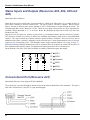
Analog Transmitter Inputs (Resources A09 – A10)
Analog 4-20 mA Transmitter
(Intrinsically Safe only with barrier)
Use of conventional 4-20 mA transmitters requires the addition of precision load resistors on each analog
channel. Power for the current loop is normally drawn from an external source.
4-20 mA
+
25
ANin1
26
ANin2
27
Common
Analog 1-5 Vdc Transmitter (TxPwr)
(Intrinsically Safe)
The use of conventional 1-5 Vdc transmitters requires no load resistors. Power for the circuit is normally
obtained from the Scanner’s internal power supply, but may also be drawn from an external source. The
configuration is Intrinsically Safe when used with approved transmitter. Refer to Appendix A: Installation
Drawings.
1-5 Vdc
24
Out
+
25
TxPwr
Anin1
26
Anin2
27
Common
Analog 4-20 mA Output (Optional)
An optional single 4-20 mA analog output is available. To determine if the analog output is installed, use the
configuration software (ScanWin or ScanPC) to examine the hardware section. Alternatively, look at the analog
output check box on the bottom of the wiring decal affixed to the extrusion. It is also possible to determine if this
option is installed by inspecting the board or checking the ASM number with Cameron’s Measurement Systems
Division factory.
If it is not installed, an analog output can be obtained via the addition of an expansion board.
28
+
ANout+
ANoutCommon
Output load
38
A11
Chapter 2: Main Board and Wiring
RTD Inputs (Resource A08)
(Intrinsically Safe when installed per Appendix A: Installation Drawings)
Resource A08 is connected to 100Ω 3-wire platinum RTD as shown. The RTD characteristic curve is softwareselectable for temperature coefficients of either 0.003902 or 0.00385 (Ω/Ω/°C) or by performing a loop
calibration at three or more points (refer to the NGas/NFLo manuals (Section 2 - Analog and RTD Calibration) or
to the ScanWin manual (Chapter 3 – Calibrate/Verify Devices)).
21
RTDr
22
RTD1
23
RTD2
Platinum 2-wire RTDs can be used by jumping the lead-line compensation terminals together.
CAUTION:
If a 4-wire RTD is used, apply heat shrink or electrical tape to the unused wire to prevent an electrical short.
39
Scanner 1140 Hardware User Manual
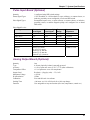
Frequency Pulse Inputs (Resource A07)
The 1140 frequency inputs are designed to interface with a variety of pulse producing sources, including turbine
magnetic pickups, preamplified turbine signals, as well as contact closures and Pepperl & Fuchs inductive
proximity sensors.
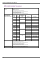
Frequency Pulse Input DIP Switch (SW1) Summary
An eight position DIP switch (SW1) allows user configuration of the desired electrical interface. Switch 1
(SW1) is located at the top right of the main circuit board:
Pulse in
ON
(SW1)
8 7 6 5 4 3 2 1
If SW1 is not present, the pulse input option is not installed.
The following table summarizes the function of each switch on the Frequency Input Switch (SW1):
Switch #
1
2
3
4
5
6
7
8
40
ON
Connects +8 Vdc transmitter power supply (VTX2) to the PIN+ terminal
(#18) for preamplified pulse and proximity sensor modes
5.68V comparator threshold
Connects a 620Ω load resistor across the high level signal input to
support 7-12 mA transmitters; e.g. used to convert the Pepperl & Fuchs
proximity sensor current signal to a voltage for detection
Debouncing - input sampling at 32 Hz allowing signals up to 16 Hz to be
properly detected (higher frequency pulses generated by contact bounce
will be rejected)
Connects the output of the flow computer’s pulse preamplifier to signal
comparator for low level signals such as turbine magnetic pickup coils
Connects the PIN- terminal (#19) to the signal comparator for high level
inputs
Connects PIN+ terminal (#18) to the preamplifier’s transformer coupled
input for low level signals such as turbine magnetic pickup coils
Forces the +5V to +12V charge pumping circuit to be permanently
active; must be ON to generate the +8V VTX2 supply
OFF
N/A
1.235V comparator
threshold
Regular for voltage type
preamplifiers or dry
contacts
Normal - input is sampled
at 32 kHz allowing signals
up to 16 kHz to be detected
N/A
N/A
Transformer not connected
Should be left OFF if not
in use to minimize power
consumption
Chapter 2: Main Board and Wiring
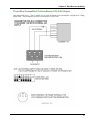
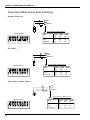
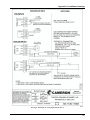
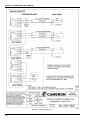
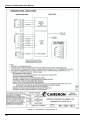
Three-Wire Preamplified Turbine (Barton 818) 0-5V Output
(Non-Intrinsically Safe) - This is suitable for use with the Barton 818A preamplifier configured for voltage
output mode. This preamplifier provides a transmission of up to 30 m.
41
Scanner 1140 Hardware User Manual
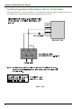
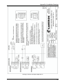
Two-Wire Preamplified Turbine (Barton 818) 0.5 - 5.5 mA Output
(Non-Intrinsically Safe) - This is suitable for use with the Barton 818A preamplifier configured for currentloop output mode. This preamplifier provides a transmission of up to 5 Km.
42
Chapter 2: Main Board and Wiring
Two-Wire Preamplified Turbine (Barton 818) 7-12 mA Output
(Non-Intrinsically Safe) - This is suitable for use with the Barton 818A preamplifier configured for currentloop output mode. This preamplifier provides a transmission of up to 5 Km.
43
Scanner 1140 Hardware User Manual
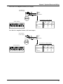
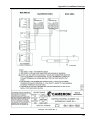
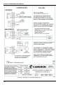
Open Collector without “Bounce”
(Intrinsically Safe w/Barriers)
This mode provides a generic pulse input, which is compatible with a variety of pulsers and other end devices.
A suitable end device is one that provides a bounce-free solid state output stage, such as an open collector
transistor or open-drain MOSFET.
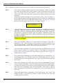
Magnetic Pickup Coil
(Intrinsically Safe)
In this mode, the pulse input is directly connected to a standard variable-reluctance pickup coil and is used on
Barton 7400 series gas turbine meters and other meters of similar design. The input is transformer-coupled to
ensure common-mode noise rejection, and incorporates a variable gain stage to increase the sensitivity to low
frequency and low amplitude signals. Shielded cable (such as Belden 9322) is required.
ON
OFF
44
7
6
5
4
3
Pin +
19
20
Pin Common
Input Specifications
Switch Setting
8
18
2
1
Input Impedance:
10KΩ @ 1 KHz
(signal < 1000 mV p-p)
Input Sensitivity:
20 mV p-p @ 20 Hz.
20 mV p-p @ 100 Hz.
200 mV p-p @ 1000 Hz.
400 mV p-p @ 2000 Hz.
1000 mV p-p @ 5000 Hz.
Chapter 2: Main Board and Wiring
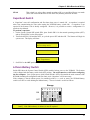
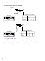
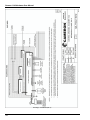
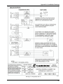
Dry Contact
(Intrinsically Safe when installed as per Appendix A: Installation Drawings)
In this mode, the pulse input is connected to any device that provides a passive contact closure, such as a reed
relay or microswitch. Excitation is provided by the Scanner 1140. Debouncing circuitry limits the input
frequency to 15 Hz maximum.
Pin +
Pin -
18
19
20
Input Specifications
Switch Setting
8
7
6
5
4
3
Common
2
Offstate Voltage:
Offstate Leakage:
Onstate Current:
Frequency Range:
Maximum Contact
Bounce:
1
ON
OFF
+5 V nominal
25 μA maximum
50 μA nominal
0 to 15 Hz @ 50 duty cycle
15 msec.
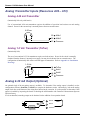
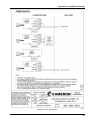
Pepperl & Fuchs Inductive Proximity Sensor
(Intrinsically Safe when installed as per Appendix A: Installation Drawings)
In this mode, the pulse input is compatible with the BSR (Rockwell) slot sensor or other pulsers that provide a
current output that is signal compatible with the Pepperl & Fuchs #SJ2-N proximity sensor.
+
ON
7
6
5
4
3
Pin +
19
20
Pin Common
Input Specifications
Switch Setting
8
18
2
1
Maximum Low Level:
Minimum High Level:
Frequency Range:
1.0 mA
3.0 mA
0 to 5 KHz
OFF
45
Scanner 1140 Hardware User Manual
Status Inputs and Outputs (Resources A03, A04, A05 and
A06)
(Intrinsically Safe w/Barriers)
+
Output
Input
Input
Input
Status inputs are used to read the state of an external device, which can be either passive (e.g. contact closures) or
active where excitation is from an external source. The type of input is selected by software. When a passive
input is selected, an internal power source attempts to drive a 50-microampere current through the circuit. The
voltage through this circuit is limited to 3.2 Vdc. When an active input is selected, the user is provided software
selectable voltage thresholds of 2, 7 or 10 Volts. Below the threshold, the input will be false (off); above the
threshold, true (on).
Outputs are used for status (e.g. alarms) or pulse train (e.g. accumulated volume) and are selected by software.
The circuits are suitable for a variety of end devices including small inductive loads such as electromechanical
counters. The output circuits have limited protection against inductive “kickback” from such devices, but an
additional safety factor is gained by strapping a diode across the load. Current requirements in excess of 100 mA
require the use of interposing relays. The transmitter power supply terminals marked “Vtx” (refer to Page 32 Main Board Wiring Diagram) should not be used for excitation since the computer can switch OFF the power to
these terminals under software control. Excitation should instead be drawn from an external source.
On the Scanner 1140, SIO1, SIO2, SIO3 and SIO4 are capable of both status inputs and outputs.
+
12
SIO1
13
SIO2
14
Common
15
SIO3
16
SIO4
17
Common
Console Serial Port (Resource A21)
(Intrinsically Safe only when using an HT-88A Handheld)
The console port is accessed through the bottom socket on the main terminal block of the instrument. This port is
used with a console device, such a PC or a gas chromatograph.
46
Chapter 2: Main Board and Wiring
Auxiliary Serial Port (Resource A02)
(Intrinsically Safe w/Barriers)
The auxiliary serial port supports full RS-232C hardware handshaking signals and is used with a modem to
provide remote communication or to connect peripheral devices such as the NuFlo MVX® or MVX®-II
multivariable transmitters, Daniel gas chromatographs and ultrasonic meters to provide additional inputs via serial
ports. (For more information, refer to the NGas/NFlo manuals, Section 3 - Network Settings or to the ScanWin
manual, Chapter 5 – About the System).
The auxiliary serial port can also be configured as a second console port for remote console, network port, or
printer port etc. (refer to the NGas/NFlo manuals, Section 3 - System Settings or to the ScanWin manual, Chapter
5). The RS-232C interface allows the output signals (TX, RTS & DTR) to be “powered-down” under software
control to reduce power consumption when the serial port is inactive. Optionally, the DTR output can also be left
on exclusive of TX & RTS to provide power for line powered modems. The receivers remain active even when
the transmitters are powered-down, allowing transitions on these inputs to “wake-up” the serial port. The second
port option can either be RS-422 or R485, both are user configurable and switch selectable (refer to Page 48 Auxiliary Serial Port Optional DIP Switch (SW3)).
RS-232C
“RLSD” is more
commonly known
as “DCD.”
Terminal
5
6
7
8
9
10
11
RS-232C
Tx
Rx
RTS
CTS
DCD
DTR
Signal Ground
RS-422
Rx+
RxTx+
TxN.C.*
N.C.*
Signal Ground
RS-485
Sig+
SigN.C.*
N.C.*
N.C.*
N.C.*
Signal Ground
* N.C. means Not Connected.
47
Scanner 1140 Hardware User Manual
Auxiliary Serial Port Optional DIP Switch (SW3)
Note:
If Switch (SW3) is not present, the default is RS-232. If SW3 Serial DIP Switch option has been
installed, then RS-232/RS-422/RS-485 is switch selectable.
The Auxiliary Serial Port Switch is located on the very top of the circuit board beside the System Control Switch
(SW4):
(SW3)
Serial
ON
5 4 3 2 1
The following table summarizes SW3’s functions and settings:
Switch #
SW3-1
SW3-2
SW3-3
SW3-4
SW3-5
Description
VTX2 output to DTR
RS-232 output DTR
+12V charge pump switch 1
Differential mode select
Receiver termination select
ON
Selected
Selected
ON
RS-485 mode
100Ω termination
OFF
Deselected
Deselected
Software Controlled
RS-422 mode
No termination
The following diagram depicts the Serial Port Switch in its normal operating position:
Normal Operation
5 4 3 2 1
ON
OFF
The following is a detailed description of the functions for each switch of the Serial Port Switch (SW3):
SW3-1 & SW3-2: These switches select the signal applied to the auxiliary serial port DTE terminal. With SW31 ON (SW3-2 must be OFF), the 8.0V VTX2 transmitter supply is connected to the DTR
terminal. With SW3-2 ON (SW3-1 must be OFF), the normal RS-232C signal is connected.
1
This switch must be ON when SW3-1 is ON to ensure a stable VTX2 output.
48
Chapter 2: Main Board and Wiring
SW3-3:
This switch forces the +5V to +12V charge pumping circuit to be permanently active and
must be ON to generate the +8V VTX2 supply. When VTX2 is not in use SW3 should be
left OFF to minimize power consumption.
SW3-4:
This switch is used to select the differential mode of the auxiliary serial port. When ON, it
selects RS-485 mode and when OFF, selects RS-422 mode. When slide switch SW3-2 is in
the RS-232C position (ON), SW3-4 can be in either position.
SW3-5:
This switch connects a 120Ω termination resistance across the RS-485 transceiver (RS-422
receiver). The switch should be ON in the RS-422 mode, or if the flow computer is at the end
of a multi-drop line RS-485 mode.
MVX-II Wiring (RS-485 Communications)
TERMINAL BOARD
DGnd
POWER
RS-485
+
-
TB1:3
TB1:4
TB1:5
Shield
+
I-
-
RTD-
RS-485
SCANNER 1140
A
RTD+
B
I+
TB1
TB2
49
Scanner 1140 Hardware User Manual
50
Chapter
3: Optional Board and Wiring
MIO1 Expansion Board
The Scanner 1140 MIO1 expansion board is a multi-purpose I/O expansion card that provides an RS-232C/RS485/RS-422 serial port, a 1-5V/4-20 mA analog output and a multi-interface pulse input. Each of the interface
types for these circuits is switch selectable. In addition, the board provides a second RS-232C (only) serial port
and four ports that can be individually (software) configured for operation as a status input, status output, or pulse
output. Because of terminal limitations (ten total), the board does not allow all of the I/O circuitry to be installed
at once.
The MIO1 installs in the Scanner 1140’s expansion slot, and is shipped with a ten-point terminal block plug to
enable field-wiring termination. The configuration switches for the serial port, analog output, and pulse input are
located at the bottom of the card.
Specification
General
Operating Temperature
Classification
Relative Humidity
40°C to +60°C
CSA certified for Class I, Div. 1, Groups C & D
10% to 95% non-condensing
Serial Port
Quantity
Port 1 Electrical Interface
Useable 3 Baud Rates
Parity
Stop bits
2
1 (optional)
RS-232C c/w TX, RX, RTS, and CTS 2 or RS-422RS-422, or RS-485 (user
configurable)
110, 150, 300, 600, 1200, 2400, and 4800 baud, software selectable
Even, odd, or none, software selectable
1 or 2, software selectable
CTS is not provided on some assembly versions due to terminal allocation limitations.
3
Higher baud rates may be selected, however, received characters may be lost due to interrupt processing limitations,
especially in packet oriented protocols.
51
Scanner 1140 Hardware User Manual
Analog Output
Quantity
Isolation
Type
Accuracy
Temperature Effect
Minimum Operating Voltage
Maximum Voltage
Minimum load (1-5V mode)
D/A Resolution
Calibration
Settling Time
1 (optional)
Optically isolated to 500 VAC, externally powered
Switch selectable as either 1-5V or 4-20 mA
±0.1% of FS max. error @ 25°C (after software calibration)
±1% of FS max. error over temperature
6.5 Vdc (4-20 mA), 9.5 Vdc (1-5V)
±40 Vdc
10KΩ
12 bits
Zero and Full-scale software calibration
<100 msec. to ±0.1% of span for a full-scale step change
Status In/Status Out/Pulse Outputs
The MIO1 board provides four (maximum) digital I/O channels that can be individually ‘software’ configured
as status inputs, status outputs or pulse outputs. Each of the four channels is identical, and is implemented
using a comparator for detecting the state of an (status) input, and an n-channel MOSFET to provide an open
drain status output driver. Pulse outputs are provided by simply driving the status output on and off at the
required pulse output rate in an interrupt driven software routine. The channels on the MIO1 board are
identical to those on the main board. Refer to pages 46 and 88.
Pulse Inputs
Quantity
Pulse Signal Types
1 (optional)
Pre-amplified square wave, open collector, contact closures, Pepperl & Fuchs
inductive proximity sensor or turbine magnetic pickup coil configured via on
board DIP switch.
Pulse Signal Levels
Pulse Type
Square Wave
Square Wave
Open Collector
Contact Closure
Inductive Proximity
Sensor
Maximum Low Level
Signal
4.5V
1.0V
Minimum High Level
Signal
7.5V
1.5V
2 KΩ
2 KΩ
1 mA
200 KΩ
200 KΩ
3 mA
Minimum Signal Levels
Magnetic Pickup Coil 20
mV p-p @ 20
20
mV p-p @ 100
200
mV p-p @ 1000
400
mV p-p @ 2000
1000
mV p-p @ 5000
Over-voltage Protection
52
±40 VDC
Frequency
Range
0 - 10 kHz.
0 - 10 kHz.
0 - 10 kHz.
0 - 10 Hz.
0 - 5 kHz.
Input
Impedance
> 10 KΩ
> 10 KΩ
N.A.
N.A.
N.A.
Impedance
Hz.
Hz.
Hz.
Hz.
Hz.
10 KΩ @1 kHz.
Chapter 3: Optional Board and Wiring
I/O Termination
Because Scanner 1140 expansion boards are limited to 10 points of I/O termination, not all of the I/O
functionality available on the board can be accessed at the same time. The design therefore provides some
interconnection flexibility between the terminal connections and the I/O circuitry so that a variety of
configurations may be supported. The part number of the expansion board is 9A-1140-0210B-code. The table
below documents the valid combinations for RS-232 mode:
Terminals
31
32
Assembly Description
Code 05 - 1 pulse input + 1 analog out +
2 status I/O
Code 06 – pulse input + 4 status I/O
Code 10 - 1 serial port
Code 11 - 1 serial port + 4 status I/O
Code 12 - 1 serial port + 1 pulse input +
1 analog out
Code 13 - 1 serial port + 1 pulse input +
2 status I/O
Code 14 - 1 serial port + 1 analog out +
2 status I/O
33
34
35
36
37
38
39
PIN+
PIN-
GND
SIO1
SIO2
GND
ANO+ VOUT
ANO-
PIN+
RX
RX
RX
PINRTS
RTS
RTS
GND
CTS
GND
GND
SIO1
GND
SIO1
PIN+
SIO2
GND
SIO2
PIN-
GND
GND
GND
GND
SIO3
TX
TX
TX
SIO3 SIO4
ANO+ VOUT
GND
ANO-
TX
RX
RTS
GND
SIO1
SIO2
GND
PIN+
GND
TX
RX
RTS
GND
SIO1
SIO2
GND
ANO+ VOUT
SIO4
PIN-
40
ANO-
Any of the assemblies that include a serial port c/w signal Cts may also provide a switchable interface to afford
RS-232C/RS-485/RS-422RS-422 support. Any assembly that provides a serial port without signal Cts may also
provide a switchable interface to afford RS-232C/RS-485 support. The table below documents the signals
provided for each of the three interface types.
Interface
Terminals #
Type
31
32
33
34
35
RS-232-C
RS-422RS-422
RS-485
TX
Rx+
Data+
RX
RXData-
RTS
Tx+
N.A.
CTS
TxN.A.
GND
GND
GND
53
Scanner 1140 Hardware User Manual
The following diagram illustrates the position and orientation of this connector as well as the serial port, pulse
input, and analog output configuration switches.
Analog Out
Select
Serial Interface Select
OFF
ON
422/485
1
2
RS232C
RS422
RS485
Termination
Switch 1 ON is RS-485
Switch 1 OFF is RS-422RS-422
Switch 2 OFF, 100 ohm termination is OFF
54
Pulse Input
Mode Select
1 2
3 4
5 6
7
8
Vout
Iout
Chapter 3: Optional Board and Wiring
Configuration Switches
As illustrated above, the board provides configuration switches for serial port, the pulse input and the analog
output. A brief description of each of the switches is given below:
Status Input/Output and Pulse Output Circuits
All settings are software selected. Hence, there are no switches to set.
Serial Port Switches
The serial port’s configuration is controlled by both a 2-bit ‘DIP’ switch and a multi-pole slide switch (see
dotted area or above diagram). The slide switch selects between an RS-232-c interface (left-hand position)
and an RS-422/RS-485 interface (right hand position).
DIP switch #1 selects between RS-422 (open - OFF) and RS-485 (closed - ON) interfaces (the slide switch
must be in the RS-422/RS-485 position). DIP switch #2 connects a 100Ω termination and should be closed
(ON) for an RS-422 interface or if the MIO1 board is the last device on a multi-drop RS-485 network.
Pulse Input Switches
The eight-position ‘DIP’ switch is used to configure the pulse input circuitry to interface with a variety of
pulse-producing devices. A description of the function of each of the switches is given below; a detailed
description of the switch settings required for each interface is given in the Pulse Input section.
Switch #1:
Switch #2:
Switch #3:
Switch #4:
Switch #5:
Switch #6:
Switch #7:
Switch #8:
This switch connects the system board’s Vtx2 (+8.0V) supply to the Pin+ terminal and can be
used to power external pulse producer’s such as the Pepperl & Fuchs inductive proximity
sensor.
This switch determines the threshold of the comparator section when measuring high level
signals. When closed, the high level threshold (~5.8V) is selected, and when open the lowlevel threshold (~1.2V) is selected.
This switch connects a 620Ω load resistor into the high level circuit and is used to terminate
current mode devices such as the Barton 818 (7-12 mA mode) preamplifier, and the Pepperl
& Fuchs inductive proximity sensor (1-3 mA). This termination produces voltage levels
compatible with the high and low level voltage thresholds respectively.
This switch enables (closed) or disables (open) the interface circuit’s debouncing logic.
Debouncing is typically enabled when interfacing to contact closures.
This switch connects the interface circuits pre-amplifier output to the comparator section
input, and is closed when using magnetic pickup coils.
This switch connects the Pin- terminal to the comparator section and is closed when
measuring high level signals such as the output of a Barton 818 preamplifier.
This switch connects the Pin+ terminal to the pre-amplifier section and is closed when using
magnetic pickup coils.
This switch connects the system board’s Vtx1 (+10V) supply to the Pin+ terminal.
55
Scanner 1140 Hardware User Manual
Pulse Input Mode Select Switch Settings
Magnetic Pickup Coil
Pin +
Pin Common
Pin Numbers on MIO1 Boards
ON
Switch Setting
1
2
3
4
5
6
Pin
7
8
Code
05
32
33
34
Pin +
Pin Common
Code
12
35
36
37
Code
13
38
39
40
Dry Contact
Pin +
Pin Common
Pin Numbers on MIO1 Boards
System Setting
ON
Pin
1
2
3
4
5
6
7
8
Code
05
32
33
34
Pin +
Pin Common
Code
12
35
36
37
Code
13
38
39
40
Open Collector without “Bounce”
Pin +
Pin Common
Pin Num bers on MIO1 Boards
ON
Switch Setting
56
1
2
3
4
5
6
Pin
7
8
Pin +
Pin Com m on
Code
05
32
33
34
Code
12
35
36
37
Code
13
38
39
40
Chapter 3: Optional Board and Wiring
Three-Wire Pre-Amplified Turbine (0-5V Output)
24V External
Power Supply
Pin +
Pin Common
+ out
ON
Switch S etting
1
2
3
4
5
6
Pin Num bers on MIO1 Boards
Pin
7
Pin +
Pin Com m on
8
Code
05
32
33
34
Code
12
35
36
37
Code
13
38
39
40
Two-Wire Pre-Amplified Turbine (.5-5.5 mA Output)
24V External
Power Supply
Pin +
Pin Common
+ out
ON
Switch Setting
1
2
3
4
5
6
Pin Num bers on MIO1 Boards
Pin
7
8
Pin +
Pin Com m on
Code
05
32
33
34
Code
12
35
36
37
Code
13
38
39
40
57
Scanner 1140 Hardware User Manual
Two-Wire Pre-Amplified Turbine (7-12 mA Output)
24V External
Power Supply
Pin +
Pin Common
+ out
Pin Num bers on MIO1 Boards
ON
Switch Setting
1
2
3
4
5
6
Pin
7
Pin +
Pin Com m on
8
Code
05
32
33
34
Code
12
35
36
37
Code
13
38
39
40
Pepperl & Fuchs Inductive Proximity Sensor
Pin +
Pin Common
+
Pin Num bers on MIO1 B oards
ON
Switch Setting
1
2
3
4
5
6
Pin
7
8
Pin +
Pin Com m on
Code
05
32
33
34
Code
12
35
36
37
Code
13
38
39
40
Analog Output Switch
The analog output slide switch selects between 1-5V mode (left hand position) and 4-20 mA mode (right hand
position). In voltage mode, power is applied between the Ano+ and Ano- terminals with the 1-5V output
signal on terminal Vout (relative to Ano-). In current mode, the circuit operates as a two-wire device that
controls the current flowing from Ano+ to Ano-. In this case, Vout is not used.
58
Chapter 3: Optional Board and Wiring
Circuit Board Wiring Diagrams
The MIO1 expansion board is available in any one of seven options. The part number of the board is 9A-11400210B-XX where XX is a code that identifies the option built into that board.
Located on the extrusion behind the cover (in the space below the main board wiring diagram - refer to Main
Board Wiring Diagram, Page 32) is a label like the one below. The last two digits of the number on this label
(this is not the expansion board part number) identify the option that is built into the installed expansion board.
XX
1140-1080G-12
31
1
35
4-20 m A
P&F prox
+ out
O.C.
Pin+
B02
PinCom mon
+
+
pream p
B01
Rts
Com mon
+
pickup
Rx
1
DTE
DCE
Tx
1-5 V
Sw
38
ANout+
Vout
Sw
B07
λ iso
ANout-
Switch settings: see A07
Code 05
This board is equipped with one pulse input, 1 analog output and 2 digital input/outputs.
1140-1080G-05
32
Switch settings:
see A07
P&F prox
SIO1
SIO2
4-20 m A
Output
35
+
B02
Common
+ out
+
Pin+
Pin-
O.C.
Input
Input
Input
pickup
+
+
Common
+
1-5 V
Sw
B03
B04
Sw
38
ANout+
B07
Vout
ANout-
59
Scanner 1140 Hardware User Manual
Code 10
A code 10 board has a serial port alone.
1140-1080G -10
31
Tx
Rx
Rts
B01
Cts
35
Comm on
Not Used
CAUTION
Disconnect the battery m odules from the main circuit
board before connecting or disconnecting the DPE
(Pressure & Differential pressure Transducer)
37
Comm on
Not Used
Not Used
40
Not Used
Code 11
A code 11 board has a serial port and four digital input/outputs.
1140-1080G-11
31
Tx
Rx
B01
Rts
Common
CAUTION
Disconnect the battery m odules
from the main circuit board before
connecting or disconnecting the
DPE (Pressure & Differential
pressure Transducer)
35
SIO1
36
SIO2
B03
B04
Com mon
+
+ 38
SIO3
39
SIO4
B05
B06
Com mon
Code 12
A code 12 board has a serial port, a pulse input and an analog output.
1140-1080G-12
31
1
35
O.C.
pream p
Switch settings: see A07
4-20 m A
P&F prox
pickup
+ out
B01
Rts
Com mon
+
60
Rx
1
DTE
DCE
Tx
B02
PinCom mon
+
+
1-5 V
Sw
Pin+
Sw
38
ANout+
Vout
ANout-
B07
λ iso
Chapter 3: Optional Board and Wiring
Code 13
A code 13 board is equipped with a serial port, a pulse input and 2 digital input/outputs.
1140-1080G-13
31
1
Output
Input
Input
Input
Common
+
P&F prox
pickup
Rts
DTE
+
B01
Rx
1
DCE
Tx
35
SIO2
+
+ out
SIO1
B03
B04
Common
38
O.C. preamp
Switch settings: see A07
Pin+
Pin-
B02
Common
Code 14
A board that is coded 14 has a serial port, an analog output and two digital input/outputs.
1140-1080G-14
31
1
35
+
SIO1
SIO2
4-20 m A
Output
+
B01
Rts
Com mon
DTE
Input
Input
Input
Rx
1
DCE
Tx
+
Common
+
1-5 V
Sw
B03
B04
Sw
38
ANout+
Vout
B07
ANout-
61
Scanner 1140 Hardware User Manual
MIO1 Installation Procedure
The following procedure should only be performed by a trained technician in a SAFE area.
1. Use ScanWin or ScanPC to download all configuration, calibration and historical data from the Scanner
RTU.
2. Turn off the Scanner 1140 RTU by moving Switch SW4-1 to the “shutdown” position (check second
diagram in the Start Flashing section, Page 22).
3. Disconnect the power supply to the Scanner.
Steps 4 thru 12 and 14 thru 16 apply if the 1140 main board is in an aluminum extrusion
4. Unplug the DPE / DPE+ and communication connectors.
5. Also unplug all field wiring connectors (if any) from the main board.
6. Disconnect the ground wiring from the stud on the 1140 extrusion.
7. Remove the Scanner 1140 extrusion by removing the four screws anchoring it to the door. 4
8. Remove the light pipe.4
9. Carefully remove the display by squeezing the plastic standoffs with needle nose pliers, while
maintaining a gentle, outward pressure.4
10. Remove the top and bottom plates from the extrusion by taking out the Phillips head screws from each
end and one screw from the display side of the extrusion.
Note: The 1140G has no end plate but requires that the cover holding the display, push button and
communications port be removed.
11. Slowly slide the Scanner 1140 main board from the top of the extrusion while applying a slight pressure
to open the extrusion to lessen the grip of the optional rubber sealing strip.
12. While exerting a little pressure to open the extrusion (in order not to buckle the rubber-sealing strip),
carefully insert the main board into the extrusion by aligning the circuit boards to the grooves in the
extrusion.
13. Remove the MIO1 board from the anti-static bag and install it on the connectors to the main board.
14. For all models except the 1140G, replace the end plates (note that, where required, the MIO1 has a special
bottom plate).
Note: For the 1140G, no endplate is used when a MIO1 board is installed. Reassemble in reverse order.
Proceed to Step 18.
15. Stick the decal with the wiring connections for the accessory board to the appropriate space on the
existing wiring decal (see the Note on Page 32).
16. Replace the LCD display and light pipe, making sure that the light pipe is centered over the photodiode.
17. With the four screws, attach the extrusion to the door. Then connect the ground wires, DPE+,
Communications connector, field wiring connectors and any new wiring to resources on the accessory
board.
18. Reconnect the power supply board to the Scanner 1140.
19. If the firmware is pre-NgasX3.1.0FbF, re-flash the unit with this version or later (for test purposes only).
If re-flashed, superboot the unit; otherwise, soft boot the Scanner.
20. Go to the Scanner Hardware page and verify that the resources are all recognized.
21. Configure any new features and test.
4
Not applicable to the Scanner 1140G
62
Chapter
4: Troubleshooting
This section defines a basic procedure for locating Scanner 1140 Hardware operating problems. It is not intended
to solve all problems for all users. Instead, it is an attempt to assist users in the field with the most commonly
encountered problems. If a problem not covered by this guide is encountered, further assistance may be had by
contacting “Scanner Help Desk” at 1-(877) 805-7226 or the Customer Service department at (403) 291-4814.
Tools Required
As a minimum requirement, the following tools should be available to the user:
• Laptop PC and ScanWin or ScanPC software
• ScanPC cable
• Digital multimeter that can measure 0.0-25.0 Vdc and 0.0-2,000.0 mA
• Large slotted screwdriver
• Instrument size slotted screwdriver
• Phillips #2 screwdriver
Problems and Solutions
Problem
Possible Solutions
A)
The Scanner does not
seem to be operating
at all.
1.
Refer to Page 67 Transmitter
Voltage for more
information.
Place your finger over the photodiode in the lower right corner of the Scanner’s faceplate
for about a second. The display should power up within 2 seconds.
2. Try plugging the console port cable into the local console port, and running ScanWin or
ScanPC on your Laptop to communicate to the Scanner 1140.
3. Check battery voltage on the Scanner 1140’s main battery located behind the cover in the
rear of the enclosure. The battery voltage must be:
• above 6 Vdc for 6 volt systems
• above 11.2 Vdc for 12 volt systems
4. Check the power input terminals. The input must be:
• above 10 Vdc for 6 volt systems
• above 16 Vdc for 12 volt systems
5. Check the power cable that runs from the power supply board to the Scanner 1140 main
board. It terminates with a 6-pin connector at the top of the terminal block. Ensure that it
is properly seated in the receptacle and that the strain relief catch is fully latched. Also,
ensure that each pin in the connector is fully seated. The voltage readings on each pin with
reference to the ground pin are as follows:
Color Label Function
Acceptable Range
Black Gnd
Common
N/A
White ILck
Hardware Interlock
N/A
Blue
VBat
Scanner Battery Voltage 0.54-0.64V
Green VChg Charge in Voltage
0.63-2.00V
Brown PFail Power fail indicator
over 3.2V*
Red
Vout
Voltage to Scanner
6.00-7.00V
*Cable must be connected to Scanner 1140 to read this voltage.
63
Scanner 1140 Hardware User Manual
Problem
Possible Solutions
A)
The Scanner does not
seem to be operating
at all (cont’d).
6.
Perform a software restart from the DIP switches found under the rubber plug furthest from
the hinge side at the top of the Scanner 1140 main board (mounted inside the black,
aluminum extrusion screwed to the inside of the enclosure’s door).
SW 4
Set switch 1 of SW4 to the ON position, and then turn it OFF again. The Scanner 1140 should
then display the message “Power on restart”
B)
The Scanner display
will not “power up”.
1.
2.
3.
4.
5.
C)
The Scanner will not
talk to ScanPC /
ScanWin.
64
1.
Try holding your finger over the photodiode on the front of the unit for a longer period of
time (perhaps 5 seconds) before removing it to turn display on.
Shine a pen flashlight at the light sensor for a couple of seconds to turn the display on.
This may help in areas of low ambient light.
Try adjusting the “Display Contrast” potentiometer found under the rubber plug closest to
the hinge side on the top of the main board. With a small slotted screwdriver, a clockwise
rotation should increase the contrast to the point where all of the display pixels are
blackened out. If this works, turn the contrast back to the desired setting.
See previous problem “The Scanner does not seem to be operating at all.”
Power down the Scanner 1140, remove the aluminum extrusion from the door of the
enclosure that houses the main board and replace the display.
Check to ensure that the Console port cable is plugged into the Scanner 1140, and the
correct COM Port on your laptop.
2. Check communications settings to ensure that they match the Scanner 1140. If unsure of
the Scanner’s settings, do a software reset by turning switch 1 on SW4 on and then off
again. When the Scanner 1140 boots up, the display will reveal the firmware version (e.g.
NGas M2.7.0F or NFlo M3.2.2F, version 2 and 3 firmware respectively) followed by the
local console port settings (e.g. 4800, 8, N, 1). In the example given, assuming the console
port cable is plugged into COM Port 1of the PC, the default values for communication are
as follows:
2a. ScanPC is used for version 2 and 3 firmware, communication settings are found in the
off-line menu under Configuration...Communications
1
• PC Port>
• Baud Rate> 4800
• Data Bits> 8
• Parity>
None
• Stop Bits> 1
Chapter 4: Troubleshooting
Problem
Possible Solutions
C)
The Scanner will not
talk to ScanPC /
ScanWin (cont’d).
2b. ScanWin is used for version 4 firmware (e.g. NFlo M4.1.0F), local console
communication settings are found in the main menu tools>communication setup. Family
and Scanner name are _DIRECT_, with default settings as follows:
• Port group is DIRECT
• Baud Rate is 9600
• Stop Bits is 1
• Parity is none
Ports Tab default settings are Port is COM1, status is enabled, Port Group Name and
Device setup name are DIRECT.
3. Check to ensure that the cable inside the Scanner 1140 enclosure that runs from the local
console connector to the bottom of the main board terminal block is properly connected at
both ends.
D)
The Scanner battery
does not hold a
charge.
1.
For instructions on
replacing the battery,
see Page 69.
Check the charging voltage coming into the terminals on the right side of the charge
control board in the rear of the Scanner 1140 enclosure. If a 12-volt solar panel is being
used, it should be 13-18 Vdc. If a 24 Vdc and I.S. barrier combination is being used, it
should be 16-20 Vdc. If a 12 Vdc and I.S. barrier combination is being used, it should be
7-9 Vdc.
2. Although the voltage seems sufficient, there may not be enough current to sustain the
Scanner’s operation over a long period of time. If this is suspected, remove one of the
input power leads coming from the charging device (e.g. solar panel). Using a current
meter, measure the amount of current being supplied to the Scanner 1140 battery. A fully
charged Scanner 1140 will only draw 10-20 mA. A low battery will draw as much as the
solar panel will produce, up to the 300 mA limit imposed by the 6-volt charge control
board.
Typical Solar Panel Max Current
• 5 watt- 290 mA (0.29 A)
• 10 watt- 580 mA (0.58 A)
• 30 watt- 1,750 mA (1.75 A)
3. The Scanner 1140 battery may have been damaged due to a series of excessively deep
discharge cycles (e.g. less than 5 Vdc for the 6-volt system). This might be symptomatic of
a large number of low battery alarms on the Scanner 1140 only at night when there is no
sun, despite the fact that the system has seen a consistent amount of sunshine during the
daylight hours. Some of the battery’s capacity may be restored by fully charging the
battery and then discharging it to 5.5 Vdc repeatedly in the shop. If not, the battery should
be replaced.
65
Scanner 1140 Hardware User Manual
Problem
Possible Solutions
E)
The Network Port is
not functioning.
1.
2.
3.
4.
F)
The DPE/DPE+ cell is
not providing process
signals to the flowrun.
Check to ensure that the network has been enabled and the network port communications
settings are correct for your application.
1a. This can be found using ScanPC and in the on-line menu, going to Configuration...
Accessories... Network Settings...ScanCom 3.4 Status... It should say Network
enabled>Yes. If not, use the SELECT key and change it. Using ScanPC, the Scanner
EFM/RTU serial port settings are in the on-line menu under Configuration... Accessories...
Network Settings... Serial port... Slot>A Res>02...
1b. Using ScanWin
Using ScanWin network port settings are found on the System > Network tab. Status of
network should be a green check mark to indicate the network is enabled. The Scanner
EFM/RTU serial port settings can be viewed by clicking on serial port Details button.
While on the network screen, also check to ensure that the network port has not locked up.
Typically, Network connected will say “no” unless the host system is polling it at that
instant. Seldom will the network remain active for more than a minute or two at a time. If
it says Network connected=yes for longer than this period, disable the network and reenable it.
Check that the network port has been wired properly for your application. In the example
above, resource A02 would require, at a minimum, transmit on terminal 5, receive on
terminal 6, and ground on any of the commons (e.g. terminal 4 or 11). The other serial
connections will depend on your specific application. Refer to the Scanner Support Group
for further assistance.
Check that the serial port is operational by performing a loopback test. Refer to Section
3.7.8 - Serial Ports in the Scanner 1140 Manual for further details.
Normally, the serial port will be powered down so that there is no voltage between either
transmit or receive and ground. After it has been “woken up”, the receive line (terminal 6)
should be at -8 Vdc with reference to ground except when data is being received, when it
should toggle up and down briefly between +8V and -8V. If this is not the case, it might
indicate a hardware problem.
1.
2.
66
Check to ensure that the DPE/DPE+ hardware resource has been allocated to the
flowrun. This can be found using ScanPC and in the on-line menu, going to
Configuration... Flow Measurement... View Flow Runs... Run#?:Run?... Qvtot...
Fextn... Pf... Press. Then hit the DETAILS key and go down to Get From>DPE-SP.
This tells you that the static pressure signal for this flowrun is coming from a
DPE/DPE+ resource - but you must PAGE DOWN from this location to see which
resource, if any, has been assigned. This keystroke action should reveal the display
“Slot>A Res>17”. If not, refer to Output to Analog Channels in the NGas Manual
(Section 3) for a detailed description on how to assign a resource.
Check to see if the zero and full-scale values for the DPE/DPE+ have been read into
the Scanner 1140 correctly. This can be found using ScanPC and in the on-line menu,
going to Configuration... Hardware... SlotA:MAIN... A17:DPE-SP... If the zero and
full-scale values are reading “Invalid”, then perform a software reset and return to the
same display. If they still read “Invalid”, power down the Scanner 1140 and replace
the DPE/DPE+ cell.
Chapter 4: Troubleshooting
Transmitter Voltage
When the shutdown switch (SW4-1) is ON the entire system is shutdown. A time delay (~10 ms) is provided to
allow the system to execute its power fail code before power is lost and the system is reset.
The following table documents the voltage supplies generated in the Battery Module Circuitry Board:
Supply
Voltage
Current
Description
VCC
VBB
VPG
VTx1
VTx2
VLCD +
VLCD VLCDB
+5V ± 5%
+5V ± 5%
+12V ± 5%
+10V ± 10%
+10V ± 10%
+5V ± 5%
-15V ± 3.3%
-7.0V to -1.0V
-12.5V to -9.5V
333 mA
30 mA
30 mA
8 mA
8 mA
6 mA
4 mA
< 1 mA
< 1 mA
Power computer & interface circuitry.
Powers NVRAM and real time clock
Programming supply for FLASH memory.
Low-power transmitters supply (switched).
Powers external turbine preamplifier.
Powers character & graphics LCD (switched)
Negative supply for graphics LCD (switched)
Character LCD (-25°C to +60°C linear profile)
Graphics LCD (-10°C to +60°C linear profile)
Res
VT1
Vpg
Vbi
Vbe
Vbb
Vcc
Gnd
TEST
PFInt
VTx2
VLCD+
VLCDVLCDb
AGnd
VRef
VA+
The following illustrates the transmitter test points located on the main board (see Page 31):
Check “Vtx” on the main circuit board terminals (refer to Page 38 - Analog Transmitter Inputs). Check that the
switches are correctly positioned (refer to Page 35 - Memory Switches).
67
Scanner 1140 Hardware User Manual
Main Battery Voltage
CAUTION
LOSS OF CONFIGURATION AND DATA MAY RESULT IF THE BATTERY CONNECTOR
IS DISCONNECTED BEFORE PERFORMING THE BATTERY REPLACEMENT
PROCEDURE. ENSURE THAT LITHIUM BACK-UP BATTERY (SW4-4) IS TURNED ON.
(Refer to NGas/NFLo manuals, Section 3 – Utilities or the ScanWin manual, Chapter 5 – System Status)
Replace the battery and/or check battery voltage. To check the battery voltage, unplug the battery power cable
from the main circuit board and check voltages (see below). Battery voltage is displayed on the local display as
part of the autoscroll loop.
1
2
3
4
6
5
Wires to
Battery Module
Circuitry Board
1 Black
2 White
3 Blue
4 Green
5 Brown
6 Red
Connector pin to
Main Board
Wire #
1
2
3
Color
Black
White
Blue
Description
Ground
Current Lock
Battery Voltage
4
5
6
Green
Brown
Red
Charging Voltage
Power Fail
Voltage Out
Acceptable Range
N.A
N.A.
0.54 - 0.64V, 6V battery
1.08 – 1.28V, 12V battery
0.63 – 2.0V
> 3.2V 5
6.0 – 7.0V
The voltage values are approximate (i.e. if the 6V battery reads 6.5 Vdc the battery is fine). Ensure that the
battery power is always greater than 6.0V. The average current will be 21 mA in low-power mode and 80 mA in
full power mode with a communication port active. The shut off voltage is 5.9V for a 6V battery and 10.8V for a
12V battery. Replace battery if voltages are low or zero. Recharge suspect battery and recheck its connector
voltages.
5
Cable must be connected to Scanner 1140 to read this voltage.
68
Chapter 4: Troubleshooting
NVRAM Lithium Battery Voltage
The NVRAM Lithium battery must register above 2.0 Vdc when using ScanWin version 2.2.3 and higher with
Firmware version 4.1.4 and above OR ScanPC with Firmware 2.x and 3.x.
When measuring the NVRAM battery voltage with a voltmeter (this measurement can be performed with the
battery in the holder while the Scanner is operating), the voltage will be 0.3 to 0.7 volts higher than when it is
measured by the firmware. The value read by the Scanner firmware is the actual (backup) voltage applied to the
NVRAM and PIC (for operation as an RTC) and includes the voltage drops from the Schottky diodes that are part
of the intrinsic safe circuit.
Note that with lithium batteries, the voltage drops off dramatically so there is never much “low voltage” warning.
The NVRAM battery voltage above 2.0 Vdc indicates the configuration is still backed up; a voltage of zero means
that the battery is dead, not installed, or the jumper is missing.
NVRAM Battery Change Procedure
The following steps outline the procedure for changing the ½ AA NVRAM / Lithium backup battery in the
NuFlo Scanner 1140 Measurement RTU when the main board is in an aluminum extrusion. In some
configurations where the 1140 main boards is not installed in an extrusion the NVRAM . Lithium battery is
soldered to the main board. Please note that this battery will last between 7 and 10 years of normal usage.
1. Use ScanWin or ScanPC to download all configuration, calibration and historical data from the Scanner
RTU.
2. Turn off the Scanner 1140 RTU by moving Switch SW4-1 to the “shutdown” position (check diagram on
Page 22).
3. Disconnect the power supply to the Scanner.
4. Unplug the DPE+ and communication connectors.
5. Also unplug all field wiring connectors (if any) from the main board.
6. Disconnect the ground wiring from the stud on the 1140 extrusion.
7. Remove the Scanner 1140 extrusion by removing the four screws anchoring it to the door. 6
8. Remove the light pipe.6
9. Carefully remove the display by squeezing the plastic standoffs with needle nose pliers, while
maintaining a gentle, outward pressure.6
10. Remove the end cap from the top and bottom sides of the extrusion.
Note: On the Scanner 1140G, also remove the single screw on the display side of the Scanner (located
on the bottom of the unit).
11. Slowly slide the Scanner 1140 main board from the top of the extrusion while applying a slight pressure
to open the extrusion to lessen the grip of the rubber sealing strip.
12. The lithium backup battery is located in the upper left-hand corner of the board. Remove the retainer
(plastic cover) by gently prying out the ends and them lifting off. The battery can now be removed.
13. Replace with 3.6 volt 1/2 AA size lithium cell noting the correct polarity.
14. While exerting a little pressure to open the extrusion (in order not to buckle the optional rubber-sealing
strip), carefully insert the main board into the extrusion by aligning the circuit boards to the grooves in the
extrusion.
15. Replace the top and bottom sides of the extrusion.
Note: For the 1140G, reassemble and proceed to Step 17.
16. Replace the LCD display and light pipe, making sure that the light pipe is centered over the photodiode.
2
6
Not applicable to the Scanner 1140G.
69
Scanner 1140 Hardware User Manual
17. With the four screws, attach the extrusion to the door. Then connect the ground wires, DPE+,
Communications connector, field wiring connectors and any new wiring to resources on the accessory
board.
18. After ensuring that all connections have been made, restore power to the unit following the master reset
procedure (Page 28- Startup Procedure).
19. Restore the configuration to the unit. Be sure to remember to TURN ON ALL FLOWRUNS AND
ACCESSORIES upon completion.
20. Check the voltage of the new lithium battery through ScanPC's on-line terminal window Configuration...Hardware...SlotA=MAIN...A18=NV Battery...
21. The value displayed should be close to 3.6 volts.
Returning the Scanner
If the Scanner 1140 Measurement RTU must be returned to Cameron’s Measurement Systems Division, ship it as
a complete unit OR ship just the extrusion with the circuit board inside it.
If this is not possible and only the main circuit board is to be returned, refer to the Steps 1 to 11 of the NVRAM
Battery Change Procedure above.
Also, please take note of the instructions on the battery cover’s warning label (see Page 17 for location).
70
Chapter
5: DPE+ Installation
DPE+ Installation
Replacing a DPE with a DPE+ Transducer
This section provides step-by-step instructions for replacing a Scanner 1140 DPE with a DPE+ transducer. If the
Scanner is to be used in a Class I, Div. 1 intrinsically safe installation, the upgrade requires the installation of a
barrier adapter.
New Scanner firmware is also required to support communications with the DPE+ transducer. See the table on
page 21 for Scanner firmware versions that support the DPE+ transducer.
Explosion Hazard. Do not disconnect equipment unless power has been switched off or
the area is known to be non-hazardous.
WARNING
Static electricity can damage the DPE+ transducer. Use proper anti-static techniques to
establish an earth ground (such as wearing anti-static wrist strap or touching metal) prior
to removing the DPE+ from the anti-static bag.
CAUTION
1.
2.
3.
4.
5.
6.
Power down the Scanner.
Remove the tubing or manifold from the DPE.
Attach a static ground strap to your wrist and a Scanner ground.
Remove the ground screw from the DPE nut inside the enclosure.
Loosen the DPE nut on the outside of the enclosure.
Remove the DPE nut inside the enclosure using a 1 11/16-in. or adjustable wrench. It may be
necessary to place a wrench on the DPE neck or body for leverage.
7. Unplug the DPE cable from the Scanner board.
8. Remove the DPE from the enclosure.
9. Examine the gaskets and replace as necessary to maintain a weatherproof enclosure. Two gaskets are
supplied with each DPE+.
71
Scanner 1140 Hardware User Manual
Gasket Options
For metal enclosures, the gasket is installed between the DPE+ and the enclosure.
For fiber-reinforced plastic (FRP) enclosures, see options shown below.
Install a gasket between the enclosure and the bottom
bracket, and another gasket between the bottom bracket
and the DPE+ adapter.
Put 3 wraps of Teflon tape around the top ½ in. of neck
threads of the DPE+ adapter. Install the gasket between
the inside of the enclosure and the DPE nut.
10. Insert the top of the DPE+ transducer through the opening in the Scanner enclosure and secure, using
the DPE nut from inside the enclosure. Make sure the ground screw is facing the front of the
Scanner. The external nut from the original DPE installation is no longer needed and may be
discarded.
11. Reconnect the ground wire to the internal DPE nut.
Ground screw
Proper positioning of the DPE+ transducer
72
Chapter 5: DPE+ Installation
12. Install the DPE+ cable clamping kit, if provided (recommended for use with the 1140T and 1140C).
a. Remove the round-head screw from the lower right corner of the extrusion and discard.
Remove and discard
round-head screw
b. Connect the cable holder bracket to the extrusion, using the flat-head screw to secure the bracket
and extrusion to the standoff connector in the enclosure door.
Insert flat-head screw
The black plastic cap will fit over the cable, after it is connected to the scanner board (step 12), and
is secured to the holder bracket with two pan-head screws provided with the kit.
73
Scanner 1140 Hardware User Manual
13. With the Scanner power turned off, connect the ribbon cable from the DPE+ transducer to the
Scanner. If the transducer is being installed while flashing new firmware to the Scanner and the
Scanner power is on, wait until the Scanner is powered down to connect the DPE+ ribbon cable to
the Scanner.
14. Lay the DPE+ ribbon cable across the cable holder bracket and place the black plastic cap over the
cable. Secure it in place with the two pan-head screws provided.
15. Reconnect the tubing or manifold to the DPE+ transducer.
Installing the Barrier Adapter
(for Class I, Div. 1 installations only)
For Class I, Division 1 installations, an intrinsically safe barrier adapter must be installed
between the Scanner and the DPE+ transducer. Barrier adapter Part No. 9A-30058901 is
suitable for such installations.
WARNING
To install the barrier adapter, follow the steps below.
1. Ensure power to the Scanner is turned off.
2. Remove the barrier adapter from the packaging.
3. Locate the DPE connector in the bottom right corner of the main board. The “DPE” label on the
black decal on the extrusion that covers the main board inside the enclosure shows the correct
positioning.
4. Plug the female end of the barrier adapter into the connector on the Scanner main board.
5. Plug the ribbon cable from the DPE+ transducer into the connector near the top of the barrier
adapter.
74
Chapter 5: DPE+ Installation
Barrier adapter
with ribbon cable
connected
DPE label
75
Scanner 1140 Hardware User Manual
76
Chapter
6: Principles of Operation
Application Software
The Scanner 1140 executes the current NGas, NFLo, and IGas,, as well as any future software developed for the
Scanner 1100 series measurement RTUs. Gas calculations meet both North American (NGas and NFLo) and
International measurement standards (IGas).
NFLo supports a variety of primary elements including orifice / cone meters, turbine and other linear pulse-output
volumetric devices, coriolis meters, averaging pitot tubes, and inverted venturis. Secondary devices include
pressure, temperature, and differential pressure analog transmitters, RTDs, analog or frequency-type
densitometers, and gas chromatographs. Gas composition values can be automatically updated either through gas
chromatograph interface using the RS-232/485 communications port, or can be manually entered.
The International standard (IGas) include ISO-5167, which supports a variety of differential pressure meters,
venturi and flow nozzles. ISO-T30SC1088 is supported for turbine meter measurement.
NGas solves Manual of Petroleum Measurement Standards (MPMS), and American Gas Association (AGA)
(Reports 3 (1985, 1992), 5, and 7) calculations including volume, mass and energy. The calculation speeds meet
or exceed API standards for flow computers. The Supercompressibility calculations (refer to Section 3 - (Super)
Compressibility Factor) performed include:
AGA-8 (1985), (1992)
NX-19
Redlich-Kwong
Standing Katz
An interpolation method
GERG Virial Equation for Field Use
Standard GERG Virial Equation
NFLo is a combined gas and liquid measurement program. It is based on the NGas gas flow program and Liquid
properties calculations based on the API Manual of Petroleum Measurement Standards (MPMS) chapters 11.2.1,
11.2.2, 11.2.3 and API 2540.
All calculations are performed in SI units, with automatic conversion of other units performed by the Unit
Manager as required. NFLo bases all calculations on mass flow, volume or energy flow are always calculated
from mass flow. Even turbine metering is handled this way. This consistent treatment simplifies the calculations,
and allows flowruns to be handled the same way regardless of what primary devices are used.
Audit Trail
The Scanner 1140 maintains a detailed audit history of all configuration records, user changes and system alarms.
It also maintains a history of events including hourly and daily flow history. The Event log operates as a circular
buffer that contains 100 typical events. Each new event added to the log causes the oldest event to be discarded.
The User Change log will not accept any further changes or inputs until the user has downloaded the log if the log
is full. This feature ensures that the audit trail is continuous (refer to Section 2 (NGas, NFLo, IGas)- Event Log
and User Change Log). Up to 60 days of history records can be maintained in memory that is backed-up with its
own battery which is separate from memory used for operating systems and application software.
77
Scanner 1140 Hardware User Manual
Central Processing Unit (CPU)
The system board utilizes a microcomputer, which provides an 8086 machine code compatible core, an interrupt
controller, a clock generator, and a demultiplexed data and address bus. In addition, it contains two serial ports,
an 8-bit comparator port and digital control lines that can be utilized for interfacing with various types of digital
I/O. Clock control, as well as halt and stop methods allow the CPU to minimize system power.
Memory
There are three types of memory in the Scanner 1140: program FLASH memory, random access memory (RAM)
and non-volatile random access memory (NVRAM).
Programs are stored in FLASH memory. FLASH memory enables the user to load new firmware from an MS
Windows compatible PC into the Scanner using ScanFLASH or WinsLoad. With a DOS compatible PC
ScanLoad is used (refer to Appendix B - ScanLoad for information on loading new firmware).
RAM is used as a temporary storage during normal program execution. RAM is volatile; any data held in RAM is
lost if a power failure occurs.
NVRAM is the system’s long-term storage memory for large blocks of vital data (e.g. configuration data, logs,
etc.) that must be protected if there is a power failure. NVRAM power is backed by a small replaceable on-board
lithium battery. If a loss of voltage is detected, the system immediately saves all necessary data in the NVRAM.
When power is restored, the computer resumes exactly where it stopped when the power failed.
FPGA
A Field Programmable Gate Array (FPGA) is used to provide support logic for the CPU as well as provide a
number of additional I/O ports. It is a RAM-based program that is loaded from FLASH memory at system
startup. This allows the logic to be modified and updated along with the application code, adding a great deal of
flexibility to the system.
The FPGA generates the entire read and write information for the memory, I/O spaces, as well as chip select
outputs for all the memory devices.
In addition, the FPGA contains logic for:
• controlling interrupts
• a programmable counter for generating
• the system “heartbeat interrupt”
• a debounce circuit
• a counter for the pulse input
• automatic dispensing of pulses
• to the pulse output ports
• interfacing to the serial ports
• simple output for controlling the A/D system
• analog outputs
• transmitter supplies
• the Watchdog Timer
78
Chapter 6: Principles of Operation
Hardware Write Protection
The NVRAM is guarded against changes. NVRAM is only written when there is a configuration change, a power
failure, or if a system restart is performed. This restriction protects vital configuration and measurement data from
being lost if there is an electrical transient or an uncontrolled program.
Clocks
The CPU Clock provides 7.37 MHz to run the microprocessor. In power-save mode, the CPU clock is
automatically shutdown when the processor is inactive.
The Real Time Clock is a combined clock and calendar with leap years. It provides all timing functions to the
flow computer including the generation of the “heartbeat interrupt” (see Power Management below) which runs
the real-time kernel. The real-time clock provides the accurate time base for volume integration, estimation,
history and data logging, and all other timing functions. The real-time clock runs continuously; during power
outages it draws power from the memory backup battery.
The Watchdog Timer
The Watchdog Timer prevents the microprocessor from becoming hung-up in a loop (e.g., the processor waits
for an input signal that never arrives). If a loop occurs, the Watchdog Timer resets the program to the initial start
point and normal operation continues. Watchdog Timer resets are logged in the event log.
Power Management
The Scanner 1140 uses a sophisticated power management system to optimize measurement and control
operations while minimizing power use. A single power input is required; all other supplies are generated from
the main board.
The display is “powered-down” under software control when it is not in use to conserve energy. A front panel
sensor (photodiode), activated by lighting changes, “wakes-up” the display. An operator can pause on any
displayed item by covering the sensor. This design eliminates the need for a keypad and makes operation
extremely easy.
A “heartbeat interrupt” pulse triggers the processor periodically for internal process operations. When the powersaver mode is ON, the Real Time Clock provides a “heartbeat interrupt” signal that turns the CPU ON every 1/32
of a second. During this momentary ON period, the CPU performs any pending tasks. If no tasks are pending,
the CPU shuts itself OFF.
Power is further conserved through cycling and duty-cycling the end device’s sampling and calculation
frequencies. The RS-232C interface is software controlled and manages power supplied to a radio or modem for
minimum power consumption.
Battery Power Options
Two integral battery power options, complete with current limiting circuitry, are available for the Scanner 1140
for remote hazardous locations. The rechargeable battery module uses a solar panel with an Intrinsically Safe
barrier and contains a temperature compensated charge controller and a 6 volt sealed, air transportable, gelled lead
acid battery. The alternative module is a primary 6-volt alkaline battery. For Class I, Division 2 applications a 12
Volt sealed air transportable lead acid battery configuration is available.
79
Scanner 1140 Hardware User Manual
Transmitter Supplies
The Scanner 1140 provides two separate transmitter supplies. The first (VTX1) is used to power low-power
transmitters, and is current limited and switched under software to minimize power consumption by the end
devices. The second supply (VTX2) is used to power a turbine preamplifier, as well as provide power to the
auxiliary serial port DTR line for powering “line powered” modems.
Communications
The Scanner 1140 communicates with local gas chromatographs and remote communications. ScanCom,
Modbus and other custom protocols can be supported. For remote communications, the Scanner 1140 supports
radio, modem, phone, and satellite access. Remote data is collected using the Barton ScanPol software, which is
based on the ScanCom protocol.
Analog Inputs
The analog input circuits are designed to read voltages from 0 to 5 Vdc. Input devices having 1-5V outputs are
connected to analog inputs and scaled from 0-100% by software. If 4-20 mA devices are used, optional precision
load resistors can be installed at the factory. Each input signal is connected to an input port on the analog (MUX)
which routes each signal sequentially to the input port of the A/D converter. The sampling interval is software
controlled.
One of the MUX input ports is connected to a precision voltage reference and another port is connected to ground.
This forms the basis for autocalibration. The CPU uses the readings from these ports to establish internal
correction factors for the transmitter signals. Autocalibration corrects the following: drift in the analog circuitry
due to component age, temperature induced gain variations, cross-channel leakage in the MUX, assorted
component leakage, and other errors. Further corrections determined from the loop calibration data are applied to
account for the end device characteristics including static offset, linearity and hysteresis. Various checks ensure
that the corrections are “reasonable.”
All analog inputs are single-ended (common ground). This means that some method of isolation may be required
to share an analog signal with another device.
80
Chapter 6: Principles of Operation
Transmitter
Power
Vtx
+
+
Analog In
GND
(common)
Analog
Input
protection
& filtering
Multiplexer
etc...
RTD C1
RTD C2
RTD R
Analog to
Digital
conversion
RTD Input
protection
and
filtering
CPU
16 bit
etc...
Precision
reference
Auto-cal fullscale
Auto-cal zero.
Zero and Fullscale
references converted
periodically for use by
auto-cal correction
routines.
RTD Inputs
RTD inputs use a precision current source to measure the resistance of the RTD. Lead length compensation of the
3-wire RTD is done by measuring the line resistance between terminals C1 and C2. The multiplexer, A/D
converter and autocal are the same as the analog inputs.
Pulse Inputs
The Scanner 1140 optional pulse inputs are designed to interface with a wide variety of devices including
variable-reluctance magnetic pick-up coils, signals from turbine preamplifiers (both voltage and current types),
and simple contact closures. DIP switches select the type of signal for each pulse input.
In all modes, the pulses are accumulated in a hardware register that is periodically read by the microprocessor.
The pulse count is used directly in volume calculations. The frequency (used to determine flowrate) is calculated
using the time interval between successive pulses. See the diagram on the next page.
Transformer
-
Data Lines
Protection
+
High Level
Signal
Conditioning
Low Level
Signal
Conditioner
and Gain
Accumulator
CPU
Contact Signal
Conditioning and
Debounce
81
Scanner 1140 Hardware User Manual
Front Panel
Standard Display
NuFlo
Scanner 1140
Display
Photodiode
The standard display on the Scanner 1140 is a 2 line x 16 character Liquid Crystal Display (LCD).
Information is organized into “pages” of data, which are displayed on the local display screen or terminal.
82
Chapter 6: Principles of Operation
Autoscroll
The Scanner 1140’s front panel is equipped with a small disk shaped photodiode that is located in the bottom
right-hand corner of the front panel. The location of the photodiode allows the user’s thumb to be placed over
the photodiode to activate the autoscroll display. The photodiode is activated by lighting changes. When the
diode sensor is covered it “wakes-up” the display and the menu “autoscrolls” through a user-definable list of
items. Each item is held on the display for a user-configurable time and then replaced by the next item in the
list. The operator can pause on any displayed item by covering the diode sensor and then uncovering it for
one second. The same covering and uncovering process resumes the autoscroll.
Note: The Scanner 1140G (page 102) is equipped with a push-button instead of the photodiode described
above. Each push/release of the button is equivalent to the covering/uncovering of the diode.
The following is a sample of an autoscroll screen:
Run 1 Pf On
492.00000 PSI
While in autoscroll, the following unit status screen is displayed once every loop through the list is
completed:
Time= 09:00 ML
Date= Jan 01/95
The display will shut itself off after a configurable amount of time (usually about 30 seconds). To “wake-up”
the display, cover the diode for one second.
Barton DPE+ Cell
The DPE+ cell provides both static pressure (SP) and differential pressure (DP) measurements. One DPE+ cell is
connected to the Scanner 1140 with a 14-pin keyed connector. When the Scanner is configured with a DPE+ cell,
the entire instrument is verified over the entire range of temperature, pressure and differential pressure to ensure
that the linearity of the system meets published specifications. Local installation effects such as instrument
positioning, tubing and site elevation require local calibration of both the differential pressure and the static
pressure in order to obtain custody transfer quality accuracy. It is recommended that the DP and SP be verified
upon installation and calibrated if required.
83
Scanner 1140 Hardware User Manual
84
Chapter
7: System Specifications
General Specifications
Environmental
Operating Temperature
Enclosure
Classification
6V Battery System
1140T
12V Battery System
1140C
1140L
No Battery
1140G
DPE+ Transducer
Dielectric Strength
Relative Humidity
-40°C to +60°C (-40°F to +140°F)
Weatherproof, CSA enclosure 3 or 4 (NEMA 3 or 4)
CSA certified for Class I, Div. 1, Groups C & D
Intrinsically safe barrier module required for DPE+ in Class I, Div. 1,
installations
CSA certified for Class I, Div. 2, Groups A, B, C & D
CSA certified for Class I, Div. 2, Groups A, B, C & D
CSA certified for Class I, Div. 2, Groups A, B, C & D
ANSI 12.27 Single Seal certified for pressure ranges up to and including
3000 psi
>500 VAC between circuitry and enclosure
0% to 95% Non-condensing
Enclosure
Dimensions (1140T)
Dimensions (1140C)
6 3/8” deep x 9 3/16” wide x 11 3/16” high, FRP, NEMA 4
8 1/3” deep x 14 1/2” wide x 16 1/2” high, FRP, NEMA 4
The fiberglass reinforced plastic (FRP) enclosure is designed for an integral battery system. The electronics
are encased in an aluminum extrusion. All electronic circuitry is protected and segregated from the field
wiring terminations so the enclosure can be opened in damp weather conditions. The same field terminations
are compatible with Cameron’s Measurement System Division automated test equipment, which is used to
factory test each Scanner under a wide range of operating conditions before installation.
Dimensions (1140L)
Dimensions (1140G)
8” deep x 12” wide x 12” high, metal, enclosure 3R (NEMA 3)
3 1/2” deep x 7 1/2” wide x 10” high (Non-rated aluminum chassis)
Components
The system board contains the central processing unit, FLASH EPROM memory, RAM, NVRAM, interface
circuitry for the display and two serial ports. This board provides analog I/O and status/pulse I/O to support a
single AGA 7 or AGA 3 flowrun with proportional/integral control.
85
Scanner 1140 Hardware User Manual
Computer
CPU:
8088 compatible microprocessor
Clock:
Real Time Clock:
Battery backed time clock /calendar
Accuracy @ 25C is +/- 1 minute/month
Memory:
Program Memory:
Up to 768 Kbytes FLASH memory
New application software can be loaded using any IBM compatible PC. The Scanner automatically
determines how much RAM (available for operating system and intermediate calculations) and NVRAM
(stores configuration, flow history, alarm, event logs and concurrent operations) is installed.
The system’s use of RAM and NVRAM memory is selected at the time of manufacture. Switch #2 on the
System Control Switch (SW4) allows for RAM to be set at either 32 / 64 Kbytes (with firmware 4.2.0 and
below) or 64 / 96 Kbytes (with firmware 4.3.0 and above). NVRAM is what remains of the memory after
RAM is selected. (Refer to page 35 – Switch Control DIP Switch (SW4) Summary for more details).
Memory Options
SW4-2
RAM
NVRAM
128 Kbytes (no
longer available)
OFF
32 Kbytes
96 Kbytes
ON
64 Kbytes
64 Kbytes
OFF
32 Kbytes
224 Kbytes
ON
64 Kbytes
192 Kbytes
OFF
64 Kbytes
192 Kbytes
ON
96 Kbytes
160 Kbytes
256 Kbytes
256 Kbytes
Memory Backup Battery:
CPU Voltage
Firmware 4.2.0 and below
Firmware 4.3.0 and above
A user-replaceable N Size (1/2 AA) lithium battery powers the clock and
maintains the contents of the NVRAM during power outages for at least 2
years.
+5.0V
System Board I/O Summary
86
Display
Communications Ports
1
2
Pulse Input
Status Input/Status or Pulse Out
Analog Inputs
Analog Output
RTD
Barton DPE/DPE+ Interface
1
4
2
1
1
1
Terminations
30
LCD (optional)
1 RS-232C (console/gas chromatograph)
1 RS-232/RS-485/ RS-422 (auxiliary)
For volume accumulation (optional)
Software selectable threshold in; MOSFET outputs
1-5V (4-20 mA optional)
Optically isolated (optional)
2 or 3 wire 100Ω RTD
Static and differential pressure transducer in a single unit.
(Optional at initial time of order)
De-pluggable termination blocks with protection for the
circuitry.
Chapter 7: System Specifications
Expansion Board Interface
The Scanner 1140 is built with an added expansion board location. The I/O for this board can be assigned
based on planned use of the board.
Display
Type
Function
Character Size
Character Format
Operating Temperature
Storage Temperature
Activate Display
LCD, 2 line x 16, alphanumeric character
LCD, 4 line x 20, alphanumeric character
“Autoscroll” display of user-assignable data items, software controlled shutoff and display duration, single key “wake-up” and pause.
2.95 x 5.55mm (2x16 and 4x20)
5 x 8 dots (2x16 and 4x20 display)
-30°C to +65°C (2x16 and 4x20 display)
-40°C to +85°C (2x16 and 4x20 display)
A light sensitive photodiode activates the autoscroll display. Manual
adjustment and temperature compensation circuitry are factory set to
optimize the display contrast.
Keypad (optional)
Type
Function
Hardware Required
28 sealed keypad with positive tactile feedback
Numbers 0-9, +/-, ., Page Up, Page Down, Line Up, Line Down, Yes, No,
Select, Exp., Mode, Pause, Enter, Detail and four programmable buttons.
Keys allow all operations and changes (password protected) with the
exception of alphabetic functions, which are associated with user-defined
names
I/O “13” and a 4x20 display
Communications Port
Quantity
Types
Baud Rates
Bits per Character
Stop Bits
Parity
RTS Delay
Flow Control
DCD/CTS
2 serial ports
First:
RS-232C c/w TX, RX, and DSR
Resource A01 and A21 Automatically switch between console
and gas chromatograph with DSR input.
Second:
RS232C c/w TX, RX, RTS, CTS, DTR and RLSD
Options for Second Port; RS-422 or RS-485 user-configurable
and switchable
Software selectable from 110, 150, 300, 600, 1200, 2400, 4800, or 9600
7 or 8
Software selectable 1 or 2
Software selectable from even, odd, or none
Manually entered in milliseconds
Software or Hardware
OFF/ON
87
Scanner 1140 Hardware User Manual
Status In, Status Out, Pulse Out
Quantity
Type
Maximum Voltage
Status/Pulse Out
Maximum Pulse Output Rates
4 assignable/selectable
Status in, status out, pulse out
± 40 Vdc
Max. on-state current 100 mA
5 counts/second @ 50% duty cycle
Status Input Threshold:
The following values are the guaranteed limits that the input will be detected
as having a changed state. For example, with a 2 volt selection, the input
will be detected as false (off) when the input is less than 0.5V and on when it
is more than 3.5V. In typical operation, the trip transition points are within
0.5 volts of the nominal threshold.
Nominal
Threshold
2.0V
7.0V
10.0V
Contact In
Function
Maximum Low
Level Signal
0.5V
5.0V
8.0V
2 KΩ
Minimum High
Level Signal
3.5V
9.0V
12.0V
200 KΩ
User assignable for signaling alarms, controlling valves, interface to counters
RTD
Quantity
Type
Range
Accuracy
Temperature Effect
1
100Ω 2-wire or 3-wire lead compensation
(Default)
-45°C to +120°C (-50°F to +250°F)
(User-enterable)
up to +210°C (410°F), if lead compensation is less than 1Ω
± 0.25°C @ 25°C (77°F) ambient including RTD linearization
± 1.0°C over entire Scanner operating range
Analog Inputs
Quantity
Type
Accuracy
Average Temperature Effect
Impedance
Over Voltage Protection
A/D Resolution
Linearity Error
88
2
1-5V or 4-20 mA with 250Ω load resistor
± 0.050% of span max. error @ 25°C (77°F)
± 0.005% of span/°C max. (average temperature equals (max. minus min.) /
operating temperature range as % span)
>10 KΩ (1-5V input)
>250Ω (4-20 mA input)
± 40 Vdc
16 Bit
± 0.020% Max.; ± 0.010% typical
Chapter 7: System Specifications
Pulse Input Board (Optional)
Quantity
Status Signal Types
Pulse Signal Types
1 configured using DIP switch settings
1.25V threshold, or 6.0V threshold, or open collector, or contact closure, or
inductive proximity sensor configured via on board DIP switch.
Preamplified square wave, or open collector, or contact closure, or inductive
proximity sensor, or turbine magnetic pickup coil configured via on board
DIP switch.
Pulse Signal Levels:
Pulse Type
Square Wave
Square Wave
Open Collector
Contact Closure
Inductive Proximity Sensor
Magnetic
Pick-up
Maximum Low
Level Signal
4.5V
Minimum High
Level Signal
7.5V
Frequency
Range
0-8 kHz
Input
Impedance
1.0V
1.5V
0-8 kHz
0-10 kHz
0-10 Hz
0-5 kHz
>100 KΩ
N.A.
N.A.
N.A.
Impedance
10 KΩ @ 1 kHz.
2 kΩ
200 kΩ
2 kΩ
200 kΩ
1 mA
3 mA
Min. Signal Levels
20 mV p-p @ 20 Hz.
20 mV p-p @ 100 Hz.
200 mV p-p @ 1000 Hz.
400 mV p-p @ 2000 Hz.
10000 mV p-p @ 5000 Hz.
>100 kΩ
Analog Output Board (Optional)
Quantity
Type
Accuracy
Temperature Effect
Output Load
Maximum Voltage
D/A Resolution
Calibration
Settling Time
Function
One
4-20 mA, Optically isolated, externally powered
± 0.1% of span max. error @ 25°C (77°F) (after calibration)
± 1% of span max. error over temperature
R (ohms) = {Supply (volts) – 5.5) / 0.02
± 40 Vdc
12 Bits
Zero and full-scale via software
<100 msec. to 0.1% of full-scale for a 10% step change
User-assignable to any rate function (flow rate, temperature, control etc.)
89
Scanner 1140 Hardware User Manual
DPE+ Multi-Variable Transducer
Differential Pressure
Accuracy
Effect on Differential
Pressure for a 100-psi
Change in Static Pressure
90
Stability: Long-term drift is less than ±0.05% of upper range limit (URL) per year over a 5-year
period
Accuracy (30 In. H2O)
±0.10% for spans ≥10% of the sensor URL
±(0.010) (URL÷SPAN) for spans <10% of the sensor URL
Accuracy (200 to 840 In. H2O)
±0.05% for spans ≥10% of the sensor URL
±(0.005) (URL÷SPAN) for spans <10% of the sensor URL
SP/SWP
(PSIA)
DP
(IN H2O)
Max. Overrange
Pressure
(PSIA)
Zero Shift
Span Shift
100
30
150
±0.05% of URL
±0.01% of reading
300
200
450
±0.007% of URL
±0.01% of reading
300
840
±0.002% of URL
±0.01% of reading
500
200
750
±0.010% of URL
±0.01% of reading
1500
200
2250
±0.010% of URL
±0.01% of reading
1500
300
±0.004% of URL
±0.01% of reading
1500
400
±0.004% of URL
±0.01% of reading
1500
840
±0.004% of URL
±0.01% of reading
3000
200
±0.010% of URL
±0.01% of reading
300
300
±0.004% of URL
±0.01% of reading
3000
400
±0.004% of URL
±0.01% of reading
3000
840
±0.004% of URL
±0.01% of reading
5300
200
±0.010% of URL
±0.01% of reading
5300
300
±0.004% of URL
±0.01% of readi
5300
400
±0.004% of URL
±0.01% of reading
5300
840
±0.004% of URL
±0.01% of reading
4500
7420
Static Pressure Accuracy
Accuracy (500 psia)
±0.05% for spans ≥5% of the sensor URL
±(0.0025) (URL÷SPAN) for spans <5% of the sensor URL
Accuracy (300, 1500, 3000 and 5300 psia)
±0.05% for spans ≥10% of the sensor URL
±(0.0025) (URL÷SPAN) for spans <10% of the sensor URL
Temperature Performance
±0.25% of full scale over full operating temperature range
Chapter 7: System Specifications
DPE+ Pressure Limits and Bolt Specifications
a
b
SP/SWP
(PSIA)
DP
(IN H2O)
Max.
Overrange
Pressure
(PSIA)
100
30
300
200
300
840
500
Standard
Bolts
Limited NACE Bolts
a
(not for offshore)
Full NACE Bolts
150
B7 or 316 SS
(with SS vent plug)
B7M
(no vent plug)
B7M
(with Hastelloy vent plug)
450
B7 or 316 SS
(with SS vent plug)
B7M
(no vent plug)
B7M
(with Hastelloy vent plug)
200
750
B7 or 316 SS
(with SS vent plug)
B7M
(no vent plug)
B7M
(with Hastelloy vent plug)
1500
200
2250
1500
300
B7 or 316 SS
(with SS vent plug)
B7M
(no vent plug)
B7M
(with Hastelloy vent plug)
1500
400
1500
840
3000
200
4500
3000
300
B7 or 17-4 SS
(with SS vent plug)
Inconel
(no vent plug)
Inconel
(with Hastelloy vent plug)
3000
400
3000
840
5300
200
7420
5300
300
B7
(with SS vent plug)
5300
400
5300
840
b
b
Inconel
(no vent plug)
b
Inconel
(with Hastelloy vent plug)
A regular stainless steel plug is substituted for the vent plug in limited NACE units.
Not available with Canadian CRN or ANSI 12.27 Single Seal certification.
Transmitter Power Supply
Quantity
Function
Output Voltage
Rated Output Current
Current Limit
One
Software-controlled supply for low-power transmitters
9-11V
8.0 mA
15 mA nominal
Power Supply Options
General:
The power supplies are designed to allow the user to input a single variable
voltage. The power supply provides the various regulated voltages required
by the RTU. In applications where a lead acid battery is integral, the power
supply recharges that battery. This function can continue whether the RTU is
switched on or not. As applicable, all power supplies report the input voltage
and the battery voltage to the main board. This information is available for
remote monitoring.
91
Scanner 1140 Hardware User Manual
6 Volt Rechargeable Battery
Where Used
Part Number
Description
Standard Solar Panel
Optional Solar Panel
Optional on Scanner 1140T
9A-1140-0300C, ASM 3658300-XX or ASM 3658301-XX
6 Volt sealed lead acid battery with temperature compensated charge
controller for charging from a solar panel or other sources
1. Input Voltage
7-27.5 Vdc maximum
2. Input Current Limit:
500 mA nominal
3. Charger Output
Adjustable from 6.6V to 7.4V (nominal) @
25°C (77°F)
Factory set to 7.0V @ 25°C (77°F)
Linear temperature coefficient of –11.8
mV/°C
300 mA maximum (less depending on the
charge level of the battery and input voltage)
4. Battery Management
Scanner shuts down at 5.9V, restarts at 6.2
(nominal)
5 Watt, 12 Volt
10 Watt, 12 Volt
Alkaline Battery
Where Used
Part Number
Description
Optional on Scanner 1140T
9A-1140-0301C, ASM 3658201-XX
Non-chargeable 6V alkaline lantern or 6V lithium batteries. Intrinsically safe
current limiting and switching regulator boosts the battery to the required
system board supply voltage.
1. Input Voltage:
3.5 to 7.0 Vdc
2. Battery Management:
Scanner shuts down at 3.47V
3. Short Circuit Current Limit:
2A
DC Input
Where Used
Part Number
Description
92
Standard on Scanner 1140G. Optional on Scanner 1140T.
9A-1140-0304C, ASM 3658302-XX
Designed to accept power from an external DC power source. Does not
provide a recharging capacity.
1. Input Voltage:
10.5 to 27.5 Vdc
2. Input Current Limit
500 mA nominal
3. Management
Scanner shuts down at 9.5V
Chapter 7: System Specifications
12 Volt Rechargeable Battery
Where Used
Part Number
Description
Optional on Scanner 1140C
9A-1140-0302C, PC06586-XX
12 Volt sealed lead acid battery with temperature compensated charge
controller for charging from a 5 to 50 Watt solar panel or other power
sources.
1. Input Voltage:
12.0 to 27.5 Vdc
Transient protection on input
Voltage drop of 3 Vdc nominal
2. Input Current Limit:
2.5 A nominal, maximum 50W, 12V solar panel
3. Charger Output:
Adjustable from 13.5V to 14.5V (nominal)
@ 25°C (77°F).
Factory set to 14.0 Vdc @ 25°C (77°F).
Linear temperature coefficient of –23.6
mV/°C
15.5 Vdc @ -40°C
13.2 Vdc @ 60°C
4. Communications Output: 11.2 to 14.5 Vdc
1.4 A to 2.2 A
Switched output for communications equipment or other accessories.
Switching turns the power off to conserve power. On periods are software-,
user-controlled.
5. Battery Management:
Communications output shuts down at 11..3V,
restarts at 12.5V (nominal)
Scanner shuts down at 10.8V, restarts at 11V
(nominal).
Software
The Scanner 1140 supports all of the standard Scanner 1100 Series software for turbine and orifice measurements.
Although designed for single stream measurements, the system can be configured to perform AGA-3 calculations
for one orifice meter using DPE/DPE+ and RTD inputs, and an additional liquid stream based on pulse inputs.
93
Scanner 1140 Hardware User Manual
Order Code
BASE UNIT
1 DPE input,1 RTD input, 2 Analog (1-5 vdc) Inputs,
INCLUDES:
2 or more Status inputs/outputs, 2 RS-232 serial ports and 256K Ram/NVram
Shaded selections indicate stocked items
1140 Code Example: 1140
1
ENCLOSURE
T
02 IM 00 06
J
Communication Connector
[Traditional] NEMA 4 FRP Enclosure
External Fischer
[With Communications] NEMA 4 FRP
External Fischer
C
[OEM] Surface Mount Chassis
DB9
G
[Low Cost] NEMA 3 Steel Enclosure
External Fischer
L
T
Note: NEMA 4X only with SS Mounting
2
CERTIFICATION
None
00
CSA Intrinsically Safe, Class I, Div 1, Groups C & D
02
CSA non-incendive, Class I, Div 2, Groups A,B,C & D
C2
CSA IS, Class I, Div 1, Grps C & D - MC Lock (1)
12
CSA NI, Class I, Div 2, Groups A,B,C & D - MC Lock (1)
M2
(1) includes Configuration Lock Seal for Measurement Canada (MC)
3
4
5
6
TRANSDUCER
No Transducer
00
Integral Mounted DPE+ Transducer (Specify as a separate line item)
IM
Integral Mounted Pressure Transmitter, 100PSIG (1)
P1
Integral Mounted Pressure Transmitter, 200PSIG (1)
P2
Integral Mounted Pressure Transmitter, 300PSIG (1)
P3
Integral Mounted Pressure Transmitter, 500PSIG (1)
P5
Integral Mounted Pressure Transmitter, 1000PSIG (1)
P6
Integral Mounted Pressure Transmitter, 1500PSI (sealed gauge) (1)
P7
Integral Mounted Pressure Transmitter, 3000PSI (sealed gauge) (1)
P8
Integral Mounted Pressure Transmitter, 5000PSI (sealed gauge) (1)
NOTE: 3a. Option codes IM or P1-P9 are not available for the 1140G
P9
TRANSDUCER2
No Transducer
00
Integral Mounted Pressure Transmitter, 100PSIG (1)
P1
Integral Mounted Pressure Transmitter, 200PSIG (1)
P2
Integral Mounted Pressure Transmitter, 300PSIG (1)
P3
Integral Mounted Pressure Transmitter, 500PSIG (1)
Integral Mounted Pressure Transmitter, 1000PSIG (1)
P5
P6
Integral Mounted Pressure Transmitter, 1500PSI (sealed gauge) (1)
P7
Integral Mounted Pressure Transmitter, 3000PSI (sealed gauge) (1)
P8
Integral Mounted Pressure Transmitter, 5000PSI (sealed gauge) (1)
NOTE: 4a. Option codes P1-P9 are not available for the 1140G
P9
POWER SUPPLY
Div1 or Div2, 12-28Vdc /6V Charge control [1140T, 1140C, 1140L]
06
Div2, 12-28Vdc /12V Charge control [1140C, 1140L]
10
Div 2, 24 Vdc (applicable to all enclosure models)
DC
BATTERY
None
94
X
6 VDC, 12 Ah (requires Power Supply '06')
J
12 VDC, 32 Ah (requires 1140C with Power Supply '10')
M
12 VDC, 55 Ah (requires 1140C with Power Supply '10')
N
10 13 02 05 83 2C
Chapter 7: System Specifications
1140 Code Example: 1140
7
T
02 IM 00 06
J
10 13 02 05 83 2C
SOLAR PANEL
Watts
Bracket
Cable
None
None
None
Approval
n/a
00
10
Adj.
10'
Div 1
10
20
Adj.
10'
Div2
20
30
Adj.
10'
Div 2
30
50
Vertical
None
Div 2
50
NOTES: 7a. All brackets are for 2" pipe
8
7b. For non standard solar panels please consult factory
INPUT OPTIONS (MAIN BOARD)
Status
Frequency
Analog Output
I/O
Input
4 - 20 mA
Quantity
Quantity
Quantity
4
0
0
RS-232C
4
1
1
RS-232C
4
2
1
0
1
0
RS232C / 422 / 485
RS232C
Communications
*
2nd serial port
00
03
*
13
L1
NOTE: 8a. L1 Features fixed terminal blocks and soldered in place lithium back-up battery
8b. * Option 13 not available for 1140G, if required please consult factory
8c. Standard options 00, 03, 13 - depluggable terminals
9
DISPLAY
None [applicable to all models]
00
2 lines X 16 character LCD Display [all models]
02
4 lines X 20 character LCD Display c/w Keypad [1140T, 1140C]
NOTE: 9a.Option 04 only available with Input Option code 13 (field 8 above)
04
1140 Code Example: 1140T
02
IM
00
06
J
10 13 02 05 83 2C
10 EXPANSION BOARD MIO1, Multiple Input / Output Board
None
Serial
R
00
S
00
Pulse In
Analog Out
Digital I/O
0
1
1
2
05
0
1
1
0
0
0
4
0
06
10
1
0
0
4
11
1
1
1
0
12
1
1
1
0
0
1
2
2
13
14
Port
11 PROGRAM
ScanCom
Modbus
18
19
NGas 3 ('92 AGA Gas Calcs)
38
39
L3
NGas 4 ('92 AGA Gas Calcs
note 11a
33
tba
IGas (ISO Gas Calcs)
58
59
-
OPSat (Gas/Oil- Well Testing)
78
79
-
88
note 11a
89
83
L4
NGas 2 ('85 AGA Gas Calcs)
NFlo 3 (Gas/Liquids- Hourly Data)
NFlo 4 (Gas/Liquids- Hourly Data)
BSAP
PLC
-
P4
NOTES:
11a. Please use applicable Modbus program code, since all "4" series firmware
versions are provided with ScanCom and Modbus communication protocols
11b. For other available programs please consult Barton document 1100-1002B
11c. Scan PLC (IEC61131 programming module) only available with NFlo 4
firmware, ScanCom / Modbus Protocol
95
Scanner 1140 Hardware User Manual
1140 Code Example: 1140T
02
IM
00
06
J
10 13 02 05 83 2C
R
00
S
12 MOUNTING
None
[1140G]
00
2" Pipe Mount Universal (CS)
[1140T, 1140C, 1140L]
2C
2" Pipe Mount Universal (SS)
[1140T, 1140C]
2S
2" Pipe Mount (CS), with End Cap
[1140T, 1140C]
EC
2" Pipe Mount (SS), with End Cap
[1140T, 1140C]
ES
Wall Mount
[1140T, 1140C, 1140L]
NOTE: 12a. Pipe Mount Brackets are not applicable to the 1140G
WL
13 RTD (Armored 3 wire 100 Ohm Platinum)
None
A
10 foot
R
30 foot
NOTE: 13a. For non-standard lengths, please consult factory
S
14 NOTE: THIS FIELD [10] IS ONLY APPLICABLE TO MODELS 1140C & 1140L
FOR ALL OTHER ENCLOSURE STYLES PLEASE SELECT CODE 00
COMMUNICATIONS INTERFACE
Order codes in this table are used to specify a "DCE Ready" Scanner only
Comm Device to Serial Port
Comm Device to Antenna
None
0
None
0
00
None
0
Type N
N
0N
None
0
TNC
T
0T
None
0
SMA
S
0S
0U
None
0
UHF
U
DB25M Connector
5
None
0
50
DB25M Connector
5
Type N
N
5N
DB25M Connector
5
TNC
T
5T
DB25M Connector
5
SMA
S
5S
DB25M Connector
5
UHF
U
5U
DB9M Connector
9
None
0
90
DB9M Connector
9
Type N
N
9N
DB9M Connector
9
TNC
T
9T
DB9M Connector
9
SMA
S
9S
DB9M Connector
9
UHF
U
9U
Flying Leads
L
None
0
L0
Flying Leads
L
Type N
N
LN
Flying Leads
L
TNC
T
LT
Flying Leads
L
SMA
S
LS
Flying Leads
L
UHF
U
LU
Special, specify as a separate line item
SP
DCE DEVICE
MDS 4710B (DB25M Serial, Type N Antenna)
MD
Free Wave Radio Modem
FW
Modem, Div. 2 (Flying Leads, Serial, No Antenna)
MM
NOTES:
14a. Includes pre-wired DCE communication cable, lightning surge protector, and internal
co-ax service loop. For non-standard antenna / cabling options, please consult factory.
14b. For communication interfaces not listed, please consult factory.
14c. Please see list of standard options for antenna and external co-ax and specify
as a separate option.
15 SOFTWARE and DOCUMENTATION
96
None
X
ScanWin Lite Software and Maintenance Manuals
S
Chapter 7: System Specifications
Outline Dimensions
Scanner 1140T (Front View)
97
Scanner 1140 Hardware User Manual
Scanner 1140T (Side Views)
98
Chapter 7: System Specifications
Scanner 1140C (Front View)
99
Scanner 1140 Hardware User Manual
Scanner 1140C (Endcap Mount Side View)
100
Chapter 7: System Specifications
Scanner 1140C (Universal Mount Side View)
101
Scanner 1140 Hardware User Manual
Scanner 1140G (Top View)
102
Chapter 7: System Specifications
Scanner 1140L (Front View)
103
Scanner 1140 Hardware User Manual
Scanner 1140L (Side View of Enclosure)
104
Chapter
8: Parts List
Scanner 1140T
105
Scanner 1140 Hardware User Manual
ITEM
PART NUMBER
1
DESCRIPTION
ENCLOSURE, SCANNER 1140
9A-1140-1040B-11
9A-1140-1040B-21
QTY
1
ENCLOSURE, SCANNER 1140, 2x16
ENCLOSURE, SCANNER 1140, 4x20
2
9A-0210-9004J
SCREW, HEX CAP HD 5/16-18 X 3-1/2 SS
4
3
9A-0142-9002C
SADDLE, MOUNTING - 304 STNL ST
2
4
9A-0210-9005J
SCREW, HEX CAP HD 5/16-18 X 1/2 18-8 SS
4
5
9A-0003-0083K
WASHER, SPLIT LOCK, 5/16, SST
4
6
9A-1140-1051C-03
BRACKET, 2" UNIVERSAL 316 SS, TOP, 1140
1
7
9A-1140-1022C-03
BRACKET, 2" UNIV., 316 SS, BOTTOM 1140
1
8
9A-1140-1053B-11
CONNECTOR CABLE ASSEMBLY, WIRE - STD
1
9
9A-0091-9000T
STRAIN RELIEF, 1/2"NPT
3
10
9A-1140-1028J
LOCKWASHER AND GASKET, NEMA 4 - 1/2"NPT
3
11
9A-0090-9001T
CAP, SEALING - FISCHER RECEPTACLE
1
12
9A-1140-1031R
GASKET, FISCHER CONNECTOR - SILICONE
1
13
9A-1140-1054B
CONNECTOR ASSEMBLY, HHT INTERFACE
1
14
9A-0119-1013J
SCREW, PAN PHILLIPS HEAD, 6-32 X1/4, SS
4
15
9A-1140-1026R
GASKET, DPE MOUNTING - NEOPRENE
2
16
9A-0192-9006T
HOLE SEAL, 1/2 & 3/4" , NEMA 4X , FRP
2
17
9A-1140-1023C
NUT, SEAL - CAPSULE STEM, GROUND SCREW
1
18
9A-0003-9004K
LOCKWASHER, EXTERNAL TOOTH - #8, SS
7
19
9A-99002019
SCW,SET,#8-32NCX3/16,CUP PORT,HEX SOC,SS
1
20
9A-0062-9001T
CLIP, CABLE Ø 3/16" CAPACITY NYLON
1
21
9A-0062-9009T
BASE, TIE WRAP MOUNTING - 3/4"
1
22
9A-1140-1019G
DECAL, SWITCH IDENTIFICATION - M1140
1
23
9A-1140-1049G-01
DATAPLATE,SCANNER, DIV 1,CSA
1
24
9A-0500-0046J
NUT, HEX, 1/4-20, 18-8 SST
4
25
9A-0003-1110K
WASHER, LOCK, IT, 1/4, SST
4
26
9A-0003-9008K
WASHER, SEAL, 1/4", CS, BONDED NEOPRENE
1
27
9A-0007-9007T
STUD, 1/4-20 X 1-1/2 SS
1
28
9A-0109-9015T
TERMINAL CRIMP,RING TONGUE 1/4(14-16AWG)
2
29
9A-0012-9002T-11
WIRE, STRANDED 14 AWG - GREEN
30
9A-0062-9002T
CLIP, CABLE- 'P' Ø 3/16" CAPACITY NYLON
31
9A-0119-9002J
SCREW, PAN PH HD 8-32 X 3/4 18-8 STNL ST
1
32
9A-0152-9010T
STAND-OFF, MXM .156X.375" SNAPIN NYLON
4
33
9A-1130-4666T
WIRE TIP FERRULE, BLUE H2.5/14
1
34
9A-1140-0300C
CHARGE CONTROL BOARD, 1140, 6V
1
34
9A-1140-0304C
CHARGE CONTROL BOARD, 1140, NO BATTERY, DIV 2, CSA
1
35
9A-1140-1036C
PLATE, BATTERY MOUNTING - SCANNER 1140
1
36
9A-0111-0086J
SCREW, PAN HD,PHLPS, 10-32 X 1/4 18-8
37
9A-1100-1010C-xx
RTD PROBE/ARMOURED ASSY.
38
9A-0022-9004T
VELCRO, ADHESIVE BACKED, HOOK/LOOP, 2"
1
39
9A-0130-9011T
BATTERY, LEAD ACID, 6V, 12 AHR
1
40
9A-0012-9002V-03
WIRE, STRANDED 14 AWG - BLACK
41
9A-0003-0066K
LOCKWASHER, INTERNAL TOOTH - #8 STNL ST
4
42
9A-0109-9014T
TERMINAL CRIMP,RING TONGUE #8 (14-16AWG)
5
43
9A-0500-0047J
NUT, MACHINE SCREW 8-32 18-8 STNL ST
2
44
9A-0152-9002T
STAND-OFF, FXF 8-32 X 3/4" (3/8"HEX-AL)
1
45
9A-0119-9004J
SCREW, PH BD HD 8-32 X 1/4 - GREEN HEAD
46
9A-0012-9002V-09
WIRE, STRANDED 14 AWG - RED
106
as required
2
4
xx-length
as required
1
as required
Chapter 8: Parts List
ITEM
47
PART NUMBER
9A-0003-0070K
48
DESCRIPTION
WASHER, LOCK, IT, #6, SST
1140 MAIN BOARD, 1 DPE+, 1 RTD, 2 AI, 4 SI/O
QTY
12
1
9A-1140-25002018C
STD
—
9A-1140-25012018C
STD + 4-20 MA OUTPUT
—
9A-1140-25032018C
STD + 4-20 MA OUTPUT + FREQUENCY INPUT
—
9A-1140-25132019K
STD + 4-20 MA OUTPUT + FREQUENCY INPUT + SELECTABLE 232/485 SERIAL
PORT
—
49
9A-0152-9014T
STAND-OFF, FXF 6-32 X 11/16", AL
8
50
9A-0119-9001J
SCREW, BD PH HD 8-32 X 3/8 18-8 STNL ST
4
51
9A-1140-1009B
PIPE ASSEMBLY, LIGHT
1
52
9A-CS08-595-120
MOUNTING PLATE, MAIN BOARD, 1140T
1
53
9A-1140-1000D
EXTRUSION, SCANNER 1140
1
54
9A-1140-1015T
STAND-OFF, M6-32 SNAPON X 3/16" PLASTIC
3
55
9A-1140-1061W
KIT, HINGE - SCANNER 1140
1
56
9A-1140-1033T
LENS, BLANK - SCANNER 1140
57*
9A-1140-1012R
GASKET, EXTRUSION - 3/8" W X 3/8"T
3
0.8 FT.
58*
9A-1140-1013J
SCREW, PH PAN HD 8-32 X 3/8 ZP SELF-TAP
8
59*
9A-0022-9003T-03
TIE, CABLE, MINIATURE (3.9) INCH
4
60*
9A-1140-1017G
LABEL, WIRING CONNECTIONS - SCANNER 1140
1
61*
9A-0500-0021J
NUT, MACHINE SCREW 6-32 STNL ST
1
62*
9A-0119-9001J
SCREW, BD PH HD 8-32 X 3/8 18-8 STNL ST
1
63*
9A-0081-9001T
GROMMET, HOLE - 9/16" I.D. - BLACK VINYL
2
64
9A-1140-1037C
COVER, BATTERY MOUNT
1
65*
9A-1140-1072G
LABEL, APPROVED BATTERIES - 1140C
1
70
(see page Error!
Bookmark not
defined.)
DPE+
1
NOT SHOWN IN ASSEMBLY DRAWING
EXPANSION BOARD, MIO1
1 (optional)
—
9A-1140-0210B-05
0 SERIAL, 1 FREQ. IN, 1 ANALOG OUT, 2 DIG I/O
—
—
9A-1140-0210B-06
0 SERIAL, 1 FREQ. IN, 0 ANALOG OUT, 4 DIG I/O
—
—
9A-1140-0210B-10
1 SERIAL, 0 FREQ. IN, 0 ANALOG OUT, 0 DIG I/O
—
—
9A-1140-0210B-11
1 SERIAL, 0 FREQ. IN, 0 ANALOG OUT, 4 DIG I/O
—
—
9A-1140-0210B-12
1 SERIAL, 1 FREQ. IN, 1 ANALOG OUT, 0 DIG I/O
—
—
9A-1140-0210B-13
1 SERIAL, 1 FREQ. IN, 0 ANALOG OUT, 2 DIG I/O
—
—
9A-1140-0210B-14
1 SERIAL, 0 FREQ. IN, 1 ANALOG OUT, 2 DIG I/O
KIT, EXTRUSION & MAIN BOARD REPLACEMENT, 1 DPE+, 1 RTD, 2 AI, 4 SI/O
—
1 (optional)
—
9A-1140-1097B-00
STD
—
—
9A-1140-1097B-01
STD + 4-20 MA OUTPUT
—
—
9A-1140-1097B-03
STD + 4-20 MA OUTPUT + FREQUENCY INPUT
—
—
9A-1140-1097B-13
STD + 4-20 MA OUTPUT + FREQUENCY INPUT + SELECTABLE 232/485 SERIAL
PORT
—
107
Scanner 1140 Hardware User Manual
ITEM
PART NUMBER
DESCRIPTION
KIT, EXPANSION BOARD, MIO1 (INCLUDES EXPANSION BOARD, TERMINAL, END
PLATE AND WIRING DECAL)
QTY
1 (optional)
—
9A-1140-0210W-05
0 SERIAL, 1 FREQ. IN, 1 ANALOG OUT, 2 DIG I/O
—
—
9A-1140-0210W-06
0 SERIAL, 1 FREQ. IN, 0 ANALOG OUT, 4 DIG I/O
—
—
9A-1140-0210W-10
1 SERIAL, 0 FREQ. IN, 0 ANALOG OUT, 0 DIG I/O
—
—
9A-1140-0210W-11
1 SERIAL, 0 FREQ. IN, 0 ANALOG OUT, 4 DIG I/O
—
—
9A-1140-0210W-12
1 SERIAL, 1 FREQ. IN, 1 ANALOG OUT, 0 DIG I/O
—
—
9A-1140-0210W-13
1 SERIAL, 1 FREQ. IN, 0 ANALOG OUT, 2 DIG I/O
—
—
9A-1140-0210W-14
1 SERIAL, 0 FREQ. IN, 1 ANALOG OUT, 2 DIG I/O
—
108
Chapter 8: Parts List
Scanner 1140C
109
Scanner 1140 Hardware User Manual
ITEM
PART NUMBER
DESCRIPTION
QTY
1
9A-1140-1057C-01
BRACKET, 2" UNIVERSAL , CS, TOP 1140C
1
2
9A-0142-9001T
CLAMP, PIPE - 2 1/2" NOMINAL SADDLE
2
3
9A-0210-9003J
SCREW, HEX CAP HD, 5/16-18 X 3-1/2, CS
4
4
9A-0116-0005J
SCREW, HEX HD 10-32 X 5/8 ST CP
4
5
9A-0003-0047K
WASHER, FLAT, #10, SST
4
6
9A-1140-1041C
ENCLOSURE, SCANNER 1140C
1
7
9A-1140-1023C
NUT, SEAL - CAPSULE STEM, GROUND SCREW
1
8
9A-1140-1026R
GASKET, DPE MOUNTING - NEOPRENE (DPE+ included)
2
9
9A-0003-9004K
LOCKWASHER, EXTERNAL TOOTH - #8, SS
1
10
9A-99002019
SCW,SET,#8-32NCX3/16,CUP PORT,HEX SOC,SS
1
1
11
9A-0062-9001T
CLIP, CABLE Ø 3/16" CAPACITY NYLON
12
9A-0062-9003T
CLIP, CABLE, RIBBON
1
13
9A-0119-9002J
SCREW, PAN PH HD 8-32 X 3/4 18-8 STNL ST
2
14
9A-0500-0047J
NUT, MACHINE SCREW 8-32 18-8 STNL ST
4
15
9A-0003-9004K
LOCKWASHER, EXTERNAL TOOTH - #8, SS
4
16
9A-1140-1027C
PLATE, MOUNTING - SCANNER 1140C
1
17
9A-0111-0057J
SCREW 10-32X 3/8 SLOT HEAD
4
18
9A-CS08-412-106
CLIP, CABLE Ø 3/8" CAPACITY NYLON
2
19
9A-0119-1013J
SCREW, PAN PHILLIPS HEAD, 6-32 X1/4, SS
16
20
9A-0003-0070K
WASHER, LOCK, IT, #6, SST
19
21
9A-0119-9001J
SCREW, BD PH HD 8-32 X 3/8 18-8 STNL ST
2
22
9A-0012-9002T-11
WIRE, STRANDED 14 AWG - GREEN
23
9A-0109-9014T
TERMINAL CRIMP,RING TONGUE #8 (14-16AWG)
as required
24
9A-1130-4666T
WIRE TIP FERRULE, BLUE H2.5/14
3
25
9A-0022-9001T-10
STRAP, VELCRO - 100 CM LENGTH BLACK
1
6
26a
9A-0012-9001T-03
WIRE, STRANDED 18 AWG - BLACK
as required
26b
9A-0012-9001T-09
WIRE, STRANDED 18 AWG - RED
as required
26c
9A-0012-9001T-01
WIRE, STRANDED 18 AWG - WHITE
as required
26d
9A-0012-9001T-11
WIRE, STRANDED 18 AWG - GREEN
as required
26e
9A-1130-4665T
WIRE TIP FERRULE, YELLOW H1.5/14
12
1140 MAIN BOARD, 1 DPE+, 1 RTD, 2 AI, 4 SI/O
1
27
9A-1140-25002018C
STD
9A-1140-25012018C
STD + 4-20 MA OUTPUT
9A-1140-25032018C
STD + 4-20 MA OUTPUT + FREQUENCY INPUT
9A-1140-25132019K
STD + 4-20 MA OUTPUT + FREQUENCY INPUT + SELECTABLE 232/485 SERIAL
PORT
28
9A-1140-1217C
MOUNTING PLATE, DISPLAY, SCANNER 1140L
29
9A-0152-1134T
STAND-OFF, FXF 6-32 X 1/4"- PHENOLIC
1 (optional)
5
30
9A-1140-1227C
MEASUREMENT CANADA SWITCH, SEALING CAP
1
31
9A-0114-9003J
SCREW, FILLISTER HD, 8-32X3/8" CROSS
2
32
9A-0152-9017T
STAND-OFF, FXF 8-32 X 7/16" , HEX, ALUM
1
33
9A-0111-0062J
SCREW, RD PH HD 8-32 X 1/4 SS
1
34
9A-0152-1136T
STAND-OFF, MXF 6-32 X 1/4" - ALUMINUM
8
35
9A-0500-0021J
NUT, MACHINE SCREW 6-32 STNL ST
8
36
9A-1140-1009B
PIPE ASSEMBLY, LIGHT
1
DISPLAY, LCD
1
—
37
37a
9A-1140-0404C
DISPLAY 2 X 16, FOR 1140 IN AN EXTRUSION
37b
9A-1140-0405C
DISPLAY 2 X 16, FOR 1140 NO EXTRUSION
—
37c
9A-1140-0403C
DISPLAY, BACKLIT LCD 20 X 4 - 1140
—
110
Chapter 8: Parts List
ITEM
PART NUMBER
DESCRIPTION
QTY
38
9A-0152-1147T
STAND-OFF, MXF 2-56 X 1/4" - ALUMINUM
39
9A-0003-1092K
WASHER, FLAT, #2, TEFLON
3
3
40
9A-0119-1002J
SCREW, BD SL HD 2-56 X 1/4 18-8 SS
3
41
9A-1140-1033T
LENS, BLANK - SCANNER 1140
1
42
9A-0192-1029T
SEAL, CONDUIT HOLE, 3/4" NPT, CS GREY
2
43
9A-0109-9015T
TERMINAL CRIMP,RING TONGUE 1/4(14-16AWG)
1
44
9A-0007-9007T
STUD, 1/4-20 X 1-1/2 SS
1
45
9A-0003-9008K
WASHER, SEAL, 1/4", CS, BONDED NEOPRENE
1
46
9A-0003-1110K
WASHER, LOCK, IT, 1/4, SST
4
47
9A-0500-0046J
NUT, HEX, 1/4-20, 18-8 SST
4
48
9A-0091-9000T
STRAIN RELIEF, 1/2"NPT
2
49
9A-1140-1028J
LOCKWASHER AND GASKET, NEMA 4 - 1/2"NPT
2
50
9A-1140-1031R
GASKET, FISCHER CONNECTOR - SILICONE
1
51
9A-1140-1054B
CONNECTOR ASSEMBLY, HHT INTERFACE
1
52
9A-0090-9001T
CAP, SEALING - FISCHER RECEPTACLE
1
53
9A-1140-1053B-11
CONNECTOR CABLE ASSEMBLY, WIRE - STD
1
54
9A-1140-03003C
CHARGE CONTROL BOARD, 1140C, 12VDC
1
BATTERY, LEAD ACID, 12V
1
55a
9A-0130-9022T
BATTERY, LEAD ACID, 12V 32/35AH
9A-0130-9024T
BATTERY, LEAD ACID, 12V 55AH
55b
9A-0012-9002V-03
WIRE, STRANDED 14 AWG - BLACK
as required
as required
55c
9A-0012-9002V-09
WIRE, STRANDED 14 AWG - RED
55d
9A-0109-9006T
TERMINAL, RING-TYPE - SIZE 16 BLUE
2
56
9A-0062-9002T
CLIP, CABLE- 'P' Ø 3/16" CAPACITY NYLON
1
57
9A-1140-1056C-03
BRACKET, 2" UNIV, 316 SS, BOTTOM 1140C
1
58
9A-1141-1012G-01
DATAPLATE,SCANNER 1100, CSA DIV. 2
1
59
9A-1140-1017G
LABEL, WIRING CONNECTIONS - SCANNER 1140
1
60
9A-1140-1019G
DECAL, SWITCH IDENTIFICATION - M1140
1
61
9A-1140-1072G
LABEL, APPROVED BATTERIES - 1140C
1
62
9A-0062-9009T
BASE, TIE WRAP MOUNTING - 3/4"
63
9A-1140-1000D
EXTRUSION, SCANNER 1140
70
(see page Error!
Bookmark not
defined.)
DPE+
1
1 (optional)
1
NOT SHOWN IN ASSEMBLY DRAWING
EXPANSION BOARD, MIO1
1 (optional)
—
9A-1140-0210B-05
0 SERIAL, 1 FREQ. IN, 1 ANALOG OUT, 2 DIG I/O
—
—
9A-1140-0210B-06
0 SERIAL, 1 FREQ. IN, 0 ANALOG OUT, 4 DIG I/O
—
—
9A-1140-0210B-10
1 SERIAL, 0 FREQ. IN, 0 ANALOG OUT, 0 DIG I/O
—
—
9A-1140-0210B-11
1 SERIAL, 0 FREQ. IN, 0 ANALOG OUT, 4 DIG I/O
—
—
9A-1140-0210B-12
1 SERIAL, 1 FREQ. IN, 1 ANALOG OUT, 0 DIG I/O
—
—
9A-1140-0210B-13
1 SERIAL, 1 FREQ. IN, 0 ANALOG OUT, 2 DIG I/O
—
—
9A-1140-0210B-14
1 SERIAL, 0 FREQ. IN, 1 ANALOG OUT, 2 DIG I/O
KIT, EXTRUSION & MAIN BOARD REPLACEMENT, 1 DPE+, 1 RTD, 2 AI, 4 SI/O
—
1 (optional)
—
9A-1140-1097B-00
STD
—
—
9A-1140-1097B-01
STD + 4-20 MA OUTPUT
—
—
9A-1140-1097B-03
STD + 4-20 MA OUTPUT + FREQUENCY INPUT
—
—
9A-1140-1097B-13
STD + 4-20 MA OUTPUT + FREQUENCY INPUT + SELECTABLE 232/485 SERIAL
PORT
—
111
Scanner 1140 Hardware User Manual
ITEM
PART NUMBER
DESCRIPTION
KIT, EXPANSION BOARD, MIO1 (INCLUDES EXPANSION BOARD, TERMINAL, END
PLATE AND WIRING DECAL)
QTY
1 (optional)
—
9A-1140-0210W-05
0 SERIAL, 1 FREQ. IN, 1 ANALOG OUT, 2 DIG I/O
—
—
9A-1140-0210W-06
0 SERIAL, 1 FREQ. IN, 0 ANALOG OUT, 4 DIG I/O
—
—
9A-1140-0210W-10
1 SERIAL, 0 FREQ. IN, 0 ANALOG OUT, 0 DIG I/O
—
—
9A-1140-0210W-11
1 SERIAL, 0 FREQ. IN, 0 ANALOG OUT, 4 DIG I/O
—
—
9A-1140-0210W-12
1 SERIAL, 1 FREQ. IN, 1 ANALOG OUT, 0 DIG I/O
—
—
9A-1140-0210W-13
1 SERIAL, 1 FREQ. IN, 0 ANALOG OUT, 2 DIG I/O
—
—
9A-1140-0210W-14
1 SERIAL, 0 FREQ. IN, 1 ANALOG OUT, 2 DIG I/O
—
112
Chapter 8: Parts List
BARTON DPE+ MULTI-VARIABLE TRANSDUCER
DPE+ Ranges:
Standard - 316SS Body / B7 Bolts
Stainless Steel Bolting
Part number
Part number
100 PSIA, 30 IN H20
9A-30058041
9A-30058097
300 PSIA, 200 IN H20
9A-30058042
9A-30058098
300 PSIA, 840 IN H20
9A-30058075
9A-30058099
500 PSIA, 200 IN H20
9A-30058076
9A-30058100
1500 PSIA, 200 IN H20
9A-30058043
9A-30058101
1500 PSIA, 300 IN H20
9A-30058077
9A-30058102
1500 PSIA, 400 IN H20
9A-30058078
9A-30058103
1500 PSIA, 840 IN H20
9A-30058079
9A-30058104
3000 PSIA, 200 IN H20
9A-30058044
9A-30058105
3000 PSIA, 300 IN H20
9A-30058080
9A-30058106
3000 PSIA, 400 IN H20
9A-30058081
9A-30058107
3000 PSIA, 840 IN H20
9A-30058082
9A-30058108
5300 PSIA, 200 IN H20 *
9A-30058045
not available
5300 PSIA, 300 IN H20 *
9A-30058083
not available
5300 PSIA, 400 IN H20 *
9A-30058084
not available
5300 PSIA, 840 IN H20 *
DPE+ Ranges:
9A-30058085
not available
Limited NACE - B7M Bolts
NACE - B7M Bolts / Hast Vent Plug
Part number
Part number
100 PSIA, 30 IN H20
9A-30058641
9A-30058046
300 PSIA, 200 IN H20
9A-30058642
9A-30058047
300 PSIA, 840 IN H20
9A-30058675
9A-30058086
500 PSIA, 200 IN H20
9A-30058676
9A-30058087
1500 PSIA, 200 IN H20
9A-30058643
9A-30058048
1500 PSIA, 300 IN H20
9A-30058677
9A-30058088
1500 PSIA, 400 IN H20
9A-30058678
9A-30058089
1500 PSIA, 840 IN H20
9A-30058679
9A-30058090
Limited NACE - Inconel Bolts
NACE - Inconel Bolts / Hast Vent Plug
3000 PSIA, 200 IN H20
9A-30058644
9A-30058049
3000 PSIA, 300 IN H20
9A-30058680
9A-30058091
3000 PSIA, 400 IN H20
9A-30058681
9A-30058092
3000 PSIA, 840 IN H20
9A-30058682
9A-30058093
5300 PSIA, 200 IN H20 *
9A-30058645
9A-30058050
5300 PSIA, 300 IN H20 *
9A-30058683
9A-30058094
5300 PSIA, 400 IN H20 *
9A-30058684
9A-30058095
5300 PSIA, 840 IN H20 *
9A-30058685
9A-30058096
* Shaded area - Not available with Canadian CRN or ANSI 12.27 Single Seal certification
NOTE : Limited NACE - Change bolts of Standard IMV25 to B7M or Inconel Bolts,
Consult with customer for use of steel (B7 or B7M) Bolts for offshore use. Inconel bolts are rust proof, ideal for offshore use
113
Scanner 1140 Hardware User Manual
ADDITIONAL ITEMS - ORDER AS SEPARATE LINE ITEMS
Certification:
None
CSA-certified Class I, Div. 2, Groups A, B, C, D (non incendive)
CSA-certified Class I, Div. 1, Groups C and D, Intrinsically Safe Module Required, Part No. 9A-30058901
PIC microController version 3.5, Part No. 9A-1131-0103T, Required to upgrade existing Scanner 1131 installations
ScanWin Lite CD
Includes DPE+ manual, ScanFLASH & Scanner Firmware NGas M2.7.4x, NGas M 3.1.4x, NFLo M3.2.4x, & NFLo M4.4.0x.
where x is R for Scanner 1131 and x is F for Scanner 1140.
Part No. 9A-SP-SWL-B300W-NC
Product Tag:
[X] None
[P] Paper
[S] Stainless Steel
DPE+ Cable Clamping Kit:
For Scanner 1140s with extrusions, Part No. 9A-1140-1244B
114
Appendix
A: Installation Drawings
SCANNERS 1140T/1140C/1140G/1140L
Drawing 9A-1140-11002: Installation, Scanner 1140T Division 1
Drawing 9A-1140-11012: Installation, Scanner 1140T/1140C/1140L Division 2
Locations
Drawings
Page
Div. 1
1: Installation
116
2: Barrier Ratings
117
3: Power Supply
118
4: Communications (RS-232C Serial Ports)
119
5: Status & Pulse Inputs/Outputs
120
6: RTD Inputs & Analog Input/Outputs
121
7: Analog Outputs
122
8: MVX Inputs
123
9: Installation
124
10: Power Supply
125
11: Communications (Serial Ports)
126
12: Status & Pulse Inputs/Outputs
127
13: RTD Inputs & Analog Inputs/Outputs
128
14: Analog Outputs
129
15: MVX Inputs
130
Div. 2
115
Scanner 1140 Hardware User Manual
Drawing 1: Installation (Div. 1)
116
Appendix A: Installation Drawings
Drawing 2: Barrier Ratings (Div. 1)
117
Scanner 1140 Hardware User Manual
W
O
P
to
n
i
m
0
4
1
rd
a
o
b
0
4
1
to
n
i
m
rd
a
o
b
n
i
a
m
0
4
1
to
R
E
U
S
o
C
M
e
t
n
rg
a
lh
u
d
P
a
B
M
e
tP
n
rg
a
h
lC
u
d
o
a
B
m
n
iE
L
o
M
zr
a
H
Y
L
P
d
G
n
o
m
A
s
u
o
d
a
S
N
(se
(C
N
se
ce
A
S
N
(se
1
B
T
ry
te
ra
A
fe
)
2
te
o
)e
2
te
fid
tro
a
b
+
e
rs:i
o
)
2
te
.SI.
d
n
u
ro
-G
a
o
lS
e
n
rP
)
t3
o
N
(se
n
e
tu
iryd
lg
le
A
a
B
t
h
S
n
ikte
lm
rya
d
1
fo
2
e
rg
a
u
q
n
so
f
a
lo
yso
rn
a
l
e
n
rP
rcp
lo
e
n
a
2
t5
a
w
0
1
:sl
n
o
b
tim
a
-1
7
9
(0
t
o
s:
te
.
5
a
re
1
B
T
vo
tie
rys
d
G
n
o
m
vtie
s
1
.S
2
rd
a
o
b
r3
o
.S
r
fo
.4
N
e
tisa
.l
o
d
n
a
fsln
ro
)
5
0
T
8
1
n
tir
fa
so
g
sn
l0
e
a
p
o
7
9
e
i
a
rs.b
iT
xcd
e
rt6
o
)4
0
-1
n
l0
fo
e
th
g
7
9
o
n
lg
i6
rw
a
p
)
5
-0
T
trs:a
e
m
a
C
sI,D
e
p
ltiB
u
M
tae
S
h
A
6
o
vs,6
1
rin
3
1
0
rd
a
nth
)G
e
o
(
iZ
c,w
V
0
2
,6
V
9
rtcu
ie
.1
d
sr
t)6ruA
n
e
A
6
ika
rA
lo
F
g
C
e
h
T
t0
S
h
2
1
e
in
a
lk
A
n
e
rco
a
b
1
a
d
n
ry0
te
bu
sE
l
m
fo
3tm
1
T
7
-9
0
irg
yL
a
ch
e
1
o
S
h
A
0
,n
ig
le
u
d
m
t
a
b
i1
sh
n
e
-3
0
4
r
n
-9C
3
1
0
.4
6
T
0.
p
,2
8
0
5
ca
S
G
A
C
N
F
J
0
n
4
r1
e
7
6
.E
O
N
n
0
,Itri
yslcS
igaryCl
a
ria
W
fe
b
l
A
,C
rta
e
n
ia
D
g
a
d
n
m
ra
C
O
D
U
T
N
E
M
0
4
1
0
2
S
T
E
H
f8
o
3
0R
V
E
ISD
R
C
S
D
E
U
SA
N
W
E
L
e
S
C
G
.T
N
P
A
S
U
P
D
E
V
O
R
N
e
n
ca
S
r1
0
4
,-m
T
8
0
9
&
C
H
D
p
r
xio
a
u
n
S
h
A
6(co
sH
u
zrd
cV
o
ia
b
m
cu
L
rco
i(shn
n
e
p
tio
)ra
d
e
5o
-9
0
3
1
s:
n
V
ta
liu
vo
e
g
h
A
4
f2
g
,1
8
7
0
o
A
.2
,)T
o
Isc(h
u
e
yb
a
m
Drawing 3: Power Supply (Div. 1)
118
Appendix A: Installation Drawings
Drawing 4: Communications - RS-232C Serial Ports (Div. 1)
119
Scanner 1140 Hardware User Manual
Drawing 5: Status & Pulse Inputs/Outputs (Div. 1)
120
Appendix A: Installation Drawings
Drawing 6: RTD Inputs & Analog Inputs/Outputs (Div. 1)
121
Scanner 1140 Hardware User Manual
Drawing 7: Analog Outputs (Div. 1)
122
Appendix A: Installation Drawings
Drawing 8: MVX Inputs (Div. 1)
123
Scanner 1140 Hardware User Manual
Drawing 9: Installation (Div. 2)
124
Appendix A: Installation Drawings
Drawing 10: Power Supply (Div. 2)
125
Scanner 1140 Hardware User Manual
Drawing 11: Communications - Serial Ports (Div. 2)
126
Appendix A: Installation Drawings
Drawing 12: Status & Pulse Inputs/Outputs (Div. 2)
127
Scanner 1140 Hardware User Manual
Drawing 13: RTD Inputs & Analog Inputs/Outputs (Div. 2)
128
Appendix A: Installation Drawings
Drawing 14: Analog Outputs (Div. 2)
129
Scanner 1140 Hardware User Manual
Drawing 15: MVX Inputs (Div. 2)
130