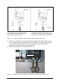
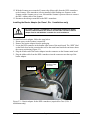
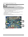
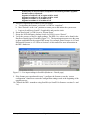
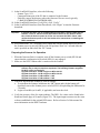
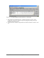
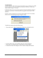
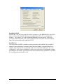
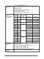
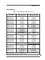
1
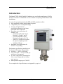
BARTON®
DPE+ Multi-Variable
Transducer
User Manual
Manual No. 2295451-01, Rev. 01
Important Safety Information
Symbols used in this manual:
This symbol identifies information about practices or circumstances that
can lead to personal injury or death, property damage, or economic loss.
WARNING
This symbol indicates actions or procedures which if not performed
correctly may lead to personal injury or incorrect function of the
instrument or connected equipment.
CAUTION
Terms used in this manual:
Note
Indicates actions or procedures which may affect instrument operation or
may lead to an instrument response which is not planned.
Technical Support:
Cameron
Measurement Systems Division
7944 10 Street NE
Calgary, AB T2E 8W1
Phone: 403-291-4814
Corporate Office:
14450 John F. Kennedy Blvd.
Houston, TX 77032
Phone: 1-800-654-3760; 281-582-9500
Fax: 281-582-9599
Barton is a registered trademark of Cameron International Corporation (“Cameron”).
NuFlo is a trademark of Cameron.
Copyright © 2009 Cameron International Corporation (“Cameron”). All
information contained in this publication is confidential and proprietary property of
Cameron. Any reproduction or use of these instructions, drawings, or
photographs without the express written permission of an officer of Cameron is
forbidden.
All Rights Reserved.
Printed in the United States of America.
Manual No. 2295451-01, Rev. 01
January 2009
Table of Contents
Section 1—Introduction ....................................................................................................................... 5
Hardware Modifications .......................................................................................................................... 6
Firmware Upgrade .................................................................................................................................. 6
Software Configuration ........................................................................................................................... 6
Section 2—DPE+ Installation .............................................................................................................. 7
Replacing the DPE+ Transducer ............................................................................................................ 7
Gasket Options ................................................................................................................................ 7
Installing the Barrier Adapter (for Class I, Div. 1 installations only) ....................................................... 9
Installing the Microcontroller (Scanner 1131 only) ............................................................................... 10
Section 3—Firmware Upgrade for Scanner 1140 ............................................................................ 11
Flashing Equipment and Firmware ....................................................................................................... 11
Flashing Procedure .............................................................................................................................. 11
Preparing the Scanner for Operation.................................................................................................... 12
Section 4—Firmware Upgrade for Scanner 1131 ............................................................................ 15
Flashing Equipment and Firmware ....................................................................................................... 15
Flashing Procedure .............................................................................................................................. 15
Preparing the Scanner for Operation.................................................................................................... 16
Section 5—Scanner Configuration via ScanWin Software ............................................................ 19
ScanWin B3.1.0W .......................................................................................................................... 19
ScanWin B3.0.0W .......................................................................................................................... 20
ScanWin B2.2.5W .......................................................................................................................... 21
ScanWin Lite .................................................................................................................................. 21
Appendix A—Specifications............................................................................................................ A-1
General Performance ......................................................................................................................... A-1
Environmental ..................................................................................................................................... A-1
Electrical Approvals for Scanner 1140 (Pending for Scanner 1131) .................................................. A-1
Appendix B—Part Numbers ............................................................................................................ B-1
January 2009
Page iii
Table of Contents
Table of Contents
Page iv
January 2009
Section 1
Introduction
The Barton® DPE+ Multi-Variable Transducer now used in the manufacture of NuFlo
Scanner 1140 and 1131 EFM/RTUs is also available for replacing failed DPEs in field
installations.
As a one-for-one replacement for the DPE, the DPE+ transducer offers:
• Easy installation with no tubing changes required
• Comparable power consumption ratings
• Accuracy and performance
specifications that are several times
better than those of the DPE
• Hazardous area certifications for
Scanner 1140
- CSA Intrinsically Safe Class I,
Division 1, Groups C and D
- CSA Non-incendive Class I,
Division 2, Groups A, B, C, D
- ANSI 12.27 Single Seal certified
for pressure ranges up to and
including 3000 psi
• Hazardous area certifications for
Scanner 1131 pending
Performance specifications match those of
the Scanner 2000 sensor. They include:
• Accuracy: +/- 0.05% of full scale
• Long-term drift: +/- 0.05% of URL per
year over a 5-year period.
• A “draft” range sensor, measuring 0 to
30-in. water column and 0 to 100-psi
static pressure
• Static pressure ranges up to 5300 PSI
For a complete list of specifications, see Appendix A, page A-1.
January 2009
Page 5
Section 1
Hardware Modifications
The following modifications may be required for DPE replacement:
• All Scanner 1131s require a new PIC controller (Part No. 9A-1131-0103T).
• All Scanner 1140s in Class I, Division 1 installations require an intrinsically safe barrier
adapter (Part No. 9A-30058901) between the Scanner and the DPE+ transducer. The
adapter is not required for Class I, Division 2 installations.
See Section 2 for step-by-step hardware installation instructions.
Firmware Upgrade
A firmware upgrade is required for all instruments upgraded with a Barton® DPE+
transducer. See Table 1.1 on page 6 to determine which firmware version is appropriate.
See Section 3 for instructions on upgrading Scanner 1140 firmware.
See Section 4 for instructions on upgrading Scanner 1131 firmware.
To save existing configuration file and report settings and restore them following a firmware
upgrade, use the “save configuration” and “restore configuration” functions in ScanWin or
ScanPC. If settings are not saved prior to reflashing the Scanner and a superboot is
performed, configuration settings will be lost and the Scanner must be reconfigured
following the firmware upgrade. Verify that the flow computer is calculating flow and gas
day hour is correct.
Table 1.1—Selection Chart for Scanner Firmware Upgrade
If using this model…
…and this firmware
Install this firmware
version (or later
version)
Configure with
this software
Scanner 1131
NFlo version 4.x
NFlo version 3.x
NGas version 3.x
NGas version 2.x
NFlo 4.4.0R
NFlo 3.2.4R
NGas 3.1.4R
NGas 2.7.4R
ScanWin
ScanPC
ScanPC
ScanPC
Scanner 1140
NFlo version 4.x
NFlo 4.4.0F
ScanWin
NFlo version 3.x
NGas version 3.x
NGas version 2.x
NFlo 3.2.4F
NGas 3.1.4F
NGas 2.7.4F
ScanPC
ScanPC
ScanPC
Software Configuration
The DPE+ multi-variable transducer can be configured using either ScanWin or ScanPC
interface software. Table 1.1 provides a guide for determining which interface software is
required for supporting the firmware version in use.
Section 1
Page 6
January 2009
Section 2
DPE+ Installation
This section provides step-by-step instructions for replacing a DPE in a Scanner 1140 or
Scanner 1131 with a DPE+ transducer.
The upgrade may require the following additional tasks:
• If used in a Class I, Div. 1 intrinsically safe installation, the installation of a barrier
adapter
• Upgrade of the PIC micro-controller (Scanner 1131 only)
New Scanner firmware is also required to support communications with the DPE+
transducer. See Sections 3 and 4 for instructions on flashing new firmware to the Scanner.
Replacing the DPE+ Transducer
Explosion Hazard. Do not disconnect equipment unless power has been
switched off or the area is known to be non-hazardous.
WARNING
Static electricity can damage the DPE+ transducer. Use proper anti-static
techniques to establish an earth ground (such as wearing anti-static wrist
strap or touching metal) prior to removing the DPE+ from the anti-static bag.
CAUTION
1.
2.
3.
4.
5.
6.
Power down the Scanner.
Remove the tubing or manifold from the DPE.
Attach a static ground strap to your wrist and a Scanner ground.
Remove the ground screw from the DPE nut inside the enclosure.
Loosen the DPE nut on the outside of the enclosure.
Remove the DPE nut inside the enclosure using a 1 11/16-in. or adjustable wrench. It may
be necessary to place a wrench on the DPE neck or body for leverage.
7. Unplug the DPE cable from the Scanner board.
8. Remove the DPE from the enclosure.
9. Examine the gaskets and replace as necessary to maintain a weatherproof enclosure. Two
gaskets are supplied with each DPE+.
Gasket Options
For metal enclosures, the gasket is installed between the DPE+ and the enclosure.
For fiber-reinforced plastic (FRP) enclosures, see options shown in Figure 2.1, page 8.
January 2009
Page 7
Section 2
Install a gasket between the enclosure and the
bottom bracket, and another gasket between the
bottom bracket and the DPE+ adapter.
Put 3 wraps of Teflon tape around the top ½ in. of
neck threads of the DPE+ adapter. Install the gasket
between the inside of the enclosure and the DPE nut.
Figure 2.1—Gasket installation options for fiber-reinforced plastic enclosures
10. Insert the top of the DPE+ transducer through the opening in the Scanner enclosure and
secure, using the DPE nut from inside the enclosure (Figure 2.2). Make sure the ground
screw is facing the front of the Scanner. The external nut from the original DPE
installation is no longer needed and may be discarded.
11. Reconnect the ground wire to the internal DPE nut.
Ground screw
Figure 2.2—Proper positioning of the DPE+ transducer (shown with a Scanner 1140)
Section 2
Page 8
January 2009
12. With the Scanner power turned off, connect the ribbon cable from the DPE+ transducer
to the Scanner. If the transducer is being installed while flashing new firmware to the
Scanner and the Scanner power is on, wait until the Scanner is powered down to connect
the DPE+ ribbon cable to the Scanner.
13. Reconnect the tubing or manifold to the DPE+ transducer.
Installing the Barrier Adapter (for Class I, Div. 1 installations only)
For Class I, Division 1 installations, an instrinsically safe barrier adapter
must be installed between the Scanner and the DPE+ transducer. Barrier
adapter Part No. 9A-30058901 is suitable for such installations.
WARNING
To install the barrier adapter, follow the steps below.
1. Ensure power to the Scanner is turned off.
2. Remove the barrier adapter from the packaging.
3. Locate the DPE connector in the bottom right corner of the main board. The “DPE” label
on the black decal on the extrusion that covers the main board inside the enclosure shows
the correct positioning (Figure 2.3).
4. Plug the female end of the barrier adapter into the connector on the Scanner main board.
5. Plug the ribbon cable from the DPE+ transducer into the connector near the top of the
barrier adapter.
Barrier adapter
with ribbon cable
connected
DPE label
Figure 2.3— Barrier adapter for the DPE+ transducer (required for Class I, Div. 1
installations only)
January 2009
Page 9
Section 2
Installing the Microcontroller (Scanner 1131 only)
The Scanner 1131 PIC microcontroller must be upgraded to Revision 3.5 or
higher for use with the Barton DPE+ transducer.
CAUTION
If two transducers are in use, both must be upgraded to DPE+. The
microcontroller will operate properly only when both DPEs are the same
model (both DPEs or both DPE+).
1. Power down the Scanner by moving the slider switch SW18 to the OFF position. (SW18
is located at top left-hand corner of the main board next to the ½ AA lithium battery.)
2. Remove the two PIC enable jumpers from the main board (Figure 2.4).
- Jumper CN16 is located below the power switch.
- Jumper CN11 is located near the PIC.
3. Carefully remove the PIC micro-controller using a special tool or a small screwdriver,
taking precautions to avoid cracking the plastic holder around the PIC.
4. Reinstall new PIC.
5. Reinstall jumpers CN16 and CN11.
6. Restore power to the Scanner by moving the slider switch SW18 to the ON position.
7. Start ScanWin/ScanPC and reset the clock.
PIC
Microcontroller
PIC Enable
Jumper CN16
PIC Enable
Jumper CN11
Figure 2.4—Microcontroller jumper locations
Section 2
Page 10
January 2009
Section 3
Firmware Upgrade for Scanner 1140
Flashing Equipment and Firmware
ScanFLASH version 1.0 or higher is recommended for loading new firmware into the
Scanner. Alternatively, Winsload may be used for loading new firmware.
Firmware version 4.0.0 files may be downloaded from the Cameron website
(www.c-a-m.com/flo). All other firmware upgrade files are available upon request from the
factory.
Flashing Procedure
1. Copy the firmware files to a directory on your computer hard drive. The following
directory is recommended, as it is the default directory for the ScanFlash program:
C:\BARTON\BDMS\DATA\FIRMWARE.
2. Start ScanWin or ScanPC and connect to the Scanner 1140.
3. Download all historical data from the Scanner 1140.
4. Save the Scanner configuration settings by selecting the Configuration Report option.
5. Turn the Scanner OFF by moving Switch 1 of SW4 (block of 8 switches furthest from the
terminal block) to the “shutdown” position.
Switch block SW4 is shown in Figure 3.1. For a close-up view of all eight switch
positions that make up SW4, see Figure 3.2, page 14.
Figure 3.1—Live input readings in ScanWin (Hardware – Details page)
January 2009
Page 11
Section 3
Figure 3.2—Block SW4, switches 1 through 8
6. If a configuration lock switch is installed, ensure it is in the unlocked position.
7. Close ScanWin or ScanPC.
8. Start ScanFLASH or alternatively, Winsload.
9. Move Switch 5 of SW4 to “program”.
10. Move Switch 6 of SW4 to “FPGA boot”.
11. In the ScanFLASH interface, select the following:
- Scanner Type: 1140
- Communications port of the PC that is connected to the Scanner
- Flash file (map to the directory where the firmware files are saved; typically,
C:\BARTON\BDMS\DATA\FIRMWARE)
12. In the ScanFLASH interface (Verify File), click “Verify.”
13. In the ScanFLASH interface (Start Download), click “Begin” to start the firmware
download.
Important
If desired, the DPE+ can be installed while the firmware is being loaded into the
Scanner. To do so, disconnect the DPE ribbon cable from the Scanner at this
time, while the Scanner power is off. Do not reconnect the DPE+ ribbon cable
unless the Scanner power is off. See Section 2 for instructions on installing the
DPE+ transducer.
14. Power up the Scanner 1140 by moving Switch 1 of SW4 to the “run” position. This will
start the process of erasing the old firmware.
Preparing the Scanner for Operation
1. When the firmware flash is complete, turn off the Scanner power by moving Switch 1 of
SW4 to the “shutdown” position.
2. Move Switch 5 of SW4 to “Flash protect”.
3. Move Switch 6 of SW4 to “app”.
4. Make sure the DPE+ ribbon cable is connected to the Scanner.
Section 3
Page 12
January 2009
Important
Depending on the version of the firmware that existed prior to the reflashing, the
Scanner may or may not require a superboot. The following firmware upgrades
DO NOT require a superboot:
Upgrade from NFLo 4.3.4F or higher to NFLo 4.4.0F
Upgrade from NFLo 3.2.1F or higher to NFLo 3.2.4F
Upgrade from NGas 3.1.3F to NGas 3.1.4F
Upgrade from NGas 2.7.3F to NGas 2.7.4F
5. If desired, superboot the Scanner to clear all settings.
a. To superboot the Scanner, set Switch 3 of SW4 to “superboot”.
b. Move Switch 1 to the “run” position to restore power and initiate the system reset.
c. Login to ScanWin (or ScanPC, if applicable) and reset the clock.
6. Ensure that Switch 3 of SW4 is set to “Restart Norm”.
7. Ensure the NVRAM battery backup Switch 4 of SW4 is set to “Protect”.
8. Verify the accuracy of the live input readings. The DPE+ live values can be found in the
Hardware Details page of ScanWin (Figure 3.3). The input/output resources are the same
as those established for the original DPE sensor. For example, Static Pressure is A12 and
Differential Pressure is A13. Refer to Section 5 of this manual for more information on
the DPE+ hardware.
Figure 3.3—Live input readings in ScanWin (Hardware – Details page)
9. If the Scanner was superbooted in step 3, configure the Scanner or use the “restore
configuration” function to restore the configuration settings saved at the beginning of the
upgrade process.
10. Calibrate the DPE+ transducer using ScanWin (or ScanPC for firmware versions 2.x and
3.x).
January 2009
Page 13
Section 3
Section 3
Page 14
January 2009
Section 4
Firmware Upgrade for Scanner 1131
Flashing Equipment and Firmware
ScanFLASH version 1.0 or higher is recommended for loading new firmware into the
Scanner. Alternatively, Winsload may be used for loading new firmware.
Firmware version 4.0.0 files may be downloaded from the Cameron website
(www.c-a-m.com/flo). All other firmware upgrade files are available upon request from the
factory.
Flashing Procedure
1. Copy the firmware files to a directory on your computer hard drive. The following
directory is recommended, as it is the default directory for the ScanFlash program:
C:\BARTON\BDMS\DATA\FIRMWARE.
2. Start ScanWin or ScanPC and connect to the Scanner 1131.
3. Download all historical data from the Scanner 1131.
4. Save the Scanner configuration settings by selecting the Save Scanner File option.
5. Power down the Scanner by moving the slider switch SW18 to the OFF position. (SW18
is located at top left-hand corner of the main board next to the battery; see Figure 4.1.)
6. If a configuration lock switch is installed, ensure it is in the unlocked position.
Figure 4.1—Scanner 1131 main board switch locations
7. Close ScanWin or ScanPC.
8. Start ScanFLASH or alternatively, Winsload.
January 2009
Page 15
Section 4
9. In the ScanFLASH interface, select the following:
- Scanner Type: 1131
- Communications port of the PC that is connected to the Scanner
- Flash file (map to the directory where the firmware files are saved; typically,
C:\BARTON\BDMS\DATA\FIRMWARE)
10. In the ScanFLASH interface (Verify File), click “Verify.”
11. In the ScanFLASH interface (Start Download), click “Begin” to start the firmware
download.
Important
If desired, the DPE+ can be installed while the firmware is being loaded into the
Scanner. To do so, disconnect the DPE ribbon cable from the Scanner at this
time, while the Scanner power is off. Do not reconnect the DPE+ ribbon cable
unless the Scanner power is off. See Section 2 for instructions on installing the
DPE+ transducer.
12. Press and hold the “PE” (Program Erase) button and with the button depressed, turn on
the Scanner power by moving SW18 to the ON position. Wait 2 to 3 seconds after the
unit is powered on and release the “PE” button.
Preparing the Scanner for Operation
1. When the firmware flash is complete, turn off the Scanner power switch (SW18) and
ensure that the configuration lock switch (SW16) is not engaged.
2. Make sure the DPE+ ribbon cable is connected to the Scanner.
Important
Depending on the version of the firmware that existed prior to the reflashing, the
Scanner may or may not require a superboot. The following firmware upgrades
DO NOT require a superboot:
Upgrade from NFLo 4.3.4R or higher to NFLo 4.4.0R
Upgrade from NFLo 3.2.1R or higher to NFLo 3.2.4R
Upgrade from NGas 3.1.3R to NGas 3.1.4R
Upgrade from NGas 2.7.3R to NGas 2.7.4R
3. If desired, superboot the Scanner to clear all settings.
a. To superboot the Scanner, hold down the “SB” button and with the button still
depressed, turn on the Scanner power switch (SW18). Keep holding the SB button for
5 seconds.
b. Login to ScanWin (or ScanPC, if applicable) and reset the clock.
4. Verify the accuracy of the live input readings. The DPE+ live values can be found in the
Hardware Details page of Scanwin (Figure 4.2). The input/output resources are the same
as those established for the original DPE sensor. Refer to Section 5 of this manual for
more information on the DPE+ hardware.
Section 4
Page 16
January 2009
Figure 4.2—Live input readings in ScanWin (Hardware – Details page)
5. If the Scanner was superbooted in step 3, configure the Scanner or use the “restore
configuration” function in ScanWin to restore the configuration settings saved at the
beginning of the upgrade process.
6. Calibrate the DPE+ transducer using ScanWin (or ScanPC for firmware versions 2.x and
3.x).
January 2009
Page 17
Section 4
Section 4
Page 18
January 2009
Section 5
Scanner Configuration via ScanWin Software
Following an upgrade to the DPE+ transducer, Scanners can be configured using any of
several versions of ScanWin software. This section discusses some of the differences the
operator can expect as a result of the sensor upgrade.
ScanWin B3.1.0W
Scanner firmware version 4.4.0 works best with ScanWin version B3.1.0W.
A Properties tab in the Hardware page will display three DPE+ transducer parameters (MVT
Static Pressure parameters) that are not available in the Hardware Details tab. They are MVT
cell temperature, serial number, and status.
This MVT Static
Pressure Field...
Indicates...
MVT Cell Temperature
This is the internal temperature of the DPE+ sensor electronics. This
value is live and should always be changing, even though the change
may only be in second or third decimal place.
Serial Number
The first 10 digits to the left of the “V” match the numeric values of the
serial number stamped on the DPE+ cell. Example MV28C0413B is
displayed as 0000280413. The number to the right of the “V” is the
DPE+ firmware version.
Status
The status indicates the communication quality in %, between the
Scanner EFM/RTU and the DPE+. If there are any missed communications, this value will drop from the normal reading of 100%.
January 2009
Page 19
Section 5
ScanWin B3.0.0W
As with ScanWin B3.1.0W, the Properties tab in the Hardware page will display three DPE+
transducer parameters that are not available in the Hardware Details tab. See the screen
capture and table on page 17 for details.
ScanWin B3.0.0W users are not required to upgrade to the latest ScanWin Pro software to
communicate with Scanner 1140 units that have been upgraded with the Barton® DPE+
transducer.
Firmware versions 4.4.0R and 4.4.0F can be used with ScanWin version 3.0.0 and older
software, however the following message will appear on login:
To disable this warning, perform the following steps:
1. Ensure that Options > Show Communications Window has a checkmark beside it.
2. From the Options menu, select ScanWin settings, then click the Debug tab.
3. Ensure there is no checkmark beside “Default Firmware Warning Dialog.”
4. Click the Save button. The dialog box will close and the warning will be disabled.
Section 5
Page 20
January 2009
ScanWin B2.2.5W
ScanWin B2.2.5W will work with NFLo M4.4.0 firmware, with a BDMGR.DLL dated 2002
Aug 1 or newer. New data ID’s that have been added since NFLo 4.3.0—primarily for
ScanPLC , the Scanner 1141, and the Ethernet/Bluetooth accessory board—will not be
accessible with ScanWin B2.2.5W. MVT communication status on the MVT SP hardware
input is also inaccessible with ScanWin B2.2.5W.
ScanWin Lite
The conversion to the DPE+ transducer can be performed with ScanWin Lite provided no
changes to network settings, accessories (other than local display) or hardware details are
required; these functions are not supported in the Lite version. In ScanWin Lite, the “save
configuration” and “restore configuration” features save and restore all configurable settings
including network settings. Any functions that can be performed with ScanWin Lite on NFLo
4.3.0 can be performed on NFLo 4.4.0.
January 2009
Page 21
Section 5
Section 5
Page 22
January 2009
Appendix A
Specifications
General Performance
•
•
•
Provides linearized digital data
- Static pressure
- Differential pressure
NACE-compliant units also available (See Table A.2, page A-3, for bolt specifications)
User-adjustable sample time and damping
Environmental
•
•
•
Operating Temperature: -40°F to +158°F (-40°C to +70°C)
Process (Cell) Temperature: -40°F to +176°F (-40°C to +80°C)
Relative Humidity: 0-95%, non-condensing
Electrical Approvals for Scanner 1140 (Pending for Scanner 1131)
•
•
•
CSA Intrinsically Safe, Class I, Division 1, Groups C & D
CSA Non-incendive, Class I, Division 2, Groups A, B, C, D
ANSI 12.27 Single Seal certified for pressure ranges up to and including 3000 psi
January 2009
Page A-1
Appendix A
Table A.1—Measurement Accuracy
Differential Pressure
Accuracy
Effect on Differential
Pressure
for a 100-psi Change
in Static Pressure
Stability: Long-term drift is less than ±0.05% of upper range limit (URL) per
year over a 5-year period
Accuracy (30 In. H2O)
• ±0.10% for spans ≥10% of the sensor URL
• ±(0.010) (URL÷SPAN) for spans <10% of the sensor URL
Accuracy (200 to 840 In. H2O)
• ±0.05% for spans ≥10% of the sensor URL
• ±(0.005) (URL÷SPAN) for spans <10% of the sensor URL
SP/SWP
DP
(PSIA) (IN H2O)
Max. Overrange
Pressure
(PSIA)
Zero Shift
Span Shift
100
30
150
±0.05% of URL
±0.01% of reading
300
200
450
±0.007% of URL
±0.01% of reading
300
840
±0.002% of URL
±0.01% of reading
500
200
750
±0.010% of URL
±0.01% of reading
1500
200
2250
±0.010% of URL
±0.01% of reading
1500
300
±0.004% of URL
±0.01% of reading
1500
400
±0.004% of URL
±0.01% of reading
1500
840
±0.004% of URL
±0.01% of reading
3000
200
±0.010% of URL
±0.01% of reading
300
300
±0.004% of URL
±0.01% of reading
3000
400
±0.004% of URL
±0.01% of reading
3000
840
±0.004% of URL
±0.01% of reading
5300
200
±0.010% of URL
±0.01% of reading
5300
300
±0.004% of URL
±0.01% of readi
5300
400
±0.004% of URL
±0.01% of reading
5300
840
±0.004% of URL
±0.01% of reading
4500
7420
Static Pressure
Accuracy
Accuracy (500 psia)
• ±0.05% for spans ≥5% of the sensor URL
• ±(0.0025) (URL÷SPAN) for spans <5% of the sensor URL
Accuracy (300, 1500, 3000 and 5300 psia)
• ±0.05% for spans ≥10% of the sensor URL
• ±(0.0025) (URL÷SPAN) for spans <10% of the sensor URL
Temperature
Performance
±0.25% of full scale over full operating temperature range
Appendix A
Page A-2
January 2009
Table A.2—MVT Pressure Limits and Bolt Specifications
SP/SWP
(PSIA)
a
b
Max.
Overrange
DP
Pressure
(IN H2O)
(PSIA)
Standard
Bolts
Limited NACE Bolts
a
(not for offshore)
Full NACE Bolts
100
30
150
B7 or 316 SS
(with SS vent plug)
B7M
(no vent plug)
B7M
(with Hastelloy vent
plug)
300
200
450
300
840
B7 or 316 SS
(with SS vent plug)
B7M
(no vent plug)
B7M
(with Hastelloy vent
plug)
500
200
750
B7 or 316 SS
(with SS vent plug)
B7M
(no vent plug)
B7M
(with Hastelloy vent
plug)
1500
200
2250
1500
300
B7 or 316 SS
(with SS vent plug)
B7M
(no vent plug)
B7M
(with Hastelloy vent
plug)
1500
400
1500
840
3000
200
4500
3000
300
B7 or 17-4 SS
(with SS vent plug)
Inconel
(no vent plug)
Inconel
(with Hastelloy vent
plug)
3000
400
3000
840
5300
200
7420
5300
300
B7
(with SS vent plug)
5300
400
5300
840
b
b
Inconel
(no vent plug)
b
Inconel
(with Hastelloy vent
plug)
A regular stainless steel plug is substituted for the vent plug in limited NACE units.
Not available with Canadian CRN or ANSI 12.27 Single Seal certification.
January 2009
Page A-3
Appendix A
Appendix A
Page A-4
January 2009
Appendix B
Part Numbers
Table B.1—Barton® DPE+ Multi-Variable Transducers
DPE+ range
100PSIA,30IN H20
300PSIA,200IN H20
300PSIA,840IN H20
500PSIA,200IN H20
1500PSIA,200IN H20
1500PSIA,300IN H20
1500PSIA,400IN H20
1500PSIA,840IN H20
3000PSIA,200IN H20
3000PSIA,300IN H20
3000PSIA,400IN H20
3000PSIA,840IN H20
5300PSIA,200IN H20
5300PSIA,300IN H20
5300PSIA,400IN H20
5300PSIA,840IN H20
Standard
316SS body / B7 bolts
Standard
316SS body / 316SS bolts
9A-30058041
9A-30058042
9A-30058075
9A-30058076
9A-30058043
9A-30058077
9A-30058078
9A-30058079
9A-30058044
9A-30058080
9A-30058081
9A-30058082
b
9A-30058045
b
9A-30058083
b
9A-30058084
b
9A-30058085
9A-30058097
9A-30058098
9A-30058099
9A-30058100
9A-30058101
9A-30058102
9A-30058103
9A-30058104
b
9A-30058105
b
9A-30058106
b
9A-30058107
b
9A-30058108
not available
not available
not available
not available
a
100PSIA,30IN H20
300PSIA,200IN H20
300PSIA,840IN H20
500PSIA,200IN H20
1500PSIA,200IN H20
1500PSIA,300IN H20
1500PSIA,400IN H20
1500PSIA,840IN H20
Limited NACE
B7M Bolts (not for offshore)
Full NACE
B7M Bolts / Hastelloy Vent Plug
9A-30058641
9A-30058642
9A-30058675
9A-30058676
9A-30058643
9A-30058677
9A-30058678
9A-30058679
9A-30058046
9A-30058047
9A-30058086
9A-30058087
9A-30058048
9A-30058088
9A-30058089
9A-30058090
a
3000PSIA,200IN H20
3000PSIA,300IN H20
3000PSIA,400IN H20
3000PSIA,840IN H20
5300PSIA,200IN H20
5300PSIA,300IN H20
5300PSIA,400IN H20
5300PSIA,840IN H20
a
b
Limited NACE
Inconel Bolts (not for offshore)
Full NACE
Inconel Bolts / Hastelloy Vent Plug
9A-30058644
9A-30058680
9A-30058681
9A-30058682
b
9A-30058645
b
9A-30058683
b
9A-30058684
b
9A-30058685
9A-30058049
9A-30058091
9A-30058092
9A-30058093
b
9A-30058050
b
9A-30058094
b
9A-30058095
b
9A-30058096
A regular stainless steel plug is substituted for the vent plug in limited NACE units.
Not available with Canadian CRN or ANSI 12.27 Single Seal certification.
January 2009
Page B-1
Appendix B
Table B.2—Scanner Components for DPE Upgrade
Description
Part Number
Intrinsically Safe Barrier Adapter, for CSA-certified Class I, Div. 1, Groups
C, D installations (suitable for Scanner 1131 or Scanner 1140)
9A-30058901
Microcontroller, PIC, version 3.5 (required for DPE upgrade of Scanner
1131)
9A-1131-0103T
Appendix B
Page B-2
January 2009
WARRANTY - LIMITATION OF LIABILITY: Seller warrants only title to the products,
software, supplies and materials and that, except as to software, the same are free
from defects in workmanship and materials for a period of one (1) year from the date
of delivery. Seller does not warranty that software is free from error or that software
will run in an uninterrupted fashion. Seller provides all software "as is". THERE ARE
NO WARRANTIES, EXPRESS OR IMPLIED, OF MERCHANTABILITY, FITNESS
OR OTHERWISE WHICH EXTEND BEYOND THOSE STATED IN THE
IMMEDIATELY PRECEDING SENTENCE. Seller's liability and Buyer's exclusive
remedy in any case of action (whether in contract, tort, breach of warranty or
otherwise) arising out of the sale or use of any products, software, supplies, or
materials is expressly limited to the replacement of such products, software, supplies,
or materials on their return to Seller or, at Seller's option, to the allowance to the
customer of credit for the cost of such items. In no event shall Seller be liable for
special, incidental, indirect, punitive or consequential damages. Seller does not
warrant in any way products, software, supplies and materials not manufactured by
Seller, and such will be sold only with the warranties that are given by the
manufacturer thereof. Seller will pass only through to its purchaser of such items the
warranty granted to it by the manufacturer.