1
BARTON®
®
Scanner 1131
Measurement RTU
Hardware Manual
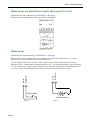
Above: Scanner 1131 rack-mount
Right: Scanner 1131S with dual DPE+ units
Manual No. 9A-30165013, Rev. 02
WARRANTY
The Company warrants all products of its manufacture and bearing its nameplate for a period of one year after
date of shipment from its factory to be free from defects in material and workmanship subject to the following:
The Company’s liability under this warranty is limited in the sole and absolute discretion of the Company to
refunding the purchase price, to repairing, or to replacing parts shown to the satisfaction of the Company to have
been defective when shipped and then only if such defective parts are promptly delivered to its factory,
transportation charges prepaid. This warranty is absolutely void if written notification is not given by Purchaser
to Company within one year after said date of shipment.
This warranty applies only if the products have been installed, operated and maintained in accordance with the
Company’s recommendations and the products have not been misused, neglected, damaged by flood, fire or act
of God, or modified or repaired, other than by the Company.
Where the Company has manufactured the products to a design of the purchaser, no liability is accepted by the
Company for design errors, which remain the responsibility of the Purchaser.
This warranty is expressly in lieu of all other warranties, obligations, conditions or liabilities, expressed or
implied by the Company or its representative. All statutory or implied warranties and conditions, other than
title, are hereby expressly negated and excluded. The Company’s liability stated herein cannot be altered,
enlarged, or extended except in writing by an officer of the Company. The Company shall be under no liability
in contract or otherwise for any loss, damage, death or injury arising directly or indirectly out of the supply,
failure to supply, or use of the products.
Replacement parts will be invoiced in the regular way with invoices subject to adjustment after the parts claimed
defective are examined at our factory. The Company reserves the right to make such changes in details of
design, construction of product arrangement as shall, in its judgment, constitute any warranty of the Company’s
supplier of such products.
The Company and its representatives will furnish, upon request, data and engineering services relating to the
application or use of its products. It will not be responsible and it does not assume any liability whatsoever for
damages of any kind sustained either directly or indirectly by any person in the adoption or use of such data, any
errors or omissions in such data, or engineering services in whole or in part.
WARRANTY LIMITATION
The Company manufactures products which satisfy the exact definition of Quality, that is, they meet the
specifications as advertised or as stated by our customer. The products are intended to be used in accordance
with the specification and applications described in this document.
A limited warranty applies to Cameron’s Measurement Systems Division products. The Company will assume
responsibilities for obligations, related to its products, which are specifically noted within the written warranty
for a specific product. However, the Company will not be liable for any loss, damage, cost of repairs, incidental
or consequential damages of any kind whether or not they are based upon expressed or implied warranty,
contract, negligence, or strict liability arising in connection with the design, manufacture, sale use or repair of
the products, if they are used outside the constraints of recommended usage as set forth herein.
Any use or application that deviates from the stated performance specification is not recommended and could
render the instrument unsafe.
The Company should be advised of any apparent deviation or deficiency from specifications including safety
related deficiencies, at the above factory address, to the attention of the Marketing Department. A return
authorization will be issued, where applicable, for goods returned for inspection, calibration or repair, under
warranty.
PRODUCT WARRANTY STATEMENT
The warranty applicable to this product is stated at the beginning of this manual.
Should any problem arise after-delivery, please contact Cameron’s Measurement Systems Division HelpDesk at
1-877-805-7226 or the Customer Service department during normal business hours at (403) 291-4814.
Before installing the instrument, become familiar with the installation instructions presented in Section 1 Hardware.
Also, be aware of the following important notices that appear throughout the manual:
DANGER notes indicate the presence of a hazard that will cause severe personal injury, death, or substantial
property damage if the warning is ignored.
WARNING notes indicate the presence of a hazard that can cause severe personal injury, death, or substantial
property damage if the warning is ignored.
CAUTION notes indicate the presence of a hazard, which will or can cause minor personal injury or property
damage if the warning is ignored.
Please be aware that the above notices appear on the following pages:
•
Page 13
•
Page 15
•
Page 102
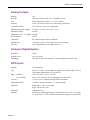
REVISIONS
Date
Description
By
June 1998
Release
A. Seeger, BIL
November, 1999
Major revision
P. Lee, BIL
January, 2000
Minor revisions
P. Lee, BIL
October, 2001
Major revision including new format
P. Lee, BIL
May, 2003
Updated to include the Scanner 1131C
P. Lee, BIL
Oct, 2005
Minor revisions
A. Seeger
September, 2008
Corporate name change
K. Metzer
July, 2010
Updated to show substitution of DPE+ for DPE cell, EB02 modem
board option; other minor changes
K. Metzer
Barton, MVX, ScanBase, Scanner, ScanOp, ScanPC and ScanWin are trademarks or registered trademarks of Cameron International Corporation,
Houston, Texas, USA.
Intel is a registered trademark of the Intel Corporation.
Windows is a registered trademark of Microsoft Corporation in the U.S.A. and other countries.
TABLE OF CONTENTS
INTRODUCTION............................................................................................................11 Overview .............................................................................................................................................................. 11 1: INSTALLATION.........................................................................................................13 Installing the Scanner 1131 .................................................................................................................................. 13 Quick Start............................................................................................................................................................ 13 Operating/Storage Limitations ............................................................................................................................. 14 Unpacking............................................................................................................................................................. 14 Mounting .............................................................................................................................................................. 14 Piping.................................................................................................................................................................... 14 Power Supply Connection .................................................................................................................................... 14 Power Supply........................................................................................................................................................ 15 Class I, Div. 1 Battery Charger / Power Supply ............................................................................................... 15 Class I, Div. 2 Power Supplies.......................................................................................................................... 18 24-VDC Power Supply ................................................................................................................................. 18 12 Volt Battery Charger ................................................................................................................................ 19 Solar Panel Installation......................................................................................................................................... 20 Solar Panel Connection ................................................................................................................................. 20 Enclosure Options ................................................................................................................................................ 21 Scanner 1131C .............................................................................................................................................. 21 Scanner 1131S............................................................................................................................................... 21 Flashing the Scanner............................................................................................................................................. 22 Getting Ready to Flash ..................................................................................................................................... 22 Configuration Lock Switch ........................................................................................................................... 23 Start Flashing ................................................................................................................................................ 24 Flashing with ScanLoad (in Windows)............................................................................................................. 24 Flashing with WinsLoad (in Windows) ............................................................................................................ 26 Installing WinsLoad (MS Windows) ............................................................................................................ 26 Using WinsLoad............................................................................................................................................ 26 Flashing with ScanLoad (DOS) ........................................................................................................................ 27 Installing ScanLoad Version 2.2 ................................................................................................................... 27 Using ScanLoad ............................................................................................................................................ 28 Troubleshooting the Flashing Procedure .......................................................................................................... 29 Startup Procedure ................................................................................................................................................. 29 Jumper Settings................................................................................................................................................. 29 Superbooting the Scanner ................................................................................................................................. 31 2: MAIN BOARD AND WIRING ..................................................................................33 Main Circuit Board’s Major Components ............................................................................................................ 33 Major Chips ...................................................................................................................................................... 33 Jumpers ............................................................................................................................................................. 34 Page v
Scanner 1131 Hardware Manual
Switches ............................................................................................................................................................ 34 Power Switch ................................................................................................................................................ 35 The NVRAM Erase Switch........................................................................................................................... 35 The Flash Erase Switch ................................................................................................................................. 35 Transmitter Power Supply Switch (to Vtx)................................................................................................... 36 Total Transmitter Supply Output .................................................................................................................. 36 Main Board Wiring Diagrams .......................................................................................................................... 36 Six Analog Board .......................................................................................................................................... 37 Twelve Analog in Single-Ended Board ........................................................................................................ 38 Analog Transmitter Inputs ............................................................................................................................ 39 Six Analog Input Option............................................................................................................................ 39 Twelve Analog Input Option..................................................................................................................... 40 Analog 4-20 mA Transmitter .................................................................................................................... 41 Analog 1-5 Vdc Transmitter...................................................................................................................... 42 RTD Inputs (Resource A27, A28)................................................................................................................. 42 Pulse Inputs (Resources A05, A06) .............................................................................................................. 43 2-Wire Preamplifier (818A Current Loop Mode) ..................................................................................... 44 3-Wire Preamplifier Frequency Input........................................................................................................ 45 Magnetic Pickup Coil ................................................................................................................................ 46 Proximity Switch ....................................................................................................................................... 46 Contact Closure ......................................................................................................................................... 47 Open Collector........................................................................................................................................... 47 Status Inputs and Status/Pulse Outputs (Resources A7 to A12) ................................................................... 48 Status Inputs .................................................................................................................................................. 48 Status/Pulse Outputs...................................................................................................................................... 49 Analog Output (Resources A13, A14) .......................................................................................................... 49 Console Serial Port (Resource A01) ............................................................................................................. 50 Auxiliary Serial Port (Resources A02, A03 and A04) .................................................................................. 52 ScanPC Direct Connection ........................................................................................................................ 55 ScanPC Modem Connection...................................................................................................................... 56 ScanPol / ScanOp Direct Connection ........................................................................................................ 57 ScanPol / ScanOp Modem Connection ..................................................................................................... 58 3: EXPANSION BOARDS ..............................................................................................59 Expansion Boards................................................................................................................................................. 59 Analog and Status Output (AS01) ........................................................................................................................ 60 Specification ..................................................................................................................................................... 60 General .......................................................................................................................................................... 60 Analog Outputs ............................................................................................................................................. 60 Status/Pulse Outputs...................................................................................................................................... 60 Wiring Diagrams............................................................................................................................................... 61 Isolated Wiring Diagrams ............................................................................................................................. 62 Non-Isolated Wiring Diagrams ..................................................................................................................... 63 Communications and Analog Output (CAO1) ..................................................................................................... 64 Specifications.................................................................................................................................................... 64 General .......................................................................................................................................................... 64 Page vi
Table of Contents
July 2010
Serial Communications ................................................................................................................................. 64 Analog Outputs ............................................................................................................................................. 65 Field Wiring Termination.............................................................................................................................. 65 Options .......................................................................................................................................................... 65 Installation ........................................................................................................................................................ 65 Wiring Diagrams............................................................................................................................................... 66 CAO1 Setup.......................................................................................................................................................... 67 Analog Outputs ................................................................................................................................................. 67 Communications ............................................................................................................................................... 68 Scanner Settings................................................................................................................................................ 70 Communications and Status (Digital) Input/Output (CDO1) ............................................................................... 71 Specifications.................................................................................................................................................... 71 General .......................................................................................................................................................... 71 Serial Communications ................................................................................................................................. 71 Status Inputs and Status/Pulse Outputs ......................................................................................................... 71 Field Wiring Termination.............................................................................................................................. 72 Options .......................................................................................................................................................... 72 Installation ........................................................................................................................................................ 73 Wiring Diagram ................................................................................................................................................ 73 CDO1 Setup...................................................................................................................................................... 74 Communications (Terminals 1-9) ................................................................................................................. 74 Digital I/O Circuits (Terminals 10-17).......................................................................................................... 76 Scanner Settings ............................................................................................................................................ 76 Status I/O, Pulse I/O Digital Channels (DIO1) .................................................................................................... 77 Specifications.................................................................................................................................................... 77 General .......................................................................................................................................................... 77 Status and Pulse Input ................................................................................................................................... 78 Phase Discriminator ...................................................................................................................................... 78 Pulse Comparators ........................................................................................................................................ 78 Status and Pulse Output Specifications ......................................................................................................... 79 Installation ........................................................................................................................................................ 79 Wiring Diagram and Board Layout .................................................................................................................. 80 Circuit Description............................................................................................................................................ 81 I/O Circuit Description.................................................................................................................................. 81 Threshold Level Switches (SW1 through SW5) ........................................................................................... 81 Mode of Operation Switches (SW6 through SW10)..................................................................................... 82 Phase Discriminator and Level B Pulse Security.............................................................................................. 83 1131 Phase Discrimination Configuration Procedure ................................................................................... 83 Level B Pulse Security .................................................................................................................................. 84 Phase Discrimination .................................................................................................................................... 84 Ethernet–Bluetooth Expansion Board (EB02) ..................................................................................................... 85 Ethernet Communication .................................................................................................................................. 85 Bluetooth Communication ................................................................................................................................ 86 Specifications.................................................................................................................................................... 86 Page vii
Scanner 1131 Hardware Manual
4: LOCAL DISPLAY MENU PATH (NFLO & IGAS 4.X) ........................................87 Basic Operation .................................................................................................................................................... 87 Moving the Cursor ............................................................................................................................................ 87 Opening and Closing Pages .............................................................................................................................. 87 Calculated or Live Values................................................................................................................................. 88 Default Values .................................................................................................................................................. 88 Entered Text or Values ..................................................................................................................................... 88 Selecting............................................................................................................................................................ 88 "Details" Page ................................................................................................................................................... 88 Function Keys ................................................................................................................................................... 88 Display Units................................................................................................................................................. 89 Local Display Menu Paths.................................................................................................................................... 90 Summary Pages .................................................................................................................................................... 91 Alarms Page.......................................................................................................................................................... 91 Alarm Acknowledgment................................................................................................................................... 91 Alarm Types ..................................................................................................................................................... 92 Alarm Status ..................................................................................................................................................... 92 Orifice Plate Change............................................................................................................................................. 93 Gas Data (Composition) Change.......................................................................................................................... 95 Clock / Calendar ................................................................................................................................................... 96 System Configuration........................................................................................................................................... 96 Node Information.............................................................................................................................................. 96 Systems Settings ............................................................................................................................................... 97 Utilities ................................................................................................................................................................. 99 5: TROUBLESHOOTING ............................................................................................101 Analog Inputs and Outputs ................................................................................................................................. 101 General Troubleshooting .................................................................................................................................... 101 Transmitter Voltage............................................................................................................................................ 102 Main Battery Voltage ......................................................................................................................................... 102 NVRAM Lithium Battery Voltage ..................................................................................................................... 104 6: DPE+ INSTALLATION ...........................................................................................105 DPE+ Installation ............................................................................................................................................... 105 Replacing a DPE with a DPE+ Transducer .................................................................................................... 105 Gasket Options ............................................................................................................................................ 106 Installing the Barrier Adapter (for Class I, Div. 1 installations only)............................................................ 107 Installing the Microcontroller ......................................................................................................................... 108 7:PRINCIPLES OF OPERATION ..............................................................................109 Central Processing Unit (CPU)........................................................................................................................... 109 Clocks ................................................................................................................................................................. 109 The Watchdog Timer.......................................................................................................................................... 109 Page viii
Table of Contents
July 2010
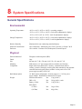
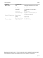
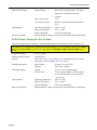
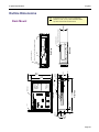
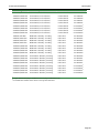
Memory .............................................................................................................................................................. 110 Field Programmable Gate Array......................................................................................................................... 110 Hardware Write Protection................................................................................................................................. 111 Power Management ............................................................................................................................................ 111 Analog Inputs ..................................................................................................................................................... 111 RTD Inputs ......................................................................................................................................................... 112 Pulse Inputs ........................................................................................................................................................ 112 Barton DPE+ Multi-Variable Transducer........................................................................................................... 112 Front Panel.......................................................................................................................................................... 113 Standard Display and Keypad......................................................................................................................... 113 Extended Function Keypad............................................................................................................................. 115 8: SYSTEM SPECIFICATIONS..................................................................................117 General Specifications........................................................................................................................................ 117 Environmental................................................................................................................................................. 117 Physical........................................................................................................................................................... 117 Computer ........................................................................................................................................................ 118 Communications ............................................................................................................................................. 118 Communications Expansion Boards ............................................................................................................... 120 I/O Expansion ................................................................................................................................................. 121 Display ............................................................................................................................................................ 121 Local Keyboard............................................................................................................................................... 121 Keypad (Extended Functions)......................................................................................................................... 121 Battery Charger/Power Supply ....................................................................................................................... 121 12 Vdc Charger / Power Supply Board for Div. 1 Areas ............................................................................ 121 12 Vdc Charger / Power Supply Board for Div. 2 Areas ............................................................................ 122 24 Vdc Power Supply for Div. 2 Areas....................................................................................................... 124 Electrical Inputs and Outputs Specifications...................................................................................................... 125 Analog Inputs.................................................................................................................................................. 125 Analog Outputs ............................................................................................................................................... 126 Analog to Digital System................................................................................................................................ 126 RTD Inputs ..................................................................................................................................................... 126 Status Inputs, Status and Pulse Outputs.......................................................................................................... 127 Pulse Inputs..................................................................................................................................................... 128 DPE+ Multi-Variable Transducer................................................................................................................... 129 Order Code ......................................................................................................................................................... 131 Outline Dimensions ............................................................................................................................................ 135 Rack Mount..................................................................................................................................................... 135 Scanner 1131C (Front View with Single DPE) .............................................................................................. 136 Scanner 1131C (Front View with Two DPE's)............................................................................................... 137 Scanner 1131C (Side Views with Universal Mount)...................................................................................... 138 Scanner 1131S ................................................................................................................................................ 139 9: PARTS LISTS AND DRAWINGS...........................................................................141 Standard Enclosure (1131S) ............................................................................................................................... 141 Page ix
Scanner 1131 Hardware Manual
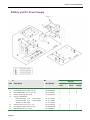
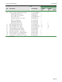
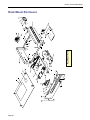
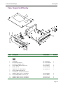
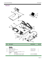
DPE+ Multi-Variable Transducer................................................................................................................... 144 Battery and DC Power Supply........................................................................................................................ 146 Rack Mount Enclosure ....................................................................................................................................... 148 Case, Keypad and Display .............................................................................................................................. 149 Boards ............................................................................................................................................................. 151 APPENDIX A: DRAWINGS ........................................................................................153 Page x
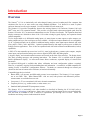
Introduction
Overview
The Scanner® 1131 is an intrinsically safe solar-charged, battery-powered, weatherproof flow computer that
calculates flow for two or more meter runs using standard algorithms. It is housed in a metal or plastic
enclosure that can be wall or pipe mounted. It is also available in a rack mount style.
The Scanner 1131 provides compatibility between the existing Scanner 1130 enclosure, Scanner 1140 style
DPE® units, and 1130 expansion boards. This provides a logical board replacement upgrade path from the
Scanner 1130 to the 1131, as numerous enhancements over the 1130 have been made. The expansion board and
display connectors are identical to those of the 1130 so that existing keypads, displays, and expansion boards
remain compatible.
Twelve single-ended or six differential analog inputs, six status inputs or status outputs or pulse outputs, two
analog outputs and up to four serial ports are now available. All input and output channels are user-assignable.
Up to 2 expansion boards can be added for additional analog outputs, status input/output channels and serial
ports (ASO1, CDO1, CAO1 and DIO1). Optimal expanded memory and math co-processor are available for
multiple flowrun applications. There is also an expansion board with serial to Ethernet and Bluetooth (wireless)
capabilities.
A PIC16C74 microcontroller processes low level I/O, scans keyboard entry, generates pulse outputs, samples
status inputs, and performs the analog conversion to digital of RTD, DPE, and analog inputs.
A keypad, display, and external terminal connector are located on the front of the enclosure. The display shows
flow data, operating messages, and operating instructions. The Scanner 1131 is available with an optional
backlit alphanumeric display. An auto-scroll feature allows continuous, sequential display of selected flow
parameters.
An optional full-keypad is available that allows calibration and most configuration without a terminal.
However, a terminal is required for downloading data and information. A terminal is an IBM compatible PC
running ScanPC or ScanWin™ configuration software. Terminals are connected through an external port
(located on the front or bottom of the enclosure) or hard-wired internally.
Compatible input devices include:
•
Barton DPE+ cell (pressure and differential pressure in one transducer). The Scanner 1131 can support
one or two DPE+ cells. When Barton DPE+ cells are used, both pressure and differential pressure
measurements are available from one unit.
•
Low power (1-5V) or conventional (4-20 mA) electronic transmitters
•
Frequency devices (e.g., turbine meters, or mass meters, etc.)
•
Standard 100Ω platinum RTD (temperature) sensors
The Scanner 1131 is intrinsically safe when installed as described in Drawing 9A-1131-11002 (refer to
APPENDIX A: Drawings) with barriers. Some power sources and input/output devices are not Intrinsically
Safe and must be installed to Class I, Division 2 requirements per drawing 9A-1131-11022. Please see
installation and wiring sections in this manual for details.
Page 11
Scanner 1131 Hardware Manual
A variety of software programs are available for configuring, monitoring, downloading, retrieving data, reading
and creating reports from collected data:
ScanWin™ - ScanWin is a Windows™-based software program that is used to monitor, configure, and
download Device Measurement RTU data on-site. Data is displayed graphically and in tables. Reports
can also be printed from ScanWin.
ScanPC™ - ScanPC™ is a DOS-based software program for a PC that is used to monitor, configure,
and download Scanner data on-site. Scanner files can be printed in a universal report format or output
in either comma separated, or tab separated text formats. All report files are readily imported into
spreadsheet and database software programs.
ScanBase™ - ScanBase™ is a graphical editing software program that simplifies the management of
complex electronic flow data. Months of hourly history can be viewed for trending and analysis. Color
codes and Windows point-and-click operations make learning and using the graph, tables, and
spreadsheet views easy.
The original flow history is always preserved. Edits are saved with the automatic audit trails, which include a
required comment explaining the reason for the edit. Reports and data export functions allow rapid distribution
of ScanBase data to other users or interface with other software programs.
Page 12
1: Installation
Installing the Scanner 1131
CAUTION
POWER TO THE SCANNER 1131 MUST BE TURNED OFF PRIOR TO THE REMOVAL OF ANY
ELECTRONIC CIRCUIT BOARDS OR DAMAGE TO THE SCANNER MAY RESULT.
CIRCUIT BOARDS ARE SUBJECT TO DAMAGE IF EXPOSED TO STATIC ELECTRICITY.
HANDLING AND INSTALLATION OF CIRCUIT BOARDS MUST BE PERFORMED IN AN
ENVIRONMENT FREE OF STATIC ELECTRICITY AND THE OPERATOR MUST BE
GROUNDED.
WHEN CIRCUIT BOARDS ARE REMOVED FROM THE SCANNER 1131, THEY MUST BE
PLACED IN PROTECTIVE CONDUCTIVE ENVELOPES.
Note:
Circuit boards returned to Cameron’s Measurement Systems Division factory for repair must be
properly packed for static protection or they will not be covered by the Cameron warranty.
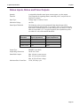
Quick Start
The following chart suggests a sequence for the installation of the Scanner 1131:
Step
1
2
3
4
5
6
Description
Unpack the Scanner
Mounting the flow computer
Connect to pipes
Connect power supply
Flash the Scanner (if changing installed firmware)
Superboot and configure the Scanner
Superboot
Connect inputs and outputs
Configure the EFM/RTU
Reference Section
Page 14
Page 14
Page 14
Page 14
Page 22
Page 31
Page 33
See Section 3 of NGas/NFlo/IGas manual or Chapter 2 of
the ScanWin manual.
Page 13
Scanner 1131 Hardware Manual
Operating/Storage Limitations
Temperature
The instrument is not to be subjected to ambient or operating temperatures beyond the
range listed in the specifications.
Static Electricity
The circuit boards are not to be subjected to any source of external static electricity.
Unpacking
Cameron’s Measurement Systems Division Scanners are carefully inspected during manufacturing and before
shipment. However, an inspection should be performed at the time of unpacking to detect any damage that may
have occurred during shipment. The following items should be included with each shipment:
•
Scanner 1131 completely assembled
•
Solar Panel and Battery (optional and shipped separately)
•
Expansion boards mounted to main board (optional)
•
RTD Assembly (optional)
•
Integral Transducer(s) (optional)
An IBM compatible PC with ScanPC or ScanWin software is required to configure and collect data from the
Scanner 1131. If an Extended Function keypad is installed, the numeric configuration can be done without a
PC, however alpha characters must be entered with a PC. A PC is still required to download or upload data
even when an Extended Function keypad is installed:
Mounting
A universal 2” pipe mount/wall mount bracket is available. Refer to the section on Outline Dimensions (page
135) for size and location.
Piping
All piping connections are made in accordance with standard practices. Consult API 14.3, Part 2 or AGA-3,
Part 2 (1991) for additional information.
Power Supply Connection
Conduit entry is provided on the right-hand side of the enclosure for the power supply/solar panel wires. Refer
to the section on Outline Dimensions (page 135) for size and location of conduit entry and to Power Supply
(page 15) for power supply connection.
Also, refer to the section on Main Board and Wiring (page 33) for additional wiring information and to
APPENDIX A: Drawings for information about Hazardous Location installations.
Page 14
1: Installation
July 2010
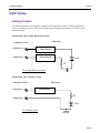
Power Supply
Class I, Div. 1 Battery Charger / Power Supply
The Class I, Div. 1 battery charger and power supply is designed to charge a 12 V lead acid battery and
provide the necessary power to operate the Scanner 1131. (Intrinsically Safe, Class I, Div. 1, Groups C and
D, when installed as per APPENDIX A: Drawings)
WARNING
PLEASE HEED THE WARNING LABEL ON THE BATTERY BRACKET. BE SURE TO
REPLACE THE BATTERY IN A NON-HAZARDOUS AREA, OTHERWISE THERE IS A RISK
OF SEVERE PERSONAL INJURY, DEATH, AND SERIOUS PROPERTY DAMAGE.
CAUTION
PLEASE OBSERVE THE CAUTIONARY NOTE ON THE WARNING LABEL OF THE
BATTERY BRACKET. DO NOT SHIP SCANNER WITH BATTERY MODULE STILL INSIDE
THE SCANNER. DOING SO MIGHT RESULT IN DAMAGE TO THE COMPONENTS INSIDE
THE ENCLOSURE.
Warning :
To prevent ignition of a hazardous atmosphere,
Battery must only be changed in an area known
to be non-hazardous
Avertissement :
Afin de prevenir l'inflammation d'atmospheres
dangereuses, ne changer les batterie que dans des
emplacements designesnon dangereux
Caution :
Do Not Ship Scanner With
Battery Module Inside.
Doing So Will Damage Unit.
Certified Gell Cell Batteries :
Sonnenshein:
Dynasty:
Panasonic:
Powersonic:
Concord:
A212/32G
U1-31
LCL12V33P
PS-12330
GPC1234
Page 15
Scanner 1131 Hardware Manual
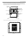
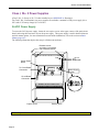
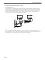
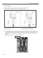
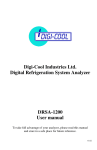
In Class I, Div. 1 instruments, the battery is located behind a cover. To access the battery, loosen the two
captive screws at the corners of the main circuit board and tilt the hinged board forward (towards user). In
the drawing below, the hinged board is shown fully opened and covering the lower portion of the enclosure.
On some enclosures, the hinge is vertical and oriented along the side of the board.
Battery Circuit
Charge Module
(invisible)
Battery Bracket
Solar
Panel
Wiring
Connection
Caution:
Do Not Ship
Scanner With
Battery Module
Inside. Doing
So Will Damage
Unit
Battery (invisible)
Release screws
and swing circuit board
into a horizontal
position.
Circuit Board
Connection
Captive
Screw
Circuit Board
The battery output cable is plugged into a connection on the back of the main circuit board.
Warning:
To prevent ignition of a hazardous atmosphere,
Battery must be changed in an area known
to be non-hazardous
Avertissement:
Afin de prevenir l'inflammation d'atmospheres
dangereuse, ne change pas les batteries que dans des
emplacement designes non dangereux.
Caution:
Do Not Ship Scanner With
Battery Module Inside.
Doing So Will Damage Unit.
Certified Gell Cell Batteries:
Sonnenshein:
Dynasty:
Panasonic:
Powersonic:
Concord:
A212/32G
U1-31
LCL12V33P
PS-12330
GPC1234
Front View
Page 16
1: Installation
July 2010
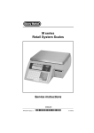
Battery
Positive Terminal
Battery Circuit
Charge Module
Bracket
Velcro
Strap
Back View
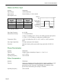
The battery should be charged with a 15-28 Vdc supply at 750 mA maximum. The battery should be
disconnected from the charge control module when not in use. Charge the battery before installing it
into the flow computer. If the battery is fully charged, the battery voltage should be over 13 Vdc 30 minutes
after the power is removed.
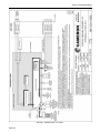
Below is a diagram of the Class I, Div. 1 charge controller / power supply board (Part No. 9A-1131-0301C).
Page 17
Scanner 1131 Hardware Manual
Class I, Div. 2 Power Supplies
(Class I, Div. 2, Groups A, B, C, D when installed as per APPENDIX A: Drawings)
For Class I, Div. 2 instruments, two power supplies are available: a nominal 24-Vdc power supply (19 to
28V) and a 12V battery charger (13 to 28 Vdc).
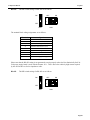
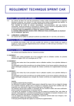
24-VDC Power Supply
To access the 24-Vdc power supply, loosen the two captive screws at the upper corners of the main circuit
board, and swing the board out to access the power supply. This power supply is used in both field mount
and rack mount options; for more information on rack-mount installations, refer to the section on Rack
Mount (page 135).
The following illustration depicts the setup in a field mount enclosure.
Release screws
and swing circuit board
into horizontal position.
Gnd
Power Supply
Board
To Circuit Board
Connection
DC - DC
Converter
Circuit Board
Connection
TERMINAL BLOCK CONNECTORS
Captive Screw
Note:
Page 18
-
+
Backing Plate
In power save mode, the Vtx is turned ON and OFF.
19.2 to
28.8 Vdc
Power Supply
terminal
1: Installation
July 2010
B+
Below is a diagram of the 24-Vdc Class I, Div. 2 power supply board (Part No. 9A-1131-0304C).
12 Volt Battery Charger
The Class I, Div. 2 battery charger / power supply is mounted behind the hinged main board similar to the
Div. 1 charger. The Div. 2 charger has a terminal for connection to the 12 volt lead acid battery and power
for a radio or modem. Below is a diagram of the 12-Vdc Class I, Div. 2 battery charger board (Part No. 9A1131-0302C).
Page 19
Scanner 1131 Hardware Manual
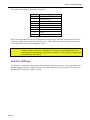
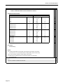
Solar Panel Installation
Mount the solar panel on a post or directly to a south facing flat surface (see chart for angle). The panel
should be mounted high enough to prevent damage or tampering. In locations with heavy snowfall, the
solar panel is often mounted vertically so snow is less likely to accumulate on the solar panel.
Site Latitude
0°
5°-20°
21°-45°
46°-65°
66°-75°
Note:
Optimum Tilt Angle
10°
Latitude + 5°
Latitude + 10°
Latitude + 15°
80°
Angles are marked on the 10-Watt panel; the 5-Watt panel has 10° notches (0°-90° tilt).
Solar Panel Connection
Scanner
(interior)
Solar Panel
(-)
(+)
Battery
Connector
Strain Relief
The battery input (charging) cable has a weatherproof strain relief and a quick-release connector that
connects the battery to the solar panel’s cable.
Page 20
1: Installation
July 2010
Enclosure Options
Scanner 1131C
Scanner 1131C is packaged in a NEMA 4 Fiberglass Reinforced Plastic (FRP) enclosure.
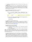
Scanner 1131S
The Scanner 1131S is packaged in a NEMA 4 carbon steel enclosure, as shown below with two DPE+
transducers.
Page 21
Scanner 1131 Hardware Manual
Flashing the Scanner
“Flashing” is the term used to describe the procedure that installs a different version of firmware other than the
one with which the Scanner was shipped. If changing the firmware is NOT necessary, the Startup
Procedure (page 29) may be initiated.
Reprogramming the flash memory of the Scanner 1131 with a new version of firmware requires the use of a
loading program. ScanFlash or WinsLoad, are utilized in a Windows 3.1, 95, 98, XP or NT environment.
Alternatively, if a Windows operating system is not available, ScanLoad is a DOS program that should only be
run in DOS (*NOT* in a DOS shell from within Windows 3.1, 95, etc.).
If you must use ScanLoad, go to page 27 for information about its installation and use.
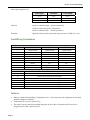
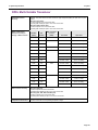
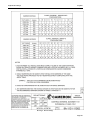
A firmware upgrade is required for all instruments upgraded with a Barton® DPE+ transducer. The table below
shows firmware versions required to support the DPE+ transducer.
Selection Chart for Scanner Firmware
If using this firmware
Install this firmware version
(or later version)
Configure with this software
NFlo version 4.x
NFlo 4.4.0R
ScanWin
NFlo version 3.x
NFlo 3.2.4R
ScanPC
NGas version 3.x
NGas 3.1.4R
ScanPC
NGas version 2.x
NGas 2.7.4R
ScanPC
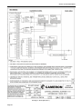
Getting Ready to Flash
The 1131 Flash Memory enables new firmware to be loaded into the Scanner, using the serial port of a PC.
There are no EPROM’s to change.
SW18
(Power Switch)
LCD
Contrast
Switches
Keep pressing
while turning on
SW18.
on
Power
off
Flash erase - PE
NVRAM erase - SB
SW16
(Configuration Lock Switch)
CN19
NVRAM Battery
Backup Jumper
64K
64K
96K
96K
CN27
RAM Low/High Jumper
Jumper position for High RAM
The Flash Erase switch, labeled “PE” for Program Erase, is located at the top right hand corner of the main
board. It is used by the system to initiate the process of re-installing its own firmware. The function is
Page 22
1: Installation
July 2010
sometimes referred to as "Forced Erase." When the switch is pressed and held down while the power is
turned on, the firmware program in the 1131 will be erased.
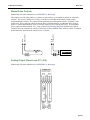
In order to change the firmware installed in flash memory, a PC with the ScanFlash (or WinsLoad, or
ScanLoad) program is required. The PC must be serially linked to the Scanner 1131’s console port.
Console Port
PC
Scanner Cable
Configuration Lock Switch
The optional Configuration Lock Switch (SW16) may be legally required in some locations. When
installed, it is located beside the Power Switch SW18 (see previous diagram). It consists of a locking
hardware hex barstock with a spring and screw assembly affixed above a white switch SW16. When the
screw is tightened or loosened, it engages or disengages the lock with an audible CLICK. To flash or to
superboot the Scanner 1131 RTU, switch SW16 must be in an UNLOCKED state as is shown below:
When it is required to be LOCKED, the screw must be tightened
until a CLICK is heard. Continue tightening the screw until it is
possible to insert the sealing wire through the hex bar
stock/screw. Sealed, it looks like the following:
Page 23
Scanner 1131 Hardware Manual
Start Flashing
IMPORTANT:
Before the Scanner 1131 firmware can be upgraded, you must have the WinsLoad or
ScanLoad software loaded on your laptop in its own directory.
Whether you plan to reprogram the Scanner with either WinsLoad or ScanLoad, carry out the following
common steps, and then go on to the pertinent section.
1. Start ScanWin or ScanPC.
2. Download all History, Configuration and Calibration data. (HIGHLY RECOMMENDED)
3. Exit from ScanWin or ScanPC.
4. “Power down” the Scanner 1131 by moving Power Switch SW18 to the “OFF” position.
5. Be sure the Configuration Lock Switch SW16 (if installed) is in an UNLOCKED state.
6. Continue in the WinsLoad section below or go to page 27 if you are using ScanLoad.
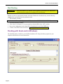
Flashing with ScanLoad (in Windows)
The ScanFlash utility is loaded on your ScanWin installation CD. Simply load the program onto your
computer and follow the on screen instructions
Page 24
1: Installation
July 2010
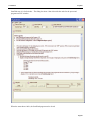
ScanFlash step 4 is Set Switches – The dialog box items 1 thru 4 describe the order for the power and
program erase PE switches.
When the status shows 100%, the ScanFlash program can be closed.
Page 25
Scanner 1131 Hardware Manual
Flashing with WinsLoad (in Windows)
WinsLoad can also be used to flash the Scanner RTU using an MS Windows operating system, but it does
not have a Windows interface like ScanFlash. If you must operate in a DOS environment, go to the section
on Flashing with ScanLoad (DOS) - page 27.
Installing WinsLoad (MS Windows)
1. Obtain the WINSLOAD files from Cameron’s Measurement Systems Division.
2. Open Windows Explorer and create a directory named WINSLOAD on the C: drive of your computer.
3. If the files are unzipped, copy them to C:\WINSLOAD; if the files are zipped, unzip the contents of
WINSLOAD.ZIP into C:\WINSLOAD. The ZIP contains five files including the WINSLOAD
application, two batch files, and two shortcut (PIF) files.
Note:
The shortcuts assume c:\winsload as the default directory - edit their properties if you copy
WINSLOAD and the two batch files elsewhere.
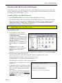
Using WinsLoad
1. Using Windows Explorer, drag the
binary firmware file icon onto the icon
of WINSLOAD1.PIF,
WINSLD1.BAT or WINSLOAD.EXE
if COM1 is the communication port on
your PC. The file may also be dragged
and dropped onto the
WINSLOAD2.PIF or WINSLD2.BAT
icon if COM2 is your communication
port.
Example: In this case, note that
NGN410R.B31 is being dragged and
dropped onto the Winsload1.pif
Shortcut.
Alternatively, you can use the Win95/98/NT command line. For Windows 3.1, you must use the Run
command in the Program Manager menu.
The binary firmware file name will be formatted as follows, depending on the version:
NGXXXXXX.B31 for all NGas versions for the Scanner 1131
NFXXXXXX.B31 for all NFlo versions for the Scanner 1131
IGXXXXXX.B31 for all IGas versions for the Scanner 1131
OPXXXXX.B31 for all OPSat versions for the
Scanner 1131
2. An MS-DOS window is automatically opened.
WinsLoad checks the validity of the binary file
and if it all right, it displays the information
shown here.
3. Now, “power up” the Scanner by depressing
the Flash Erase (PE) button and HOLDING
IT DOWN while you move Switch SW18
back to the “ON” position.
Page 26
1: Installation
July 2010
WinsLoad begins to erase the ROM. When
that is done, it then begins to upload the
new firmware to the Scanner while
displaying the percentage of the file that has
been transferred.
4. When the dialog reports “Transmission
completed.”, close the window.
5. Move Power Switch SW18 to the “OFF”
position.
6. It is HIGHLY RECOMMENDED that the
Scanner RTU be superbooted. To do this,
refer to the section on Startup Procedure
(page 29) for instructions about performing
a superboot.
Flashing with ScanLoad (DOS)
The use of ScanLoad should take place only if you are running in a DOS environment (not from within a
DOS “shell” when running Windows). Use WinsLoad if you are operating in an MS Windows operating
system.
The Getting Ready to Flash section (page 22) should be carried out before using ScanLoad.
Installing ScanLoad Version 2.2
Note:
This procedure must be done in a “Safe Area.”
ScanLoad requires the Scanner software as a binary file with the extension .B31. It is recommended that
ScanLoad be installed onto the hard drive of the operator’s PC. Running ScanLoad from the hard drive
speeds up the downloading process.
To install ScanLoad from disk onto the hard drive perform the following sequence:
1. Turn ON the PC and wait for the C:\ prompt to appear on the screen. If the operator is currently using a
program, exit and return to C:\ prompt.
2. Make a ScanLoad directory by typing after the C:\ prompt:
md Scanload
Page 27
Scanner 1131 Hardware Manual
3. Change the directory by typing after the C:\ prompt:
cd Scanload
4. The following prompt will appear:
C:\SCANLOAD>
5. Copy ScanLoad files EXE., TXT., and binary (B31) from the A drive to the hard drive by typing:
Copy a:*.*
(This will copy all the files that are on the disk, including the binary file) to the ScanLoad directory.
To copy ONLY the ScanLoad files, type the following after the C:\SCANLOAD> prompt:
Copy a: SCANLOAD.*
(This will copy only the ScanLoad.EXE and TXT files from the disk.)
The binary files must then be copied by typing:
Copy a: [binary name]
after the C:\SCANLOAD> prompt. (An example of a binary name is NGS260F.B31).
Using ScanLoad
Before starting ScanLoad, perform the steps outlined in the Getting Ready to Flash section, page 22.
1. From the ScanLoad directory, type: SCANLOAD NGN410R.B31, then press <ENTER>.
SCANLOAD is the executable file that starts the program and NGN410R.B31 is the binary file with the
new firmware. Note that a newer binary file would have a different name.
2. ScanLoad checks that the binary file is a valid one, and informs you that it is ready to download the file.
3. “Power up” the Scanner 1131 RTU by
depressing the Flash Erase (PE) button and
keep HOLDING IT DOWN while you
move Power Switch SW18 back to the
“ON” position. This will start the process
of erasing the old firmware.
ScanLoad will:
•
display a message indicating which
ROM is being erased (if no message is
being displayed at this point see page
29 - Troubleshooting the Flashing
Procedure section of this chapter).
•
start the upload of the new firmware
and display the percentage of the
program that has been transmitted. (If
the percentage is displayed as -1% or, if
any Retries occur, then see the
Troubleshooting
the
Flashing
Procedure section (page 29).
These messages are displayed in the
following manner:
4. As instructed close the window.
5. “Power down” the RTU by moving switch SW18 to the “OFF” position.
6. You are now ready to superboot the Scanner as it is explained in the
Page 28
1: Installation
July 2010
Superbooting the Scanner section (refer to page 31).
Troubleshooting the Flashing Procedure
•
In WinsLoad, abort the flashing process by clicking on the Close button (X). Or, in ScanLoad, press
both the Ctrl and Break keys.
•
Power down the Scanner 1131 as described in Step 4 of the Start Flashing section (page 24).
•
Restart the loading program as explained in Step 1 of Using WinsLoad or Using ScanLoad.
•
Power up the Scanner 1131 as in Step 3 of either Using WinsLoad or Using ScanLoad.
Startup Procedure
Note:
It is very IMPORTANT that the following jumper settings be observed:
CN19 – The NVRAM Battery Backup jumper must be across the pins.
CN27 – The RAM Jumper should be set, for more than three flowruns, to 128K with firmware
4.3.x and above (96K when using earlier firmware versions). Superboot required for
change in jumper position to take effect.
CN16 and CN11 – The PIC1 and PIC2 Jumpers should be across the pins for normal operation.
CN26 - The Display Jumper may be for standard or backlit (if so equipped).
For a Standard display ASM 172050102, p/n 9A-1131-0403C the jumper must be in the
backlit position. (The ASM number is printed on a yellow sticker on the display)
Jumper Settings
Page 29
Scanner 1131 Hardware Manual
Page 30
1: Installation
July 2010
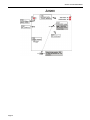
Superbooting the Scanner
Note:
If the Scanner has been FLASHED or is NOT CONFIGURED, perform a Superboot. If it is already
configured, it is not necessary to perform a superboot. Also, note that if a previous configuration
was saved, it is possible to restore a configuration after a Superboot is performed.
After power has been applied to the unit for the first time, it is always recommended to perform a
SUPERBOOT to initialize the memory. This procedure is explained in this section.
Perform a Superboot as follows (refer to the diagram on page 34 for the locations of the switches):
1. Set the Power Switch (SW18) to OFF.
2. Ensure that the Configuration Lock Switch (SW16) is NOT engaged (see page 23).
3. Press the NVRAM Erase (SB) button and keep it held down.
4. Set the Power Switch (SW18) to the ON position while still holding down the NVRAM Erase button
until the display shows:
Superboot found
resetting unit
CAUTION:
**REMINDER**
be sure to setup
unit for
non-superboot
Superbooting causes a
LOSS of Configuration
and History data.
SAVE all Configuration
and History data
BEFORE superbooting
the Scanner RTU.
5. When the display shows the first message (Superboot found…resetting unit), it is safe to release the
NVRAM Erase (SB) button. This will take approximately 10 seconds.
Note:
If the NVRAM Erase button is released before the display shows the “Superboot found…”
message, the unit may not function properly due to an incomplete superboot.
6. Start ScanWin or ScanPC and set the time and date at the prompt.
7. If it is necessary to add new hardware to the Scanner RTU, disconnect or switch off input power to the
Scanner. Proceed to connect the transmitters, RTD’s and other end devices (refer to page 33 - Major
Chips). If the end devices include turbine meters or other pulse output meters connected to A05 and
A06, ensure that SW9 and SW10 are set to the appropriate mode. When you are finished, connect or
turn on input power to the Scanner.
8. Configure the scanner (Refer to the ScanWin manual Chapter 2 – (Overview of the Startup Procedure)
or Section 3.2 – Scanner 1100 Configuration NGas/NFlo X.X.X).
Note:
It is recommended that the new Scanner configuration be rebuilt
in its entirety. Undesired problems may result when a
configuration file built in one firmware version is uploaded to
another Scanner with a different firmware version.
9. Where legally required, the Configuration Lock Switch (SW16) may be
enabled and sealed.
Page 31
Scanner 1131 Hardware Manual
Page 32
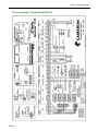
2: Main Board and Wiring
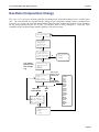
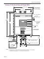
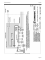
Main Circuit Board’s Major Components
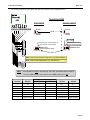
The following diagram outlines the locations of major chips, jumpers and switches.
Major Chips
The preceding diagram shows the major chips as green rectangles bordered by dashed lines.
Page 33
Scanner 1131 Hardware Manual
Jumpers
The preceding diagram shows the locations of jumpers in a pink rectangle bordered by a solid line.
Refer to page 29 for an important note regarding the jumper settings.
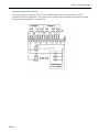
Switches
The Scanner 1131 contains switches for the following:
•
Power (on/off)
•
NVRAM Erase (SB)
•
Flash Erase (PE)
•
VTX to select power to transmitters
•
Analog input configuration
•
Analog out configuration
•
Pulse (frequency) input configuration
•
Serial port configuration
The following diagram shows the relative positions of these switches.
Switches
on
Power
(SW18)
off
LCD
Flash erase- PE
NVRam erase- SB
SW16 - (Configuration Lock Switch)
(SW14)
(SW15) - if installed
(SW12)
Analog
out
(SW8) - if installed
(SW9) (SW10)
(SW7)
Serial Ports
Page 34
(SW11)
Vtx
40
A02
(SW13)
A04
Pulse
Inputs
A05 A06
Analog
Out
A13 A14
48
Analog in
A25
A15
2: Main Board and Wiring
March 2010
Power Switch
The power switch located at the upper left-hand corner (or the front right-hand corner on the 1131 rack
mount) of the main circuit board. To turn the unit off, place the Power Switch in the OFF (down) position.
Switches
on
LCD
Power
off
SW16 - (Meas.
Canada Switch)
Flash erase- PE
NVRAM erase- SB
To turn the unit on, place the Power Switch in the ON (up) position. This causes a Power on restart. The
Power on restart interrupts the flow calculations, but does not affect the configuration or historical data. The
display will show:
Power on restart
The NVRAM Erase Switch
Holding down the NVRAM Erase (SB) button (see Superbooting the Scanner – page 31) effectively
erases all configuration and flow data when the power is turned ON.
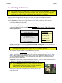
The Flash Erase Switch
The Flash Erase (PE) button is used to erase the firmware program installed on the Scanner. Refer to the
Getting Ready to Flash section on page 22.
Page 35
Scanner 1131 Hardware Manual
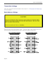
Transmitter Power Supply Switch (to Vtx)
The Transmitter Power Supply Switch, SW11 (located on the main board and detailed below), is comprised
of two banks of switches. The first (named Vtx1 in the diagram below) controls the output to terminal 40 &
43, and the second named Vtx2, controls the voltage to terminal 48 & 51.
When using a 12 Vdc battery charger/power supply (page 121), the transmitter supply output to terminals
40 and 48 is always 10 V, regardless of the switch settings.
If a 24 Vdc isolated power supply (page 124) is installed, the output to the Vtx1 and Vtx2 is switchselectable between 10 V and 24 V, as shown in the diagram.
Note:
See Total Transmitter Supply Output below for more information.
Transmitter Supply
24V
ON
SW11
10V
Vtx1
Vtx2
Boards
Vtx1 Switch
controls
Vtx2 Switch
controls
Six Analog
Vtx1-3
Vtx4-6
Twelve Analog
Vtx1-6
Vtx7-12
Output to
terminal
40 & 43
Output to
terminal
48 & 51
Total Transmitter Supply Output
Vtx10 is defined as the supply output for turbine preamplifiers and inductive proximity sensors.
If 10 V are being produced, the TOTAL transmitter supply output to Vtx1, Vtx2 and Vtx10 is 15 mA.
If 24 V are being developed, the total to these three outputs is 240 mA
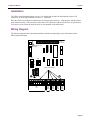
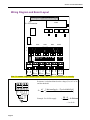
Main Board Wiring Diagrams
See pages 37 (Six Analog Board) and 38 (Twelve Analog in Single-ended Board).
Page 36
2: Main Board and Wiring
March 2010
Six Analog Board
Page 37
Scanner 1131 Hardware Manual
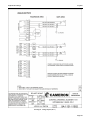
Twelve Analog in Single-Ended Board
Page 38
2: Main Board and Wiring
March 2010
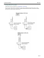
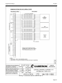
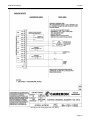
Analog Transmitter Inputs
The Scanner 1131 (10 V, 15 mA) is available with two analog input options.
Six Analog Input Option
Six Differential or Single-ended inputs (see section on Order Code (page 131) for main board options) is
an option that provides the capability to select either differential or single-ended connection of analog
transmitters. It also provides the ability to enable or disable, via DIP switches, the on-board 250Ω precision
load resistors.
Analog in
Analog in
A15
A17 A19
A21
A23 A25
41
44
49
52
Gnd
46
54
Single-ended 4-20 mA
+
com
out
+
+
Low power 1-5 V
Caution: check Transmitter
Supply switch position =10V
Differential 4-20 mA
- shared signal
Analog Input
differrential mode
+
Ground offset 8 V maximum
Note:
The TOTAL +10 V transmitter output (e.g. Vtx10, Vtx1-3 and Vtx4-6) is 15 mA.
Page 39
Scanner 1131 Hardware Manual
Twelve Analog Input Option
This option requires the addition of the 9A-1131-1005-B 250Ω precision resistor pack for use with
conventional 4-20 mA transmitters. The resistor pack is usually located beneath the main board’s terminal
blocks (from about terminal 35 to terminal 58).
Page 40
2: Main Board and Wiring
March 2010
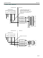
Analog 4-20 mA Transmitter
(Intrinsically Safe when installed as per APPENDIX A: Drawings)
The use of conventional 4-20 mA transmitters requires factory-installed precision load resistors on each
analog channel. Power for the current loop is normally obtained from the Scanner’s internal power supply,
but may also be drawn from an external source.
Page 41
Scanner 1131 Hardware Manual
Analog 1-5 Vdc Transmitter
(Intrinsically Safe when installed as per APPENDIX A: Drawings)
Conventional 1-5 Vdc transmitters do not require load resistors. Power for the circuit is normally obtained
from the Scanner’s internal power supply, but may also be drawn from an external source. This
configuration is intrinsically safe -- Maximum current requirements per I.S.
Low power 1-5 V
Caution: check Transmitter
Supply switch position =10V
Note:
The TOTAL +10V transmitter output (e.g. Vtx10, Vtx1-3 and Vtx4-6) is 15mA.
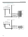
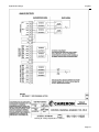
RTD Inputs (Resource A27, A28)
(Intrinsically Safe when installed as per APPENDIX A: Drawings)
Resource A27 and A28 are connected to 100 Ω 3-wire platinum RTD’s as shown. The RTD characteristic
curve is software-selectable for temperature coefficients of either 0.00385 or 0.003902 (Ω/Ω/°) or by
performing a loop calibration at three or more points (refer to Analog and RTD Calibration in Section 2 of
IGas, NGas and NFlo manuals). Platinum 2-wire RTD’s can be used by jumping the lead-line
compensation terminals together as shown:
Note:
Page 42
Shielded wire must be used.
2: Main Board and Wiring
March 2010
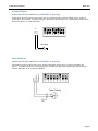
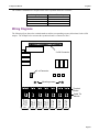
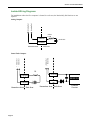
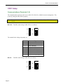
Pulse Inputs (Resources A05, A06)
The Scanner 1131 optional pulse inputs are designed to interface with a wide variety of devices including
variable-reluctance magnetic pickup coils, signals from turbine preamplifiers (both voltage and current
output types), and simple contact closures. DIP switches select the type of signal for each pulse input.
Resources A05 and A06 are pulse inputs. Both switches (SW9 and SW10) are located in the lower middle
of the circuit board (see the diagram on page 34).
With firmware NFlo M4.2.0x and higher, pulse input #1 (A05), was modified to count individual pulses and
increment the count by 1. Previous firmware versions always counted by two; thus, two individual pulses
were required before the pulse count was incremented by 2.
Note:
If the SW9 or SW10 switches are not present, the pulse input option is not installed.
Please refer to chapter 8: System Specifications for the acceptable input signal levels for all the following
types of input devices.
The following chart summarizes the settings and specifications for the 1131 pulse input DIP switches.
Switch #
1
2
3
4
5
6
7
8
ON
Provides VDD, *V to the (+) terminal (for 10 V
power to proximity switches)
6.0 V Threshold (nominal)
Switches are set at 620Ω in a load resistance for
current type preamplifiers
Switches in a filter capacitor for contact
debouncing
First stage preamplifier to comparator
Input signal to comparator (high level inputs)
+Terminal to transformer for low level signal (e.g.
from turbine p/u)
Vtx supply to +terminal for high level devices
such as preamplifiers
OFF
N/A
1.25 V Threshold (nominal)
Regular for voltage type preamplifiers or dry
contacts
Regular (no contact debouncing)
N/A
N/A
Transformer not connected
Vtx not connected to +terminal
1 23 4 56 7 8
ON
+10 VDC supply
Threshold
620Ω load R
Debounce
+24 VDC supply
Transformer
High level signal
Input amplifier
Page 43
Scanner 1131 Hardware Manual
The following diagram illustrates the ON and OFF positions as they are used in the pulse input diagrams:
ON
OFF
Note:
The TOTAL +10 V transmitter output (e.g. Vtx10, Vtx1-3 and Vtx4-6) is 15 mA. See page 36.
2-Wire Preamplifier (818A Current Loop Mode)
(Intrinsically Safe when installed as per APPENDIX A: Drawings)
DANGER:
These configurations are NOT intrinsically safe for the Scanner 1131 unless barriers are
installed.
This mode is suitable for use with the Barton Model 818A preamplifier configured for current-loop output
mode. This preamplifier provides a transmission up to 5 km.
Page 44
2: Main Board and Wiring
March 2010
3-Wire Preamplifier Frequency Input
(Intrinsically Safe when installed as per APPENDIX A: Drawings)
DANGER:
These configurations are NOT intrinsically safe for the Scanner 1131 unless barriers are
installed.
This mode is suitable for use with the Barton 818A preamplifier configured for voltage output with a 0-5
Vdc.
The following illustrates settings for non-Barton preamplifiers:
Page 45
Scanner 1131 Hardware Manual
Magnetic Pickup Coil
(Intrinsically Safe when installed as per APPENDIX A: Drawings)
In this mode, the pulse input is directly connected to a standard variable-reluctance pickup coil that is used
on the Barton turbine meters and other meters of similar design. The input is transformer-coupled to ensure
common-mode noise rejection, and incorporates a variable gain stage to increase the sensitivity to low
frequency and low amplitude signals. Shielded cable, such as Belden 9322, is required.
Proximity Switch
(Intrinsically Safe when installed as per APPENDIX A: Drawings)
In this mode, the pulse is compatible with the BSR (Rockwell) slot sensor or other pulsers that provide a
current output that is signal compatible with the Pepperl & Fuchs #SJ2-N inductive proximity sensor.
Page 46
2: Main Board and Wiring
March 2010
Contact Closure
(Intrinsically Safe when installed as per APPENDIX A: Drawings)
Pulse in Gnd
In this mode, the pulse input is connected to any device that provides a passive contact closure, such as a
reed relay or micro switch. Excitation voltage is provided by the Scanner 1131. Debouncing circuitry limits
the input frequency to 10 Hz maximum.
1
2
3
4
5
6
7
8
Dry Contact
Open Collector
(Intrinsically Safe when installed as per APPENDIX A: Drawings)
This mode provides a generic pulse input, which is compatible with a variety of pulsers and other end
devices. A suitable end device is one that provides a bounce-free solid state output stage, such as an open
collector transistor, or an open-drain MOSFET.
Page 47
Scanner 1131 Hardware Manual
Status Inputs and Status/Pulse Outputs (Resources A7 to A12)
(Intrinsically Safe when installed as per APPENDIX A: Drawings)
The Status Inputs and Status/Pulse Outputs are software configurable.
Status Inputs
(Intrinsically Safe when installed as per APPENDIX A: Drawings)
Status inputs are used to read the state of an external device, which can be either passive (e.g. contact
closure) or active where excitation is from an external source.
Status In.
Gnd
Gnd
Status In.
The type of input is selected by software. When a passive input is selected, an internal power source
attempts to drive a 50 microampere current through the circuit. The voltage through this circuit is limited to
3.2 Vdc. When an active input is selected, the user is provided software selectable voltage thresholds of 2, 7
or 10 Volts. Below the threshold, the input will be false (off); above the threshold, true (on).
Dry contact
+
External source
Passive
Page 48
Active
2: Main Board and Wiring
March 2010
Status/Pulse Outputs
(Intrinsically Safe when installed as per APPENDIX A: Drawings)
Gnd
Status Out
Status Out
Gnd
This output is used for either status (e.g. alarms) or pulse trains (e.g. accumulated volume) as selected by
software. The circuit is suitable for a variety of end devices including small inductive loads such as
electromechanical counters. The output circuit has limited protection against inductive “kickback” from
such devices, but by strapping a diode across the load, as illustrated below, an additional safety factor is
gained. Current requirements in excess of 100 mA require the use of interposing relays. The transmitter
power supply (terminals marked “Vtx”; refer to Main Board Wiring Diagrams) should not be used for
excitation since the computer can switch off the power to these terminals under software control. Excitation
should instead be drawn from an external source, as shown:
00000123
RL
+
+
Analog Output (Resources A13, A14)
(Intrinsically Safe when installed as per APPENDIX A: Drawings)
Page 49
Scanner 1131 Hardware Manual
Console Serial Port (Resource A01)
(Non-Intrinsically Safe)
5
4
3
2
20
DSR
Rx
Tx
Gnd
DSR
Rx
Tx
Gnd
The console port is accessed through the socket on the front panel of the instrument. Shared access to the
serial port A01 is available on optional terminal strips CN2 (Remote Console Accessory Board) or CN3 (a
Remote Console Communication Board). This port is used with a console device only. Shared access can
be set up with either a Remote Console Accessory Board or a Remote Console Communication Board
which are typically used with a Remote Calibration Unit (RCU).
AT
7
3
2
PC,
PC/XT
If the Scanner Measurement RTU is installed in a safe area, an RCU can be located in a hazardous area,
close to transmitters. The RCU enables communication with the Scanner so that loop calibration routine can
be performed. The RCU can have either one or two local console connectors.
Page 50
2: Main Board and Wiring
March 2010
The following diagram illustrates an RCU with two connections.
Safe
Area
Hazardous
Area
DP
RCU
Mainboard
P
T
PC
1131
Termination
RCU Wiring
Scanner
1
3
Rx
D
4
DS
R
The terminal numbers
refer to the CN2
Remote Serial Port
Expansion Board.
Scanner
2
RxD
1
5
TxD
RCU
Termination DSR
2
6
3
7
GND
4
8
Note:
1G 2
ND Tx
D
The user may also use the CN3 Communications Accessory Board or the second serial port of the
main board if the port is assigned to a remote console.
Page 51
Scanner 1131 Hardware Manual
Auxiliary Serial Port (Resources A02, A03 and A04)
(Intrinsically Safe when installed as per APPENDIX A: Drawings)
The auxiliary serial ports A02, A03 and A04 support full RS232C hardware (handshaking signals standard).
Ports A02 and A04 also optionally support RS-422 and RS-485 communications (user selectable).
Port 2 (A02)
Located on main board (terminal strip connections 1-7)
Type:
RS-232C, (optional RS-422, or RS-485)
Signals:
Rx, Tx, RLSD (DCD), RTS, CTS, DTR, and Gnd
Note: “RLSD” is more commonly known as “DCD.”
Port 3 (A03)
Port 4 (A04)
Located on main board (terminal strip connections 8-13)
Type:
RS-232C
Signals:
RX, TX, RTS, CTS, RLSD and Gnd
Located on main board (terminal strip connections 14-19)
Type:
RS-232C (optional RS-422, or RS-485)
Signals:
RX, TX, RTS, CTS, RLSD and Gnd
These ports are used with a modem to provide remote communications (refer to NGas/NFlo 2.X/3.X,
Network Settings). The auxiliary serial ports can also be configured as a second console port (refer to
NGas/NFlo 2.X/3.X, - System Settings).
The switches to select RS232C or RS485/422 for serial ports A02 and A04 are located in the bottom left
corner of the main board. See diagram on page 34.
Page 52
2: Main Board and Wiring
March 2010
The switch positions for serial ports A02 and A04 are shown in the diagrams below.
Serial Port A02
RS485/422 MODE
RS232 MODE
RS232
RS232
SW14
RS422
RS485
RS422
RS485
On - RS485
Off - RS422
asserted DTR - Power always on
actual DTR - Power cycles
RS232 mode,
normal operation shown
RS485 termination 120Ω
resistor (see Note below)
RS485/422 mode
SW7
DCE - Data Communication Equipment (e.g. Modem/Radio)
DTE - Data Terminal Equipment (e.g. Scanner/PC)
Note: * If the Scanner is LAST in the 485 loop, the 120Ω termnation switch should be
left in the "ON" position; place switch in the "OFF" position if it is not.
DCE
Terminal
1
2
3
4
5
6
7
RS232C
Tx
Rx
RTS
CTS
DCD
DTR
Signal Ground
DB25
2
3
4
5
8
20
7
DB9
3
2
7
8
1
4
5
RS-422
Rx+
RxTx+
TxN.C.
N.C.
Signal Ground
RS-485
Sig +
SigN.C.
N.C.
N.C
N.C.
Signal Ground
Page 53
Scanner 1131 Hardware Manual
Serial Port A04
RS485/422 MODE
RS232 MODE
Serial
(Expansion)
RS232
A04
RS232
SW15
RS422
RS485
RS422
RS485
14
On - RS485
Off - RS422
RS485 termination 120Ω
resistor (see Note below)
RS485/422 mode
RS232 mode,
normal operation shown
SW8
Note: * If the Scanner is LAST in the 485 loop, the 120Ω termnation switch should be
left in the "ON" position; place switch in the "OFF" position if it is not.
Terminal
14
15
16
17
18
19
RS232C
Tx
Rx
RTS
CTS
DCD
Signal Ground
RS-422
Rx+
RxTx+
TxN.C.
Signal Ground
RS-485
Sig +
SigN.C.
N.C.
N.C
Signal Ground
MVX-II Wiring for Serial Port A02 or A04
TERMINAL BOARD
RS-485
I-
POWER
Vtx 2
Gnd
+
-
RTD-
RS-485
SCANNER 1131
A
RTD+
B
I+
DGnd
TB1
TB2
Up to two MVX-II instruments can be powered from the Vtx2 (12 Vdc) terminals of the Scanner 1131.
RS-485 +/- terminals for A02 are #1 and #2. RS-485 +/- terminals for A04 are #14 and #15.
Page 54
2: Main Board and Wiring
March 2010
ScanPC Direct Connection
Hazardous Area
7 GND
6 DTR
5 DCD
4 CTS
3 RTS
2 RX
1 TX
Serial Port A02
Safe Area
* If this optional signal is used, set
DCD/CTS to "ON", otherwise
leave it set to "OFF" on the Serial Port
Hardware page. See Section 3.7.8
Serial Ports.
CSA Approved Barrier
12 Vac 1000 ohm
2
3
CSA Approved Barrier
12 Vac 1000 ohm
CSA Approved Barrier
12 Vac 1000 ohm
CSA Approved Barrier
12 Vac 1000 ohm
7
PC
(DTE)
20
DB 25
(female)
Hazardous Area
Safe Area
7 GND
6 DTR
5 DCD
4 CTS
3 RTS
2 RX
1 TX
Serial Port A02
* Optional - See above
CSA Approved Barrier
12 Vac 1000 ohm
CSA Approved Barrier
12 Vac 1000 ohm
CSA Approved Barrier
12 Vac 1000 ohm
CSA Approved Barrier
12 Vac 1000 ohm
2
3
4
5
PC
(DTE)
DB 9
(female)
Page 55
Scanner 1131 Hardware Manual
ScanPC Modem Connection
Hazardous Area
Safe Area
7 GND
6 DTR
5 DCD
4 CTS
3 RTS
2 RX
1 TX
Serial Port A02
DCD/CTS must be set
"ON". Please see
Section 3.7.8 - Serial
Ports
CSA Approved Barrier
12 Vac 1000 ohm
8
CSA Approved Barrier
12 Vac 1000 ohm
CSA Approved Barrier
12 Vac 1000 ohm
Modem
(DCE)
7
3
2
CSA Approved Barrier
12 Vac 1000 ohm
DB 25
(male)
Hazardous Area
Safe Area
7 GND
6 DTR
5 DCD
4 CTS
3 RTS
2 RX
1 TX
Serial Port A02
CSA Approved Barrier
12 Vac 1000 ohm
CSA Approved Barrier
12 Vac 1000 ohm
CSA Approved Barrier
12 Vac 1000 ohm
CSA Approved Barrier
12 Vac 1000 ohm
DCD/CTS must be set to "ON".
See Section 3.7.8 - Serial Ports
Page 56
5
3
2
1
DB 9
(male)
Modem
(DCE)
2: Main Board and Wiring
March 2010
ScanPol / ScanOp Direct Connection
Hazardous Area
Safe Area
7 GND
6 DTR
5 DCD
4 CTS
3 RTS
2 RX
1 TX
Serial Port A02
CSA Approved Barrier
12 Vac 1000 ohm
CSA Approved Barrier
12 Vac 1000 ohm
CSA Approved Barrier
12 Vac 1000 ohm
2
3
7
PC
(DTE)
DB 25
(female)
Hazardous Area
Safe Area
7 GND
6 DTR
5 DCD
4 CTS
3 RTS
2 RX
1 TX
Serial Port A02
CSA Approved Barrier
12 Vac 1000 ohm
CSA Approved Barrier
12 Vac 1000 ohm
CSA Approved Barrier
12 Vac 1000 ohm
2
3
5
PC
(DTE)
DB 9
(female)
Page 57
Scanner 1131 Hardware Manual
ScanPol / ScanOp Modem Connection
Hazardous Area
Safe Area
7 GND
6 DTR
5 DCD
4 CTS
3 RTS
2 RX
1 TX
Serial Port A02
CSA Approved Barrier
12 Vac 1000 ohm
CSA Approved Barrier
12 Vac 1000 ohm
CSA Approved Barrier
12 Vac 1000 ohm
Modem
(DCE)
7
3
2
DB 25
(male)
Hazardous Area
Safe Area
7 GND
6 DTR
5 DCD
4 CTS
3 RTS
2 RX
1 TX
Serial Port A02
CSA Approved Barrier
12 Vac 1000 ohm
5
CSA Approved Barrier
12 Vac 1000 ohm
3
2
Modem
(DCE)
CSA Approved Barrier
12 Vac 1000 ohm
DB 9
(male)
Page 58
3: Expansion Boards
Expansion Boards
Up to two expansion boards can be added to the Scanner’s main circuit board. The expansion boards are
plugged into the slots (B and C) shown in the following diagram:
AS01 – Up to 3 Analog and 3 status outputs
CA01 – Communications and up to 4 analog outputs
CD01- Communications and up to 4 digital inputs/outputs
DI01 – Up to 5 Digital inputs / outputs or Frequency inputs
EB02 – Ethernet and Bluetooth mounted in slot B
Page 59
Scanner 1131 Hardware Manual
Analog and Status Output (AS01)
Specification
General
CSA certified for intrinsically safe operation in Class 1, Division 1, Group C & D areas (when used with
approved barriers - pluggable terminal blocks). The ASO1 Expansion Board is only used on the right-hand
side with expansion Slot C, on main boards with Revision Level 6 and less. This board also offers
automatic test support.
Analog Outputs
Number of Channels
3 (maximum)
Type
Optically isolated, externally powered
Signal Type
4-20 mA current loop, externally powered
Supply Voltage
Minimum <+10 Vdc (liftoff voltage)
Maximum +40 Vdc, across terminals
Accuracy
± 0.1% F.S. error at 25°C (75°F)
D/A Resolution
2 bits
Temperature Effect
± 1% F.S. maximum error over operating temperature range
Calibration
Zero and Full-scale software calibration
Setting Time
<1 second width ±0.1% of F.S. for a 10% step change
Surge Protection
Optically isolated, polarity protected, and surge protected to 500 W for 1
msec.
Allocation
User-selectable
Status/Pulse Outputs
Number of Outputs
3 (maximum)
Type
Optically isolated
Count Rate (Pulse Mode)
0 to 8 Hz, 50 % duty cycle maximum
Max On-State Current
100 mA (fused at TBD mA)
Max On-State Resistance
30 Ω typical at 25°C (75°F)
50 Ω maximum at 25°C (75°F)
Max Off-State Voltage
40 Vdc
Max Off-State Leakage
100 μA over temperature
Surge Protection
Optically isolated, polarity protected, and surge protected to 500 W for 1
msec.
Typical Usage
Status Mode:
Pulse Mode:
Accumulating Count Output (volume, mass, energy, etc.)
Allocation
User-selectable
Page 60
Alarms
3: Expansion Boards
July 2010
The available combinations of outputs on the ASO1 expansion board are as follows:
Analog Outputs
3
1 (Resource 04)
0
3
Status / Pulse Outputs
3
1 (Resource 01)
3
0
Wiring Diagrams
The following figure shows the terminal numbers and the corresponding resource allocations for the ASO1
outputs. The example below assumes the expansion board is connected to Slot C.
2 x 28 Connector
.
2 x4 Connector
Mounting screws
1
2
3
4
5
6
7
8
9
10
11
12 13
14 15
Terminal
Blocks
Transmitter
Supply
Outputs
Status
Pulse
Output
Status
Pulse
Output
Status
Pulse
Output
Analog
Output
Analog
Output
Analog
Output
Cable Tie
Mounts
"Vtx"
C01
C02
C03
C04
C05
C06
Page 61
Scanner 1131 Hardware Manual
Isolated Wiring Diagrams
For installations where the flow computer is located in a safe area, the Intrinsically Safe barriers are not
required.
-Analog Out
+Analog Out
Analog Outputs:
250 Ω
Load
I.S. Barrier
+10-40 Vdc
I.S. Barrier
Hazardous Area
Safe Area
+ Status Out
- Status Out
- Status Out
+ Status Out
Status/ Pulse Outputs:
RL
I.S. Barrier
I.S. Barrier
00000123
I.S. Barrier
Hazardous Area
Page 62
I.S. Barrier
+
Safe Area
Hazardous Area
+
Safe Area
External
Counter
3: Expansion Boards
July 2010
Non-Isolated Wiring Diagrams
The DC power supply (24 Vdc nominal) should be used when powering outputs from the “Vtx” terminals.
The Intrinsically Safe battery power supply is not designed to power analog outputs.
Analog Outputs:
Analog Outputs
+ - + - + -
Vtx
(10-30 Vdc)
Analog Outputs
+ - + - + -
Vtx
(10-30 Vdc)
250 Ω
Load
250 Ω
Load
Signal "Gnd"
Main Board
Signal "Gnd"
Main Board
Status / Pulse Outputs:
Vtx
Status/Pulse
Outputs
+ - + - + -
Vtx
Status/Pulse
Outputs
+ - + - + -
Load
Load
Signal "Gnd"
Main Board
Signal "Gnd"
Main Board
Page 63
Scanner 1131 Hardware Manual
Communications and Analog Output (CAO1)
The Communications / Analog Output expansion board available for the Scanner 1131 Flow Computer offers
several different configurations of asynchronous serial communications and 0 to 4 isolated analog channels.
Note:
This serial communications port is not recommended for ScanCom networks.
This board is no longer manufactured
Specifications
General
Operating Temperature
-40°C to +60°C (-40°F to 140°F)
Storage Temperature
-55°C to +85°C (-67°F to 185°F)
Relative Humidity
0 to 95 % RH non-condensing
Certification
Individual circuits CSA approved for Intrinsically Safe operation in Class
1, Division 1, Group C & D areas when used with appropriate barriers.
Serial Communications
Quantity
One
Interface
Switch selectable as RS-232C, RS-422, or RS-485
Available Signals
RS-232C: Rx, Tx, RTS, CTS, DCD, and DTR
RS-485:
Signal+, Signal-
RS-422:
Tx+, Tx-, Rx+, Rx-
Baud Rates
110, 150, 300, 600, 1200, 2400, 4800, or 9600 baud, software selectable
Parity
Even, odd, or none, software selectable
Stop Bits
1 or 2, software selectable
Function
Printer, remote console, or gas chromatograph port
Protection
Surges to 300 W @ 1 msec. plus DC overload to ±40 V
Page 64
3: Expansion Boards
July 2010
Analog Outputs
Quantity
Four
Type
Optically isolated, externally powered
Accuracy
± 0.1 % of FS max. error @ 25°C (75°F) (after factory calibration)
Temperature Effect
± 1.0 % of FS maximum error over temperature
Liftoff Voltage
< + 10.0 Vdc
Maximum Voltage
± 40 Vdc
D/A Resolution
12 Bits
Calibration
Zero and Full-scale software calibration
Setting Time
< 10 msec. to 0.1 % of full-scale for a 10 % step change
Function
User assignable (Flow rate, temperature, etc.)
Field Wiring Termination
Terminal
1
2
3
4
5
6
7
8
9
RS232C
Signal Ground
Tx
Rx
RTS
CTS
DTR
DCD
Signal Ground
Transmitter Supply
RS-422
Signal Ground
Rx+
RxTx+
N.C.
TxN.C.
Signal Ground
Transmitter Supply
RS-485
Signal Ground
Sig +
SigN.C.
N.C.
N.C.
N.C
Signal Ground
Transmitter Supply
Options
•
Industry Canada Switch Stuffing (Configuration Lock) - Once locked, the port assignment for this board
cannot be changed accidentally
•
Uninterrupted Vtx (to a low power relay)
•
The remote console expansion board that plugs into the lower pins of expansion slot B can also be
plugged into the CAO1 expansion board.
Installation
The expansion board mounts over the 1131 main board either on the left side resource ‘B’ connectors, or on
the right side resource ‘C’ connectors.
Place the CAO1 card so that the terminal strips are facing down toward you. Align the pins and sockets
located on the expansion board and the main board; then push down firmly. Ensure that the sockets fully
cover all the pins and are not offset by one pin location. Two captive screws fasten to the board securely to
two standoffs on the main board.
Page 65
Scanner 1131 Hardware Manual
Wiring Diagrams
The following figure shows the terminal numbers and the corresponding resource allocations for the CAO1
outputs:
.
ID #
ASSM #
2x28 Connector
Configuration Lock (CCAC)
Off
On
1
2
SW2
SW1
2x6 Connector
Page 66
12 13
14 15
16 17
+ -
+ -
+
+
Analog
Output
Analog
Output
B01
C01
10 11
Analog
Output
1 2 3 4 5 6 7 8 9
Analog Output Blocks
Analog
Output
Wiring Terminal Block
B02
C02
B03
C03
B04
C04
B05
C05
-
-
3: Expansion Boards
July 2010
CAO1 Setup
Analog Outputs
The analog output ports are designed to manipulate an external power source of proper magnitude to
achieve a 4 to 20 mA current. The correct wiring method for analog output ports on a CAO1 board is
illustrated bellow:
Intrinsically Safe Ground Referenced Load:
Safe Area
Hazardous Area
Analog Out +
Send Barrier
Analog Out -
Return Barrier
+24V
RL
I.S. Ground Referenced Load
Intrinsically Safe “Floating” Load:
Hazardous Area
Analog Out +
Analog Out -
Safe Area
Send Barrier
RL
+24V
I.S. 'Floating' Load
Page 67
Scanner 1131 Hardware Manual
Non-Intrinsically Safe Ground Referenced Load:
Analog Out +
Analog Out Transmitter Supply
RL
Ground
Non-I.S. Ground Referenced Load
Communications
The serial port can be configured to an RS-232C, RS-422, or RS-485 electrical configuration. This is done
by setting the DIP switches.
RS-232C: The DIP switch settings for RS-232C are as follows:
OFF
ON
1
2
OFF
SW1
SW2
The terminal block wiring assignments are:
Terminal
1
2
3
4
5
6
7
8
9
Page 68
Signal
Ground
Transmit Data (Tx)
Receive Data (Rx)
Ready to Send (RTS)
Clear to Send (CTS)
Data Terminal Ready (DTR)
Data Carrier Detect (DCD)
Ground
Transmitter Voltage Supply
ON
3: Expansion Boards
RS-422:
July 2010
The DIP switch settings for RS-422 are as follows:
ON
OFF
ON
1
2
OFF
SW1
SW2
The terminal block wiring assignments are as follows:
Terminals
1
2
3
4
5
6
7
8
9
Signal
Ground
Receive Data Positive (Rx+)
Receive Data Negative (Rx-)
Transmit Data Positive (Tx+)
Do Not Connect
Transmit Data Negative (Tx-)
Do Not Connect
Ground
Transmitter Supply Voltage (Vtx)
Please note that the RS-422 setting is not guaranteed to work properly unless the Non-Intrinsically Safe 24Volt power supply board is used with the Scanner 1131. This is due to the relatively high current required
by the 422 line drivers for low impedance cable.
RS-485:
The DIP switch settings for RS-485 are as follows:
ON
OFF
ON
1
2
OFF
SW1
SW2
Page 69
Scanner 1131 Hardware Manual
The terminal block wiring assignments are as follows:
Terminal
1
2
3
4
5
6
7
8
9
Signal
Ground
Data Positive (Sig+)
Data Negative (Sig-)
Do Not Connect
Do Not Connect
Do Not Connect
Do Not Connect
Ground
Transmitter Supply Voltage (Vtx)
Please note that the RS-485 setting is not guaranteed to work properly unless the Non-Intrinsically Safe 24Volt power supply board is used with the Scanner 1131. This is due to the relatively high current required
by the RS-485 line drivers for low impedance cables.
Wiring Note: If this expansion board is located at one end of the two-wire RS-485 cable, then the switch
settings, as shown, can be used. Should the CAO1 be located at a midpoint connection,
then the 100Ω line termination resistor must be switched out. This is done by setting switch
2 on SW2 to the OFF position.
Scanner Settings
The Scanner 1131 hardware settings are the same as the two main board serial ports. Since the RS-422 and
RS-485 settings do not offer terminals for Data Carrier Detect (DCD) and Clear to Send (CTS), make sure
that the DCD/CTS hardware setting is set OFF.
Page 70
3: Expansion Boards
July 2010
Communications and Status (Digital) Input/Output (CDO1)
The 1131 CDO1 expansion board provides a single communication port (configurable as either RS-232, RS485, or RS-422) as well as four digital channels which can be configured as either status inputs, status outputs,
or pulse outputs.
Note:
Use the Modbus protocol only on this port. Do not use ScanCom.
Specifications
General
Operating Temperature
-40°C to +60°C (-40°F to +140°F)
Storage Temperature
-55°C to +85°C (-67°F to +185°F)
Relative Humidity
0 to 95% RH non-condensing
Certifications
Individual circuits CSA approved for intrinsically safe operation in Class 1,
Division 1 Group D areas when used with appropriate barriers.
Serial Communications
Quantity
One
Interface
Switch selectable as RS-232C, RS-422, or RS-485
Available Signals
RS-232C: Rx, Tx, RTS, CTS, DCD, and DTR
RS-422:
Tx+, Tx-, Rx+, and Rx-
RS-485:
Signal+, Signal-
Baud Rates
110, 150, 300, 600, 1200, 2400, 4800, or 9600 baud, software selectable
Parity
Even, odd, or none, software selectable
Stop Bits
1 or 2, software selectable
Function
Printer, remote console, or gas chromatograph port
Protection
Surges to 500 W at 1 msec. plus DC overload to ±40 V
Status Inputs and Status/Pulse Outputs
Quantity
Four
Input Voltage
+40 Vdc maximum
On-State Current
100 mA Maximum (status or pulse output)
On-State Resistance
20 Ω typical at 25°C (75°F) (status or pulse output)
25 Ω maximum at 25°C (75°) (status or pulse output)
Maximum Pulse Rate
8 counts/second at 50% duty cycle (pulse output)
Off-state Leakage
<100 μA at +40 V (status input, jumper removed)
<2000 μA at +40 V (status input, jumper installed)
Page 71
Scanner 1131 Hardware Manual
Status Inputs Signal Levels
Maximum Low
Level Signal
2.0 V
5.0 V
8.0 V
Function
Nominal
Threshold
3.0 V
7.0 V
10.0 V
Minimum High
Level Signal
4.0 V
9.0 V
12.0 V
Alarm or controller output (status output mode)
Totalized count output (pulse output mode)
Alarm or controller input
Protection
(status input mode)
Optically isolated, polarity protected, surge protected to 500W for 1 msec.
Field Wiring Termination
Terminal
1
2
3
4
5
6
7
8
9
10
11
12
13
14
15
16
17
Serial Interface Termination
RS-232C
RS-485
RS-422
Signal Ground
Signal Ground
Signal Ground
TX
SIG+
RX+
RX
SIGRXRTS
N.C.
TX+
CTS
N.C.
N.C.
DTR
N.C.
TXRLSD
N.C.
N.C.
Signal Ground
Signal Ground
Signal Ground
Transmitter Supply
Transmitter Supply
Transmitter Supply
I/O Signal Description
Status In/Status Out/Pulse out #1 signal+
Status In/Status Out/Pulse Out #1 signalStatus In/Status Out/Pulse Out #2 signal+
Status In/Status Out/Pulse Out #2 signalStatus In/Status Out/Pulse Out #3 signal+
Status In/Status Out/Pulse Out #3 signalStatus In/Status Out/Pulse Out #4 signal+
Status In/Status Out/Pulse Out #4 signal-
Options
•
Industry Canada Switch Stuffing (Configuration Lock). Once locked, the port assignment for this board
cannot be changed accidentally
•
Uninterrupted Vtx (to a low power relay)
•
The remote console expansion board that plugs into the lower pins of expansion slot B can also be
plugged into the CD01 expansion board.
Page 72
3: Expansion Boards
July 2010
Installation
The CD01 expansion board mounts over the 1131 main board on either the left-hand side resource “B”
connection, or on the right-hand side resource “C” connectors.
Place the CD01 card so that the terminal strips are facing down toward you. Align the pins with the sockets
and push down firmly. Ensure that the sockets fully cover all the pins and are not offset by one pin location.
Two captive screws fasten the board securely to two standoffs on the main board.
Wiring Diagram
The following diagram shows the terminal numbers and the corresponding resource allocations for the
CD01 inputs and outputs.
2x28
Connector
Configuration Lock
(CCSA)
SW2
SW1
1
ON
2
ON
OFF
OFF
Wiring Terminal Blocks
2x6
Connector
1
2
3
4
5
B01
C01
6
7
8
9
10 11
12 13
14 15
16 17
Status
In/Out
Pulse
Out #1
Status
In/Out
Pulse
Out #2
Status
In/Out
Pulse
Out #3
Status
In/Out
Pulse
Out #4
Page 73
Scanner 1131 Hardware Manual
CDO1 Setup
Communications (Terminals 1-9)
The communications serial port can be set to an RS-232C, RS-422, or RS485 electrical configuration. This
is done by setting the DIP switches properly.
Note:
It is not recommended that the ScanCom protocol be used with this serial port. Use Modbus
instead.
RS-232C: The DIP switch settings for RS-232C are as follows:
1
ON
2
ON
OFF
OFF
SW2
SW1
The terminal block wiring assignments are:
Terminal
1
2
3
4
5
6
7
8
9
RS-422:
Signal
Ground
Transmit Data (Tx)
Receive Data (Rx)
Ready to Send (RTS)
Clear to Sent (CTS)
Data Terminal Ready (DTR)
Data Carrier Detect (DCD)
Ground
Transmitter Voltage Supply (Vtx)
The DIP switch settings for RS-422 are as follows:
1
ON
2
ON
OFF
OFF
SW2
Page 74
SW1
3: Expansion Boards
July 2010
The terminal block wiring assignments are:
Terminal
1
2
3
4
5
6
7
8
9
Signal
Ground
Receive Data Positive (Rx+)
Receive Data Negative (Rx)
Transmit Data Positive (Tx+)
Do Not Connect
Transmit Data Negative (Tx-)
Do Not Connect
Ground
Transmitter Supply Voltage (Vtx)
Please note that the RS-422 setting is not guaranteed to work properly unless the Non-Intrinsically Safe 24Volt power supply board is used with the Scanner 1131. This is due to the relatively high current required
by the 422 line drivers for low impedance cables.
RS-485:
The DIP switch settings for RS-485 are as follows:
1
ON
2
ON
OFF
OFF
SW2
SW1
The terminal block wiring assignments are:
Terminal
1
2
3
4
5
6
7
8
9
Signal
Ground
Data Positive
Data Negative
Do Not Connect
Do Not Connect
Do Not Connect
Do Not Connect
Ground
Transmitter Supply Voltage (Vtx)
Wiring Note:
If this expansion board is located at one end of the two
wire RS-485 cable, then the switch settings can be used
as shown. Should the CD01 be located at a midpoint
connection, then the 100Ω line termination resistor must
be switched out. This is done by setting switch 2 on SW1
to the OFF position.
Please note that the RS-485 setting is not guaranteed to work properly unless the Non-Intrinsically Safe 24Volt power supply is used with the Scanner 1131. This is due to the relatively high current required by the
RS-485 line drivers for low impedance cables.
Page 75
Scanner 1131 Hardware Manual
Digital I/O Circuits (Terminals 10-17)
The following table shows the field termination for the four digital I/O circuits:
Terminal
10
11
12
13
14
15
16
17
Signal Description
Status In/Status Out/ Pulse Out #1 signal +
Status In/Status Out/Pulse Out #1 signal Status In/Status Out/Pulse Out #2 signal +
Status In/Status Out/Pulse Out #2 signal Status In/Status Out/Pulse Out #3 signal +
Status In/Status Out/Pulse Out #3 signal Status In/Status Out/Pulse Out #4 signal +
Status In/Status Out/Pulse Out #4 signal -
+
17 SI/O-
16 SI/O+
15 SI/O-
14 SI/O+
13 SI/O-
12 SI/O+
11 SI/O-
10 SI/O+
Except for one difference, the digital I/O channels function identically and have the same specifications as
the status inputs/outputs on the main board. See pages 48, 49 and 127. The one difference is that the digital
I/O channels are individually isolated from the communications terminal block (resources 1-9), as well as
from each other, to allow them to be treated as separate intrinsically safe circuits. This allows all of the
circuits to be connected to safe area equipment without running into energy limitations imposed by multiple
barrier outputs. However, adequate physical segregation of the field wiring must be made so that the wiring
faults will not be considered in the I.S. analysis.
Output
RL
+
Input
RL
+
Input
RL
Scanner Settings
The Scanner 1131 hardware settings are the same as the two main board serial ports. Since the RS-422 and
RS-485 settings do not offer terminals for Data Carrier Detect (DCD) and Clear to Send (CTS), make sure
that the DCD/CTS hardware setting is set to OFF.
Page 76
3: Expansion Boards
July 2010
Status I/O, Pulse I/O Digital Channels (DIO1)
The 1131 DIO1 expansion board provides up to five digital channels that can individually be configured as
either status inputs, pulse inputs, status outputs, or pulse outputs. Options that must be specified at time of
ordering include:
•
2 or 5 channels
•
Standard accuracy for accumulating pulses inputs from turbine/ PD meters or high accuracy for use with the
high frequency output from a densitometer
•
With or without phase discrimination / pulse comparator (Level B Security as per IP 252/76)
Each channel is independently optically isolated, and is designed to be Intrinsically Safe for operation in Class I,
Division 1, Group D areas when used with appropriate barriers. Each channel and the circuitry it uses are
configured through two sets of DIP switches. SW1 through SW5 (see board layout diagram) are used to set the
threshold voltage for each corresponding channel (SW1 is used for channel 1; SW2 is used for channel 2, etc.).
SW6 through SW10 are used to set the mode for each channel (SW6 is used for channel 1; SW7 is used for
channel 2, etc.).
When optionally supplied with the phase discrimination / pulse comparator circuitry, channels 2 and 4 are
individually configured to serve as pulse comparators for the sequence of pulses on channels 1 vs. 2 and 3 vs.4.
Monitoring provides continuous comparison of number, frequency, phase, and sequence of the two trains of
pulses. At the same time, interfering pulses are also detected and a low frequency cutoff feature eliminates false
error detection during flow startup and shutdown.
As a function of this same pulse comparator circuitry, channels 2 and 4 can provide phase discrimination to
detect flow direction with turbine meters that have dual pickup coils.
The digital discriminators can detect pulse trains that are electrically 90° out of phase.
Note:
Due to limitations imposed by the energy of multiple, Intrinsically Safe circuits in a single enclosure,
certification may be limited to operation with one or two circuits only. This limitation is based on the
total number of intrinsically safe circuits, which are connected to the Scanner 1131. (See the I.S.
connection drawings found in Appendix A of this manual).
Specifications
General
Operating Temperature
-40°C to +60°C (-40°F to +140°F)
Storage Temperature
-55°C to +85°C (-67°F to 185°F)
Relative Humidity
0 to 95% RH non-condensing
Certifications
Individual circuits designed for CSA I.S. approval in Class I, Division 1,
Groups C and D areas when used with appropriate barriers.
Page 77
Scanner 1131 Hardware Manual
Status and Pulse Input
Quantity
5 Maximum
Input Voltage
+40 Vdc Maximum
Input Current
Current limited @ 2.5 mA nominal
Input Signal Levels:
Maximum
Low Level
Signal
0.50 V
1.5 V
5.0 V
8.0 V
Nominal
Threshold
1.0 V *
3.0 V
7.0 V
10.0 V
Minimum
High Level
Signal
1.50 V
4.5 V
9.0 V
12.0 V
Maximum
High
40 V
Minimum High
Level Signal
Nominal
Threshold
Maximum Low
Level Signal
0
* Not optically isolated.
Pulse Input Frequency
0 to 10 kHz
Measurement Accuracy
± 1 Count (totalization)
± 0.001 % of reading @ 25°C (75°F) (1 Hz-10Hz) (precision input option)
± 0.1 Hz ± 0.1 % of reading over temperature (standard input)
Temperature Effect
± 0.01% of reading from -40°C to +60°C (-40°F to +140°F) (precision
input)
Pulse Input Update Rate
5 seconds maximum for all channels
Protection
Optically isolated, polarity protected & surge protected to 300 W for 1
msec.
Phase Discriminator
Quantity
2 Maximum
Function
Compares phase relationship of inputs 1 vs. 2 and 3 vs. 4
Phase Accuracy
± 15°C (59°F)
Operating Frequency
1 Hz to 10 kHz
Pulse Comparators
Quantity
2 Maximum
Function
Continuous comparison of two pulse trains for sequence and phase, as well
as detection of simultaneous interfering pulses, with a latched alarm
generated if an error is detected. Programmable low frequency cutoff
prevents false alarms during flow startup or shutdown.
Operating Frequency
1 Hz to 10 kHz
Page 78
3: Expansion Boards
July 2010
Status and Pulse Output Specifications
Input Voltage
+40 Vdc Maximum
On-State Current
100 mA Maximum @ 25°C (75°F)
On-State Resistance
25 ohms Maximum @ 25°C (75°F)
Maximum Pulse Rate
8 pulses/second @ 50 % duty cycle
Off-State Leakage
< 100 μA @ +40 V - 25°C (75°F)
Protection
Optically isolated and surge protected to 300 W for 1 msec.
Installation
The DIO1 board can be installed in either (or both) expansion locations on the 1131 main board. As with all
1131 expansion cards, the system automatically recognizes its presence, as well as the type of card and its
manufacturing configuration. In addition, the remote terminal interface boards (RTI1 and RTI2) can be
plugged in on top of a DIO1 card when installed in the left-hand location (Slot B) to allow parallel access to
the console serial port.
Page 79
Scanner 1131 Hardware Manual
Wiring Diagram and Board Layout
FPGA
2 x 28 Connector
.
SW6
1 2
3 4
SW7
5
SW8
1 2 3 4 5 6
On
1 2
3 4
SW9
5
SW10
1 2 3 4 5 6
1 2
3 4
5
Off
On
SW2
SW3
SW4
SW5
1 2 3 4
1 2 3 4
1 2 3 4
1 2 3 4
SW1
1 2 3 4
Off
B/C 02
9
10
11
Pin +
B/C 03
B/C 04
12
Pin -
8
Pin -
Pin -
B/C 01
7
Pin +
6
Pin -
5
Pin +
4
Pin +
Vtx -
3
Pin -
2
Pin +
1
Vtx +
2 x6 Connector
B/C 05
Note: For contact or open collector inputs, voltage can be applied as shown below or externally:
Resistance is calculated based on the voltage (Vtx, 10V or 24 V)
and the threshold.
4
Pin -
3
Pin +
2
Gnd
Vtx +
1
R=
ΔV ⎛ MinimumSupply − ThresholdMinHigh ⎞
=⎜
⎟
I
MinimumCurrent
⎝
⎠
B/C 01
R
Example: For 24 Vdc supply
=
20 − 9
= 4.4kΩ max .
2.5mA
= 2 to 4 k Ω
Page 80
3: Expansion Boards
July 2010
Circuit Description
I/O Circuit Description
Each of the 5 channels provide an optically isolated input that can be configured to various modes and
threshold voltage levels, depending on the type of the incoming pulses. This conditions the circuit to
interface with external pulse preamplifiers, contact closures, and logic level signals. All 5 channels are
identical, with the exception of channels 2 and 4 which have an additional mode switch to allow for the
detection of positive and/or negative going pulses from many mass flow / density meters.
Each channel has 2 separate blocks of DIP switches used for configuration which can be identified as
follows (also refer to board layout diagram for placement on the circuit board – page 80):
Channel
1
2
3
4
5
Threshold Level Switches
SW1
(4 switch block)
SW2
(4 switch block)
SW3
(4 switch block)
SW4
(4 switch block)
SW5
(4 switch block)
Mode of Operation Switches
SW6
(5 switch block)
SW7
(6 switch block)
SW8
(5 switch block)
SW9
(6 switch block)
SW10
(5 switch block)
Threshold Level Switches (SW1 through SW5)
These switches select the threshold level of the input when used in the optically isolated mode. In the nonisolated mode (input threshold 1.5V), these switches do not affect the performance of the channel in any
way (see section on Mode of Operation Switches (SW6 through SW10)).
Input Threshold
1 2 3 4
ON
1.8 V
2.9 V
7.0 V
10.0 V
ON
OFF
with optical isolator OFF
means switch can
be either ON or OFF
The “OFF” threshold selection is used when the channel is being used in non-isolated mode, as a digital
output channel, or when the channel is not being used at all. Turning it off will conserve the 2 mA per
channel required to power the optic isolator.
Note:
Threshold Switch 1 should ALWAYS be in the same position as Mode Switch 2.
Page 81
Scanner 1131 Hardware Manual
Mode of Operation Switches (SW6 through SW10)
These switches are used to configure the mode of operation of each of the channels. Some of the different
“modes” include:
•
Optically isolated input vs non isolated
•
Routing the input signal through a debounce circuit for eliminating the chatter associated with
mechanical contact closure devices
•
Routing the input signal through the pulse comparator circuit for use with Level B Security or Phase
Discrimination applications
•
Routing the input signal through BOTH the input isolator and the pulse comparator
Switch
1
2
ON
Pulse input is “debounced”
Max frequency is 10 Hz.
Optical isolation ON
3
Connects the +ve input of the signal to the pulse
comparator
4
Connects the -ve input of the signal to the pulse
comparator
5
Output of optical isolator is connected to the
pulse comparator (i.e. Switch 2 ON and pulse
comparator is required)
Sets the polarity of the threshold
For the detection of –ve going Pulses (i.e.
Threshold= -1.0 V) when in non-isolated mode
(Switch 2 OFF)
6
(Channels 2
and 4 only)
OFF
Pulse input is full bandwidth
Max frequency is 10 kHz.
Optical isolation OFF for use as a Non-isolated
input or as a pulse / digital output
Disconnects the +ve input from the Main circuit,
forcing the use of Optical isolation (i.e. Switch 2
ON)
Disconnects the -ve input from the Main circuit,
forcing the use of Optical isolation (i.e. Switch 2
ON)
Output of isolator is disconnected from the pulse
comparator (i.e. Switch 2 OFF or pulse
comparator is not required)
Sets the polarity of the threshold
For the detection of +ve going Pulses (i.e.
Threshold= +1.0 V) when in non-isolated mode
(Switch 2 OFF)
NOTES: Switches 2 and 5 will ALWAYS be in the same relative position and in the opposite position to Switches 3
and 4. (i.e. 2 and 5 ON with 3 and 4 OFF or 2 and 5 OFF with 3 and 4 ON)
Switch 6 is ALWAYS in the OFF position except when used with densitometer applications.
Page 82
3: Expansion Boards
July 2010
Phase Discriminator and Level B Pulse Security
Note:
Phase Discrimination and Level B security are only available on version 2.x and 3.x firmware with
ScanPC user interface. They are not available on version 4.x firmware with ScanWin user interface.
Channels 1 / 2 and 3 / 4 can be used for Phase discrimination and Level B Security. To facilitate this
application, the inputs must be used in pairs (i.e. channel 1 would measure one pulse stream from a meter
and compare the signal to channel 2 measuring the second pulse stream from that same meter. Similarly,
channels 3 and 4 are used together).
When the pulse comparator is enabled through the Mode of Operation Switches as detailed in the previous
section, Mode of Operation Switches (SW6 through SW10), a unique hardware type is created in the
Scanner application firmware that differs from a normal pulse input hardware resource. This unique
hardware type is called a Pulse In LB/PD (Level B / Phase Discrimination) and it has some additional
attributes that are not available in a standard pulse input hardware resource. The additional attributes are as
follows:
Attribute
LB Cutoff:
Units
Hz
Phase=
Degrees
LB Alarm…
N/A
Description
A user entered “Level B” low frequency cutoff, which prevents alarms from being
flagged during start-up or shutdown.
A live input indicating the phase shift between the two pulse streams being compared.
Note that the sign (+/-) indicates whether the shift is leading or lagging.
The latched alarm state of the “Level B” alarm (either ON or OFF). To reset or
acknowledge the alarm, press PAGE DOWN and follow the instructions
1131 Phase Discrimination Configuration Procedure
To configure the 1131 for Phase Discrimination:
1. Install DIO1 board into either Slot B or Slot C.
2. Superboot the Scanner (page 31).
3. Create a flowrun named FORWARD. Configure it so that
•
Primary Device > Volume Pulse Meter
•
Device Type > “Standard” (“Level B” if level is required)
•
Flow Direction > Forward
4. Create another flowrun named REVERSE. Configure it so that
•
Primary Device > Volume Pulse Meter
•
Device Type > “Standard” (“Level B” if level is required)
•
Flow Direction > Reverse
5. From the Hardware page, assign Resource CO1 as a Pulse in LB/PD. Resource Co2 will automatically
switch to a pulse-in when CO1 is assigned for phase discrimination.
6. Assign resources in the Forward flowrun (Qf (uncorrected rate) is assigned to resource CO1; the rest of
the variables are assigned accordingly).
7. Assign resources in the Reverse flowrun (Qf (uncorrected rate) is assigned to resource CO1; the rest of
the variables are assigned as in the Forward flowrun).
Note:
If KFactor is the same in BOTH directions, assign to CO1; if KFactor is different, then assign
to CO2 resource.
Page 83
Scanner 1131 Hardware Manual
8. Set DIP switch settings as indicated in the manual.
Level B Pulse Security
Level B Security, in accordance with the Institute of Petroleum IP252/76, requires:
“Continuous monitoring, error indication and alarm signaling by methods of comparison...This level of
security is intended to give warning of transients and other spurious (artificial) influences, supply borne and
radiated, in addition to functional errors and failures.”
Further stated under the Level B Block Diagram:
“The diagram illustrates a dual transmission system with a dual pulse comparator in which the pulse trains
are continuously monitored for number, frequency, phase, and sequence, and any irregularities indicated.
Simultaneous interfering pulses must be detected and indicated. An alarm is given if pulses are lost or
gained on either channel.”
This security is generally used on custody transfer liquid metering applications to detect missing rotor
blades on a turbine meter. When an error is detected, the application software in the Scanner latches the
“LB Alarm” (Level B) at the pulse input hardware level. The alarm must be acknowledged manually to
clear the alarm- this is accomplished by pressing the PAGE DOWN key from the LB Alarm in the hardware
page for the pulse input.
Phase Discrimination
When connected to a dual pick-up turbine meter, where the pick-ups are separated to provide an electrical
90° phase shift, the difference in the pulse trains on each channel allows the Scanner to determine the
direction of flow. The application is configured by building two flowruns in the Scanner firmware- one set
as FORWARD and the other as REVERSE. The pulse input on these two flowruns must be linked to the
appropriate hardware resource on the DIO1 board (either channel 1 and 2 or channel 3 and 4). When the
phase shift is positive or leading, the pulse stream will be directed towards the FORWARD flowrun; when it
is negative or lagging it will be directed towards the REVERSE flowrun. Each of the flowruns will
accumulate separately.
Additionally, if there are any missing pulses from either pulse train, an error will be flagged (LB Alarm=
ON). This is because the phase discrimination is a function of the pulse comparator or Level B Security
circuit. This type of alarm might also be indicative of a bad pick-up coil, pre-amplifier, or wiring fault
between the turbine meter and the Scanner.
The following diagram illustrates Phase Discrimination:
90°
Rising
Edge
Falling
Edge
(etc.)
PULSE TRAIN 1
(Channel 1 or 3)
Rising
Edge
PULSE TRAIN 2
(Channel 2 or 4)
Page 84
Falling
Edge
(etc.)
3: Expansion Boards
July 2010
The fact that Pulse Train 1 is leading Pulse Train 2 is interpreted by the Scanner as flow in the FORWARD
direction. If Pulse Train 2 were leading Pulse Train 1, it would be REVERSE flow.
Ethernet–Bluetooth Expansion Board (EB02)
The EB02 expansion board provides the Scanner 1131 EFM/RTU with Ethernet and Bluetooth communication
interfaces. The board mounts in the Slot B expansion board location using connector CN10 and CN7 on the
Scanner 1131 board.
EB02 board
Scanner 1131 with EB02 Ethernet-Bluetooth board installed
Ethernet Communication
The EB02 ethernet board is a serial to TCP/ IP converter that supports transmission of the protocols
supported by the Scanner including ScanCom, Modbus (ASCII and RTU) and Enron Modbus (ASCII and
RTU), over TCP/IP. It also adds the capability of Modbus TCP by acting as a protocol translator between
TCP/IP and the Scanner’s Modbus networks.
The board supports multiple user-defined IP Ports. Therefore, one ethernet board can support multiple host
connections with different protocols on each port.
The EB02 firmware includes a program that can interrogate the Scanner, extract user-defined data and store
it in a file on the ethernet board for retrieval using standard FTP methods and software. The Ethernet
module can store over 2 MB of historical records as SCM files, and with the use of a proprietary ScanFTP
program, the data can be transferred by FTP from the Ethernet module to a PC from anywhere on the Wide
Area Network at the speed of the Ethernet.
ScanFTP enhances standard FTP capabilities to fully support the capabilities of the Scanner EB02 board,
and includes features such as a one-button download and the automated creation of directories to keep
measurement data safe.
Page 85
Scanner 1131 Hardware Manual
Bluetooth Communication
Bluetooth technology provides a secure, standards-based wireless connection between a host and Scanner
1100 EFM/RTU. The Class I board facilitates wireless data transfer at speeds up to 100 meters when
communicating with another Class I device, eliminating the need for serial cable connections.
The board shares the console port, so no additional resources are required.
A 4-pin connector can be connected to the serial console port connector on the Scanner enclosure, enabling
the Scanner’s A01 console port to be used as either a Bluetooth wireless port or a serial communication with
a cable.
Specifications
For a complete list of specifications and installation instructions, see the Barton Ethernet-Bluetooth Adapter
Board User Manual, Part No. 9A-30165034.
Page 86
4: Local Display Menu Path (NFlo & IGas 4.X)
Basic Operation
Moving the Cursor
Scanner operations are organized in a hierarchy and are viewed by the user in the form of a “page” on the
local display. A page is comprised of a menu list of Scanner functions that the user can select. The top
page of the hierarchy is the Main Menu page. The user can move through menu items on a page using
the cursor.
The cursor can be moved from one line on a page to another with the line up and line down keys. These
keys are available on most 1100 series Scanners. Although a page may be more than four lines long, only
four lines of each page can appear on the local display. The line up and line down keys are also used to
scroll the display.
Opening and Closing Pages
Choosing one of the selections on the Main Menu with the page down key results in a new page
appearing on the display. Each depression of the page down key produces a new page containing more
detailed information, and more page selections. Each path has a number of page down steps until no more
page selections are possible. By moving through the pages in this way, any information or function is
accessed rapidly in a logical manner.
The page up key “closes” the current page, causing it to collapse into a single line menu item on the
previous page. Pressing the page up key enough times will always return the user to the Main Menu.
The escape (esc) key can also be used to close the current page or escape from a function entered in error.
The Measurement RTU uses four special characters to differentiate the types of item that appear on each
page:
Character
Item Type
=
Calculated or live values
Example
Qv= 123.4 CF/h
*
Default
Press* 0.00 kPa
:
User entered value or text
Name: Fred
>
User selected (from a list)
Day> Monday
Page 87
Scanner 1131 Hardware Manual
Selections that do not have associated characters (e.g. the Main Menu) are menu choices to alternate
pages and do not accept the page down command.
Selections showing the characters “*" or “:” indicate the end of a path and do not accept the page down
command.
Calculated or Live Values
Selections that have an equal sign “=” character are values that cannot be changed by the user. Examples
are calculated values, live inputs from hardware channels, and physical hardware such as switch positions.
Selecting page down from a calculated value displays a page showing the values used in the calculation.
Live inputs are at the end of a path and do not accept the page down command.
Default Values
Values marked with an asterisk “*”are defaults. A default value is a substitute value that is temporarily
being used in place of a live input, usually because of a transmitter failure or an out-of-range condition.
Selecting the detail key allows the user to view the properties of that value.
Entered Text or Values
Selections showing a colon “:” are user-entered items. Examples are numeric constants, default values, and
text (e.g., flowrun or data log names). To change a user-entered item, press the enter key in the new text or
value, and press enter again.
Volume, mass, and energy totals are calculated values shown with a colon because they can be reset or
changed to a user-entered value.
Selecting
Selections with a right-arrow character “>” are items which are user-selected from a list. Pressing the select
key repeatedly scrolls through the options. The list scrolls in a circle. If the user misses the desired option,
keep pressing select until it appears again. When the desired option appears, press the enter key. Units of
measurement, wherever they appear, are always selectable.
"Details" Page
The detail key displays a detail page for the item highlighted by the cursor. A detail page contains help text
and other information, depending on the nature of the item.
Function Keys
The following functions are accomplished in various ways using the Scanner keypads (columns 3 and 4) or
a computer terminal (column 5). The second column shows the function as it is described in the page maps.
Page 88
4: Local Display Menu Path (NFlo & IGas 4.X)
FUNCTION
SHOWN
AS
(not shown)
LINE DOWN
LINE UP
(not shown)
PAGE DOWN
PAGE UP
(not shown)
ESCAPE
(not shown)
SELECT
SEL
ENTER
ENT
DETAIL
DET
DELETE
July 2010
STANDARD
KEYPAD
EXTENDED
KEYPAD
PC/AT
line
line
line
line
page
page
PgDn
page
page
PgUp
page
page
ESC
units
select
enter
RETURN
detail
End
DEL
back
space
Del
YES
Y
yes
Y
NO
N
no
N
NUMBER
KEYS
NUMBER
KEYS
User-entered number
(num)
User-entered text
(txt)
Time Delay
t
detail
TEXT
KEYS
automatic
automatic
automatic
Display Units
Note that with firmware versions 4.2.0 and later, the detail and units keys can be used to set the display
units.
Page 89
Scanner 1131 Hardware Manual
Local Display Menu Paths
The following shows the local display menu paths for NFlo 4.X and IGas 4.X firmware. This is activated using
a limited function and extended keypad by pressing the mode key to change from autoscroll mode to menu
mode. The ScanPLC menu is only present with the “P” version of firmware (e.g., NFlo P4.X).
Note that the underlined menu items (Login / Logout, ScanPLC, Plate Change and Gas Data Change) can
only be accessed with an extended keypad.
(Main)
Login / Logout
Summary
Alarms
ScanPLC
Plate Change
Gas Data Change
Configuration
Run>1:RUN1
DiffP=75.00 IWC
Temp =23.3 C
Press=450.00 psig
Qb =213954.45 CF/h
TtotB=42909.8 CF
YtotB=84739838.3 CF
MtotB=5893848.5 CF
PtotB=8729039.7 CF
Qm =10747.91 Lbm/h
Qe =241920055.73 BTU/h
TtotE=57892.8 MBTU
YtotE=683929.2 MBTU
MtotE=156892.7 MBTU
PtotE=219837.4 MBTU
RHOf =0 Lbm/CF
Hv =1130.7 BTU/CF
Hm =22506.8 BTU/Lbm
Gr =0.6564 RDg
Please enter
your name
:
Do you want to
change orifice
plates?
Yes - Y No - N
Do you want to
change gas
composition?
Yes - Y No - N
Acknowledge ALL
current alarms?
Y - Yes N - No
"d"
Date
10-28
10-28
10-28
10-28
10-27
Clock
System Config.
Utilities
Real Time Clock.
Time: 10:48 ML
Date: Oct. 28/1998
Day > Wednesday
View Exceptions
Change Battery
Restart System
Memory Status
Test RAM
Test NVRAM
Test ROM
Test LCD/Keypad
Page 90
Time
11:22
11:20
10:59
10:59
10:45
Alarms
1:DPchk
1:Flwchk
1:DPchk
2:Flwchk
2:DPchk
DEL
Node :Nodename
Ver=NGas M3.1.0F
Date=98-10 (BB2)
S/N=XXXXXXXXX
Unit #=XXXXXXX
Contract Hour: 08
Power Save> yes
Vtx Settle: 100 ms
Forced Dld= yes
Low Bat: 11.5 V...
Lb Dband: 0.25 V
Cfg Lockout=off...
Acknowledging
all alarms...done
Acknowledging
the alarm.
10-27 10:45 2:DPchk
4: Local Display Menu Path (NFlo & IGas 4.X)
July 2010
Summary Pages
Whenever a flowrun is created, a Summary page is also created. The Summary page is a list of the most
important parameters, calculation values, and live measurements from the flowrun.
The contents of the summary page depend on which calculations were selected when the flowrun was created.
The above example is based on a typical orifice flowrun. The summary page for a mass flowrun or a turbine
(AGA-7) flowrun is different.
The units key on the local keypad scrolls to the summary page on the next flowrun. Alternately, the operator
can switch directly to a different flowrun by typing that flowrun’s one character flowrun ID number (1 through
8).
Press the detail key on the first item to display the flowrun details
Press the detail key with the cursor on any of the other items on this page to display a flowrun item details page
Alarms Page
This page displays all system and flowrun alarms. Hardware alarms appear when a hardware device goes out of
range, and disappear when the device comes back into range. The symbol “*” denotes automatic alarms.
Flowrun alarms can be configured to be either user-acknowledging (latching), or self-acknowledging. Flowrun
alarms are latched by selecting the latching option in the flowrun alarm screen.
The alarms page can contain a maximum of 30 alarms. Each alarm is logged with a date, time, description, and
run number. The most recent alarms are displayed first. Older alarms are automatically acknowledged and
removed from the list. The Ï and Ð keys can be used to scroll a screen at a time.
Alarm Acknowledgment
Latched alarms require acknowledgment to be removed from the alarms page. To acknowledge an alarm,
move the cursor onto the alarm and press the del key. The user can also delete all the current alarms on the
Alarms page by hitting the "d" key on the keyboard while using ScanPC. Simply hit the "d" key
while in the Alarms page and answer yes to the "Acknowledge ALL current alarms?"
prompt.
(Main)
Acknowledge ALL
current alarms?
Y - Yes N - No
Alarms
Date
10-28
10-28
10-28
10-28
10-27
Time
11:22
11:20
10:59
10:59
10:45
Alarms
1:DPchk
1:Flwchk
1:DPchk
2:Flwchk
2:DPchk
"d"
DEL
Acknowledging
all alarms...done
Acknowledging
the alarm.
10-27 10:45 2:DPchk
Alarms are logged in the event log twice: once when they occur and again when they are acknowledged
(either by the user or automatically).
Page 91
Scanner 1131 Hardware Manual
Alarm Types
The following examples can appear on the alarm page.
LBchk
Low battery check
Battery Voltage drops below 11.5 Vdc
DPchk
Differential pressure check
VFchk
Volume flow check
EFchk
Energy flow check
MFchk
Mass flow check
RAM
RAM checksum error
RAM memory fault.
NVRM
NVRAM checksum error
NVRAM memory fault.
ROM
ROM checksum error
ROM memory fault.
Alarm Status
If any active alarms are present when the terminal device is first connected, the following message appears
(this message also appears on the local display when the Scanner is powered up):
**WARNING**
Active alarms
are present.
See Alarm screen
Active alarms are also indicated on the local display by a special AL cursor that replaces the normal box
cursor. Alarms that are still active cannot be deleted.
Page 92
4: Local Display Menu Path (NFlo & IGas 4.X)
July 2010
Orifice Plate Change
The Plate Change selection guides the user through an orifice plate change on either one, or all the meter
runs. The runs being changed are switched off-line before the orifice change (status is changed from running
to stopped). Provided the estimation feature has been enabled (Est on Platechg>yes -, turning the
run OFF results in a flow estimation for the period the flowruns are off-line.
Note that if Est on Platechg is OFF (>no) as it would be if the flow was actually stopped during the
plate change, no volume would be estimated for the period until the plate change routine was completed.
The flowrun status is always changed to running upon completion of the Orifice Plate Change routine
regardless of its previous status.
The Orifice Plate Change routine always records a user change for the orifice diameter “d,” even if no change
was made. The orifice diameter can also be changed without taking the run off-line by pressing page down
from the flowrun item “d”, but estimation will NOT occur and the flowrun may not begin using the new data
until the next calculation cycle.
Note: If this routine is NOT completed, the flowrun could be left in an OFF state. It is
therefore imperative to make sure that the flowruns are back on-line before
disconnecting from the Scanner.
Page 93
Scanner 1131 Hardware Manual
(Main)
Plate Change
Do you want to
change orifice
plates?
Y - Yes N - No
Y
Do you want to
change plates
in All flowruns? N
Y - Yes N - No
All Flowruns
1:Run1
2:Run2
...
Y
Stopping
flowruns
Selected run(s)
off-line. Do
plate change(s).
PgDn-done.
This prompt appears
Enter new dia.
for 1:Run1
for each run.
d: 15.016 cm
PgDn-nxt Esc-can
more
runs
Beta ratio
out of range
Beta
ratio
OK
**ERROR**
Out of Range.
L: (num) units
H: (num) units
Plate change
done, Bringing
all flowruns
on-line...done.
Page 94
4: Local Display Menu Path (NFlo & IGas 4.X)
July 2010
Gas Data (Composition) Change
The Gas Data Change selection guides the user through a gas composition change on one, or all the meter
runs. The runs affected are switched off-line during the gas composition change (status is changed from
running to stopped). Provided the estimation feature has been enabled, this results in a flow estimation
for the period that the flowruns are off-line. The flowrun status is always changed to running upon
completion of the Gas Data Change routine regardless of its previous status.
(Main)
Gas Data Change
Do you want to
change gas
composition?
Yes - Y No - N
Y
Do you want to
change gas data
in ALL flowruns?
Yes - Y No - N
Y
This number
appears in the
User Change
Log
N
All flowruns
1:Run1
2:Run2
...
Enter gas comp.
reference num.
runs:1
XXXXXXX
Enter value for
runs:1
xN2: 2.0111
PgDn-nxt Esc-can
Sum not in
limits (AGA-8)
Sum
OK
Component sum
Y not in limits.
Reenter values?
Yes - Y No - N
N
This prompt
appears for all
components
plus these
components
xCO2 :
xC1 :
xC2 :
xC3 :
xnC4 :
xiC4 :
xnC5 :
xiC5 :
xnC6 :
xnC7 :
xnC8 :
xnC9 :
xnC10:
xHe:
XO2 :
xH2O :
xCO :
xH2 :
XH2S :
xAr
Updating gas
components for
1:Run1
...done.
Page 95
Scanner 1131 Hardware Manual
Clock / Calendar
The Clock page displays the time and date according to the flow computer’s real time clock. This date and
time are used by the computer to determine when reports and logs occur. The time can be displayed in AM/PM
format or military 24-hour (ML) format.
(Main)
Configuration
Clock
ENT
Real Time Clock.
Time: 10:25 ML
Date: Mar. 18/1999
Day > Thursday
ENT
Set Time: HH:MM
ENT
Set Month> Mar.
Set Mode> AM
SEL/
ENT
AM
ML
PM
Jan., Feb., ...Dec.
SEL/
ENT
SEL/ENT
Sunday
Monday
...
Saturday
Set Day:DD/YYYY
During a superboot, the system clock must be set before the Scanner can be used. This prevents the user from
making configuration modifications following a superboot before the clock has been set. The message
**Sorry** System must be set before use will be displayed and the screen will immediately
switch to the clock screen. After setting the clock, operation continues normally.
System Configuration
Node Information
Node Information is accessed through the System Config. page.
(Main)
Configuration
System Config.
Node Information
System Settings
Node: Nodename
Ver = NGas N3.1.XV
Date= 98-09 (BB2)
S/N = XXXXXXXX
Unit#=XXXXXXXX
The Node name can be changed from this page. The Node name is used to identify the flow computer in
logs, reports, etc. This initial Node name should be changed to some other unique name.
The software version (Ver), software Date, ROM serial number (S/N) and Flash boot block code version
number (BB2) are also displayed here. This information should be recorded.
Page 96
4: Local Display Menu Path (NFlo & IGas 4.X)
July 2010
Systems Settings
The selections in the System Settings page apply to the complete flow computer system.
(Main)
Configuration
System Config.
System Settings
yes
no
Contract Hour: 08
Power Save> yes
Vtx Settle: 100 ms
Forced Dld= yes
Low Bat: 6.1 V...
LB Dband: 0.25 V
Cfg Lockout= on...
Status Output
Node=XXXXXX
Slot>? Res#>?
Delete
Status Input
Node=XXXXXX
Slot>? Res#>?
Delete
Status Output
Node=XXXXXX
Slot>? Res#>?
Delete
Status Input
Node=XXXXXX
Slot>? Res#>?
Delete
Are you sure you
want to delete
this input/output?
Y - Yes N - No
Contract Hour
This is the hour (0-23) at which the next gas day starts. This is used in all Daily
Histories.
Power Save
To enable low power operation, simply change the setting of Power Save to
yes.
Vtx Settle
The settling time is used in power save mode to establish how long a transmitter
takes to send a stable reading after it is turned ON. The default setting is 100 ms.
Page 97
Scanner 1131 Hardware Manual
Forced Dld
Setting this to yes prevents user changes from taking place when the User
Change Log is full and needs to be downloaded. The following message appears if
user changes are attempted with a full User Change Log:
Access Denied
for user
XXXXXX
D’load User Log
This feature cannot be disabled (i.e. set to No). All Consumer and Corporate
Affairs of Canada (CCAC) approved software must have Forced Dld fixed at
yes.
Low Bat
The Low Battery threshold can be changed based on which power supply is used.
For an 1131, the default is set to 11.5. A low battery alarm can be assigned to a
status output by paging down from the Low Bat line. This status output will
activate only if a low battery alarm is found in the alarm queue.
LB Dband
The low battery alarm deadband will not allow the low battery alarm to disappear
until the voltage has climbed above the deadband.
Cfg Lockout
When configured, the configuration lockout uses a status input to read the Industry
Canada Configuration Lock switch. The configuration lock switch will prevent the
following user actions if it is switched ON:
• Add/Remove/Modify flowruns
• Superboot
Paging down from the Cfg Lockout line yields a standard
node/slot/port selection screen. Selecting a resource as the configuration
lockout switch input will prevent all users from making changes to the status input
hardware settings. The user should be sure to set the proper input threshold before
assigning the lockout switch.
Page 98
4: Local Display Menu Path (NFlo & IGas 4.X)
July 2010
Utilities
The Utilities page provides maintenance and test functions for the flow computer. The contents of this
page are not related to flowrun calculation; however, they are basic functions to view the operative functionality
of the flow computer.
(Main)
Configuration
Utilities
View Exceptions
Change Battery
Restart System
Memory Status
Test RAM
Test NVRAM
Test ROM
Test LCD/Keypad
Clear Exceptions..
Power on Starts =0
Watchdog Starts =0
Bad ATOD Conv. =0
Low Battery
=0
ROM Checksum
=0
RAM Checksum
=0
NVRAM Checksum =0
EEPROM Checksum =0
HW Range Alarms =0
SW Crash Alarms =0
Clear all
Exception counters?
Y - Yes N - No
This operation
will interrupt
all flowrun
calculations
t
This operation
will interrupt
all flowrun
calculations
t
Do you wish
to continue
battery change?
Y - Yes N - No
Set SW#1 ON
Replace battery
Set SW#1 OFF
System will reset
Do you wish
to restart
the system?
Y - Yes N - No
Type
Free/Tot.
RAM 16:2272/3383
NVR 16:693 /1758
NVR128:16 /243
Perform a
nondestructive
RAM test?
Y - Yes N - No
Perform a
nondestructive
NVRAM test?
Y - Yes N - No
Perform a
ROM checksum
test?
Y - Yes N - No
Performing LCD
Screen Test...
Y
Performing RAM
test, hit any
key to cancel
Testing RAM...
Chip RAM1 (32K)
...\
Any Key - Cancel
Y
Performing NVRAM
test, hit any
key to cancel
Testing NVRAM...
Chip NVRAM (64K)
...\
Any Key - Cancel
Y
Performing ROM
test, hit any
key to cancel
Testing ROM...
Chip U23 (128K)
...\
Any Key - Cancel
Screen is filled
with #, I, M,
symbols
Keypad Test
Hit some keys...
PgUp - exit
t
Keypad Test
Hit some keys...
Hexcode = 18
PgUp - exit
Page 99
Scanner 1131 Hardware Manual
View Exceptions
Nine system exception counters are shown, each incremented whenever an
exception occurs. The counters do not wrap around to zero, but read 255 when
the counter is overrun or full. The user may clear all exception counters only if
read/write access has been assigned to the page.
Change Battery
This allows the user to change the battery and reset the system properly.
Restart System
This is a method of properly resetting a battery operated Scanner. It performs a
“warm” start by causing a watchdog reset of the Scanner. This has the same
effect as cycling the power OFF and then ON again (refer to page 35).
Memory Status
Displays a summary of memory usage relative to the total memory of the flow
computer
Test RAM
These perform non-destructive tests on the RAM and NVRAM.
NVRAM, ROM
It also does checksum checks on the ROM. These tests do not affect the
configuration or other data. Use the esc key to cancel these tests.
Test LCD/Keypad
This performs a test of the LCD and keypad. The page down button of the
local keypad initiates a routine which fills the local display with #, and the
I, and then M symbols and finally a black display. After the display test, the
user is prompted to Hit some Keys. While the key is depressed the
Hexadecimal code for the key is displayed. Page down returns the user to the
Utilities page.
Page 100
5: Troubleshooting
This section defines a basic procedure for locating Scanner 1131 Hardware operating problems.
Analog Inputs and Outputs
Perform the following procedure to check the operation and to verify the accuracy of the Scanner 1131.
1. Connect a voltmeter across “Vtx” and “Gnd” to read the voltage supplied to the transmitter(s). If the
transmitter(s) are in power-save mode, the power to the transmitter(s) is turned on only long enough to
read the transmitter at an operator-configured interval of “Avg. every” seconds (refer to Timing Page in
software and/or firmware manuals). Transmitter voltage “Vtx” can be adjusted (refer to Power Supply
– page 15). The power to the transmitter is in two banks. The first bank is terminals 40 and 43. The
second bank is terminals 47 and 51.
2. If analog signals are slightly out of specification:
a.
Connect a digital voltmeter across Vref terminals (CN8) located in the lower right hand corner
of the main circuit board. The reading should be the same as the Vref reading on the Hardware
Page in ScanPC. “Vref” is approximately 5.0 Vdc.
b.
Perform an end-to-end calibration (refer to Calibration in software and/or firmware manuals).
3. Connect a digital voltmeter across the analog input terminals (e.g. 1-5 Vdc “analog input” and “Gnd”)
or disconnect the input signal line and connect a digital current meter in sequence (4-20 mA).
Input: The meter indication should correspond with process parameters measured by the transducer.
For example, the pressure range 0-100 PSI, operating pressure is 50 PSI: current measured by
meter should be 12 mA).
Output: An Expansion board is required for analog outputs.
General Troubleshooting
Problem
No Display
No Terminal Communications
(Display Functioning)
Possible Cause
Display goes blank when unused for 5
minutes.
Corrective Action
Depress any of the buttons on the
standard keypad for 1 second.
If terminal communication is functioning,
then the problem is the keypad, display, or
connections from the main board to the
keypad and display.
Communications settings between Scanner
and terminal are not the same.
Cable from enclosure door connector not
properly connected to the main board.
Check ribbon cable and connections to
keypad and display and main board.
Keypad and/or display need require
replacement.
Check communications settings on the
terminal and the Scanner.
Check terminal communication
connector on main circuit board.
Page 101
Scanner 1131 Hardware Manual
Transmitter Voltage
Check “Vtx” on the main circuit board terminals. Refer to Step No. 1 of Analog Inputs and Outputs (page
101) for a description.
Main Battery Voltage
CAUTION
LOSS OF CONFIGURATION AND DATA MAY RESULT IF THE BATTERY
CONNECTOR IS DISCONNECTED BEFORE PERFORMING THE BATTERY
REPLACEMENT PROCEDURE.
(REFER TO NGAS/NFLO SECTION 3.8 - UTILITIES).
Replace the battery and/or check the battery voltage. To check the battery voltage, unplug the battery power
cable from the main circuit board and check voltages. Approximate readings are shown below:
1131 12 Volt Power Supply
Readings (Unplugged)
Page 102
1131 24 Volt Power Supply
Readings (Unplugged)
5: Troubleshooting
July 2010
The following diagram shows the approximate readings obtained when the power supply is plugged into the
main board:
1131 24 Volt Power Supply Readings
(Plugged into Main Board)
The battery should be charged with a 15-28 Vdc supply at 750 mA maximum. The battery should be charged
during storage and before installing in the flow computer. Voltage should be over 13 Vdc half an hour (30
minutes) after the power is removed. Replace battery if voltages are low to zero. Recharge questionable battery
and recheck the connector voltages.
The supply voltage values are approximate (i.e., if the battery reads 12-14 Vdc - the battery is fine). The 24V
power supply board should have a reading between 19 and 28 Vdc.
CN12 test points are shown in the table below.
Caution: Circuit board can be damaged if pins are shorted
Volts
Pin
Pin Volts
5
Reset #
Int1 5
18.7
Vaa
Vlcd+ 5
12
Vpg
Vlcd- -7.5
0
Vpp
Vlcdb 0.45
10
Vtx10
Vtc 2.4
7.9
Vdd
Vee -7.5
5
Vcc
Vbb 5
Gnd
Gnd
Page 103
Scanner 1131 Hardware Manual
NVRAM Lithium Battery Voltage
The NVRAM Lithium battery must register above 2.0 Vdc when using ScanWin 2.2.3 and higher, with
Firmware 4.1.4 and above OR ScanPC with Firmware 2.x and 3.x.
When measuring the NVRAM battery voltage with a voltmeter (this measurement can be performed with the
battery in the holder while the Scanner is operating), the voltage will be 0.3 to 0.7 volts higher than when it is
measured by the firmware. A new battery is 3.6V. The value read by the Scanner firmware is the actual
(backup) voltage applied to the NVRAM and PIC (for operation as an RTC) and includes the voltage drops from
the Schottky diodes that are part of the intrinsic safe circuit.
Note that with lithium batteries, the voltage drops off dramatically so there is never much “low voltage”
warning. The NVRAM battery voltage above 2.0 Vdc indicates the configuration is still backed up; a voltage of
zero means that the battery is dead, not installed, or the jumper is missing.
Page 104
6: DPE+ Installation
DPE+ Installation
Replacing a DPE with a DPE+ Transducer
This section provides step-by-step instructions for replacing a Scanner 1131 DPE with a DPE+ transducer. If
the Scanner is to be used in a Class I, Div. 1 intrinsically safe installation, the upgrade requires the installation
of a barrier adapter.
New Scanner firmware is also required to support communications with the DPE+ transducer. See the table
on page 22 for Scanner firmware versions that support the DPE+ transducer.
Explosion Hazard. Do not disconnect equipment unless power has been switched off or
the area is known to be non-hazardous.
WARNING
Static electricity can damage the DPE+ transducer. Use proper anti-static techniques to
establish an earth ground (such as wearing anti-static wrist strap or touching metal) prior
to removing the DPE+ from the anti-static bag.
CAUTION
1.
2.
3.
4.
5.
6.
Power down the Scanner.
Remove the tubing or manifold from the DPE.
Attach a static ground strap to your wrist and a Scanner ground.
Remove the ground screw from the DPE nut inside the enclosure.
Loosen the DPE nut on the outside of the enclosure.
Remove the DPE nut inside the enclosure using a 1 11/16-in. or adjustable wrench. It may be
necessary to place a wrench on the DPE neck or body for leverage.
7. Unplug the DPE cable from the Scanner board.
8. Remove the DPE from the enclosure.
9. Examine the gaskets and replace as necessary to maintain a weatherproof enclosure. Two gaskets
are supplied with each DPE+.
Page 105
Scanner 1131 Hardware Manual
Gasket Options
For metal enclosures, the gasket is installed between the DPE+ and the enclosure.
For fiber-reinforced plastic (FRP) enclosures, see options shown below.
Install a gasket between the enclosure and the bottom
bracket, and another gasket between the bottom bracket
and the DPE+ adapter.
Put 3 wraps of Teflon tape around the top ½ in. of neck
threads of the DPE+ adapter. Install the gasket between
the inside of the enclosure and the DPE nut.
10. Insert the top of the DPE+ transducer through the opening in the Scanner enclosure and secure,
using the DPE nut from inside the enclosure. Make sure the ground screw is facing the front of the
Scanner. The external nut from the original DPE installation is no longer needed and may be
discarded.
11. Reconnect the ground wire to the internal DPE nut.
Ground screw
Proper positioning of the DPE+ transducer
Page 106
6: DPE+ Installation
July 2010
12. With the Scanner power turned off, connect the ribbon cable from the DPE+ transducer to the
Scanner. If the transducer is being installed while flashing new firmware to the Scanner and the
Scanner power is on, wait until the Scanner is powered down to connect the DPE+ ribbon cable to
the Scanner.
13. Reconnect the tubing or manifold to the DPE+ transducer.
Installing the Barrier Adapter
(for Class I, Div. 1 installations only)
For Class I, Division 1 installations, an intrinsically safe barrier adapter must be
installed between the Scanner and the DPE+ transducer. Barrier adapter Part No. 9A30058901 is suitable for such installations.
WARNING
To install the barrier adapter, follow the steps below.
1. Ensure power to the Scanner is turned off.
2. Remove the barrier adapter from the packaging.
3. Locate the DPE connector in the bottom right corner of the main board. The “DPE” label on the
black decal on the extrusion that covers the main board inside the enclosure shows the correct
positioning.
4. Plug the female end of the barrier adapter into the connector on the Scanner main board.
5. Plug the ribbon cable from the DPE+ transducer into the connector near the top of the barrier
adapter.
Barrier adapter
with ribbon cable
connected
Barrier adapter connection
Page 107
Scanner 1131 Hardware Manual
Installing the Microcontroller
The Scanner 1131 PIC microcontroller must be upgraded to Revision 3.5 or higher for
use with the Barton DPE+ transducer.
CAUTION
If two transducers are in use, both must be upgraded to DPE+. The microcontroller will
operate properly only when both DPEs are the same model (both DPEs or both DPE+).
1. Power down the Scanner by moving the slider switch SW18 to the OFF position. (SW18 is
located at top left-hand corner of the main board next to the ½ AA lithium battery.)
2. Remove the two PIC enable jumpers from the main board, as shown on the next page.
- Jumper CN16 is located below the power switch.
- Jumper CN11 is located near the PIC.
3. Carefully remove the PIC micro-controller using a special tool or a small screwdriver, taking
precautions to avoid cracking the plastic holder around the PIC.
4. Reinstall new PIC.
5. Reinstall jumpers CN16 and CN11.
6. Restore power to the Scanner by moving the slider switch SW18 to the ON position.
7. Start ScanWin/ScanPC and reset the clock.
PIC
Microcontroller
PIC Enable
Jumper CN16
PIC Enable
Jumper CN11
Microcontroller jumper locations
Page 108
7:Principles of Operation
Central Processing Unit (CPU)
The Scanner 1131 uses a 32-bit, 16 MHz, Intel™ 386EX microprocessor that has a demultiplexed 16-bit data bus
and 26-bit external address bus, two asynchronous serial ports, two interrupt controllers, and a two-channel 8237
compatible DMA controller. Floating point mathematics are accommodated through software emulation, or
optionally by an Intel™ 387SX math coprocessor, allowing computations to be completed several times faster
that software emulation. Clock control, as well as idle and power-down modes allow the CPU to minimize
system power consumption.
Clocks
The CPU clock provides 16 MHz to run the microprocessor.
automatically shut down when the processor is inactive.
In power-save mode, the CPU clock is
The Real Time clock is a combined clock and calendar with leap years. It provides all the timing functions to
the flow computer, including the generation of the “heartbeat” interrupt which runs the real-time kernel. The
Real Time clock provides the accurate time base for volume integration, estimation, history and data logging,
and all other timing functions. The Real Time clock runs continuously. During power outages, it draws on the
memory backup battery.
The Watchdog Timer
The Watchdog Timer prevents the microprocessor from becoming hung up in a loop (e.g., the processor is
waiting for an input that never arrives). If a loop occurs, the Watchdog Timer resets the program to an initial
starting point and normal operation continues.
Page 109
Scanner 1131 Hardware Manual
Memory
There are three types of memory in the Scanner 1131: Flash program memory, Random Access Memory (RAM),
and NonVolatile Random Access Memory (NVRAM). The program is stored in Flash memory, allowing
firmware updates to be loaded into the flow computer via the serial port of any IBM™ compatible personal
computer.
The Scanner 1131 has 1024 Kbytes of FLASH memory for code storage. This is provided by two (Intel) 4megabit flash memories organized as 256K x 16 bits.
The flash devices also provide an upgrade path to 8-megabit devices, allowing the code space to be doubled, or
allowing the elimination of one. The Flash memory is sectored into a 16-Kbyte protected ‘boot’ block, two 16Kbyte ‘parameter’ blocks, a single 96-Kbyte ‘main’ block, and three 128-Kbyte ‘main’ blocks (the 8 megabit
devices provide four additional 128-Kbyte ‘main’ blocks).
The protected ‘boot’ block is used to store the system’s startup code, control firmware loading, as well as the
field programmable gate array ‘base’ configuration, and is protected against accidental erasure by two pin
jumper CN20. The jumper is installed to facilitate factory boot block programming, but is removed prior to
shipping, eliminating the possibility that critical startup code will be damaged in the field.
The procedure for loading new firmware is detailed in Flashing the Scanner (page 22).
RAM is used as a temporary storage during normal program execution, and is volatile. Any data held in RAM
is lost during a power failure.
NVRAM is the system’s long-term storage memory for large blocks of vital data (e.g., configuration data, logs,
etc.) that are protected in case of a power failure. NVRAM power is backed up by an on-board lithium battery.
If a loss of voltage is detected, the system immediately saves all necessary data in the NVRAM. When power is
restored, the computer resumes its operation exactly where it stopped before the power failure occurred.
Field Programmable Gate Array
A Field Programmable Gate Array (FPGA) is used to provide support logic for the CPU as well as provide a
number of additional I/O ports. It is a RAM-based program that is loaded from Flash memory at system startup.
This allows the logic to be modified and updated along with the application code, adding a great deal of
flexibility to the system.
The FPGA generate all of the read and write information for the memory, I/O spaces, as well chip select outputs
for all the memory devices.
In addition, the FPGA contains logic for:
•
Controlling interrupts
•
Interfacing to the serial ports
•
A programmable counter for generating the system
“heartbeat interrupt”
•
Simple output pins for controlling the A/D
system
•
A debounce circuit
•
Analog outputs
•
A counter for the pulse input
•
Transmitter supplies
•
Automatic dispensing of pulses to the pulse output
ports
•
The Watchdog timer
Page 110
7: Principles of Operation
July 2010
Hardware Write Protection
The NVRAM is guarded against changes. NVRAM is only written when there is a configuration change, a
power failure, or a system restart. These limitations prevent the loss of vital configuration and measurement
data from becoming lost if there is an electrical transient or an uncontrolled program.
Power Management
The Scanner 1131 has a software-selectable power-saver mode that conserves power without compromising
accuracy or performance. When the power-saver mode is on, the CPU is inactive. The Real Time clock
provides a “heartbeat interrupt” signal that turns the CPU “on” every 1/32 of second. During this momentary
“on” period, the CPU performs any pending tasks. If no tasks are pending, the CPU shuts itself “off”.
The power-saver mode can also cycle input (end) devices and RTD’s. When analog readings are required, power
to the particular end device is turned “on” and allowed to stabilize. (Stabilization time is selectable. Refer to
Section 3.5 - System Configuration.)
Analog Inputs
Each analog input circuit is designed to read voltages from zero to 5 Vdc. Input devices having 1-5 V outputs
are connected to analog inputs scaled 0-100% by software. If 4-20 mA devices are used, optional precision load
resistors can be installed at the factory. Each input signal is connected to an input port on the analog multiplexer
(MUX) which routes each signal sequentially to the input port of the A/D converter. The sampling interval is
software controlled (reference NGas/NFlo Section 3.3.1.1.1 - Timing Page).
One of the MUX input ports is connected to a precision voltage reference and another port is connected to
ground. This forms the basis for autocalibration. The CPU uses the readings from these ports to establish
internal correction factors for the transmitter signals. Autocalibration corrects drift in the analog circuitry due to
component age, temperature-induced gain variations, cross-channel leakage in the MUX, assorted component
leakages, and other errors. Further corrections, determined by loop calibration data, are applied to account for
the end device characteristics including static offset, linearity, and hysteresis. Various checks ensure that the
corrections are reasonable.
Transmitter
Power
Vtx
Analog In
GND
(common)
+
+
Analog
Input
protection
& filtering
etc...
RTD C1
RTD C2
RTD R
Multiplexer
RTD Input
protection
and
filtering
Analog to
Digital
conversion
CPU
16 bit
etc...
Precision
reference
Auto-cal fullscale
Auto-cal zero.
Zero and Fullscale
references converted
periodically for use by
auto-cal correction
routines.
Page 111
Scanner 1131 Hardware Manual
RTD Inputs
RTD inputs use a precision current source to measure the resistance of the RTD. Lead length compensation of
the 3-wire RTD is done by measuring the line resistance between terminals C1 and C2. The multiplexer, A/D
converter and autocal are the same as the analog inputs.
Pulse Inputs
The Scanner 1131 optional pulse inputs are designed to interface with a wide variety of devices including
variable-reluctance magnetic pickup coils, signals from turbine preamplifiers (both voltage and current output
types), and simple contact closures. DIP switches select the type of signal for each pulse input.
In all modes, the pulses are accumulated in a hardware register that is periodically read by the microprocessor.
This pulse count is used directly in volume calculations. The frequency (used to determine flowrate) is
calculated using the time interval between successive pulses.
Transformer
-
Data Lines
Protection
+
High Level
Signal
Conditioning
Low Level
Signal
Conditioner
and Gain
Accumulator
CPU
Contact Signal
Conditioning and
Debounce
Barton DPE+ Multi-Variable Transducer
The Barton® DPE+ Multi-Variable Transducer provides both static pressure (SP) and differential pressure (DP)
measurements in a variety of pressure ranges. One or two sensors can be connected to the Scanner 1131.
Performance specifications include:
•
Accuracy: +/- 0.05% of full scale
•
Long-term drift: +/- 0.05% of URL per year over a 5-year period.
•
A “draft” range sensor, measuring 0 to 30-in. water column and 0 to 100-psi static pressure
•
Static pressure ranges up to 5300 PSI
Hazardous area certifications include:
•
CSA Intrinsically Safe Class I, Division 1, Groups C and D (Scanner 1131 is Class I, Division 1
approved only when the DPE+ transducer is installed with approved IS barrier)
•
CSA Non-incendive Class I, Division 2, Groups A, B, C, D
•
ANSI 12.27 Single Seal certified for pressure ranges up to and including 3000 psi
Page 112
7: Principles of Operation
July 2010
Scanner 1131s manufactured before 2008 may have a different transducer installed. The unit can be upgraded to
use the DPE+ transducer for improved accuracy, or to replace a failed unit. For installation instructions, see
Chapter 6, DPE+ Installation, page 105.
When the Scanner is configured with a DPE+ cell, the entire instrument is verified over the entire range of
Temperature, Pressure and Differential Pressure to ensure that the linearity of the system meets published
specifications. Local installation affects such as instrument positioning, tubing and site elevation require local
calibration of both the differential pressure and the static pressure in order to obtain custody transfer quality
accuracy. It is recommended that the DP and SP be verified upon installation and calibrated if required.
The DPE+ may also be calibrated at the factory. If this has been done, the only additional calibration
procedure required for initial installation of a DPE+ cell is a local atmospheric zero calibration of the static
pressure. However, a full static pressure calibration can be done by using a select number of calibration points.
Front Panel
Standard Display and Keypad
The standard display is a 4-line by 20-character Liquid Crystal Display (LCD). Information is organized
into “pages” of menu choices and data that are displayed on the local display screen or terminal. Normally,
a blinking box cursor is visible on the display to indicate the active item. A special AL cursor replaces the
normal box cursor when active check alarms are present (refer to the NGas/NFlo Alarm Page section). The
standard keypad is only used for viewing data.
line
line
The line up and line down keys move the cursor up and down on the screen. Pages can be longer than the
four lines visible on the standard display. The line up and line down keys are used to scroll through the
information.
Page 113
Scanner 1131 Hardware Manual
page
page
The page down key selects the item indicated by the cursor and expands it into a full page. The page up key
“closes” the current page and causes it to collapse back into a single line from the previous page.
detail
units
The detail key calls up the “detail page” of the selected line item. Each item has an associated detail page
that contains help text and other information that is dependent on the nature of the item selected.
mode
pause
The mode key switches the display between menu mode and autoscroll mode. In autoscroll mode, the
display steps through a user-defined list of items. Each item is held on the display for a user-configurable
time (refer to the NGas/NFlo Display/Keypad section), and is then replaced by the next item. Pressing the
pause key for one second freezes the display on the current item on the display. Pressing the pause key
again resumes the autoscroll.
The following is a sample of an autoscroll screen:
Run 1 : Run 1 On
Absolute Press
-- No User Text -492.00000 PSI
While in autoscroll mode, the following unit status screen is displayed once every loop through the userdefined list of items is completed:
Node= UnitName
Time= 09:00 ML
Date= July 4,2000
Battery= 12.6 Volts
The display will blank after five minutes of inactivity. To “wake-up” the display, press and hold any key for
one second.
Page 114
7: Principles of Operation
July 2010
NFlo M4.2.0x firmware and higher:
Display units are now selectable for flowrun values in the local display Summary screen, even without an extended
keypad. To select the units without an extended keypad, scroll down to the item by hitting the UNITS key repeatedly;
then press the DETAIL key to save your choice.
Flowruns may now be turned on and off using the local display and standard keypad. To change a flowrun’s running
mode without using an extended keypad, go to the “Status” item in the flowrun’s detail screen. Select the mode using
the UNITS key and hit the DETAIL key to save your choice. Any changes will be logged in the user change log as the
“local” user.
Extended Function Keypad
The Extended Function keypad contains all the necessary keys for the numerical configuration of the
Scanner without a terminal, except alpha characters. The Node Name and flowrun names with letters must
be configured from a PC. However, the Extended Function keypad cannot be used to download or upload
data.
Page 115
Scanner 1131 Hardware Manual
Page 116
8: System Specifications
General Specifications
Environmental
Operating Temperature
-40°C to +60°C (-40°F to +140°F) - operating computer
-30°C to +65°C (-22°F to +149°F) - non-back-lit alphanumeric displays
-10°C to +50°C (14°F to +122°F) - back-lit alphanumeric displays
Storage Temperature
-40°C to +85°C (-40°F to +185°F) - non-back-lit alphanumeric displays
-30°C to +65°C (-22°F to +149°F) - back-lit alphanumeric displays
-
Relative Humidity
Maximum 90% non-condensing (standard display)
Electrical Classification
CSA certification - Intrinsically safe, Class I, Division 1, Groups C & D
Enclosure
CSA certified - Enclosure 3R (Weatherproof) General Purpose
Physical
Enclosure Material
Fiberglass reinforced plastic (FRP)
Finish
Gray
Size
420 mm (16.5”) H x 370 mm (14.6”) W x 211 mm (8.3”) D
Mounting
Wall mount or a 2” pipe mount (carbon or stainless steel bracket)
Components
Single main circuit board (CPU, memory, communications and I/O
circuitry); local LCD display; local keypad (either standard or with optional
extended function keypad); battery module w/solar panel or Div 2 DC
power supply module (19-28 Vdc).
Rack Mount Option
19” Rack mount configuration. General purpose: 19 - 28 Vdc power
supply module. Standard E1A dimensions 3V height.
Weight
Enclosure/Electronics
Net:
13 kg (29 lbs.)
DPE+ Cell
Net:
3.8 kg (8.4 lbs.) each
Battery (32Ah):
Net:
11 kg (25 lbs.)
(5 Watt)
Net:
3 kg (6.5 lbs.)
(10 Watt)
Net:
4 kg (8 lbs.)
Solar Panel:
Page 117
Scanner 1131 Hardware Manual
Bracket:
(Universal)
(Pipe Mt. End Cap)
Net:
Net:
2.3 kg (5 lbs.)
1.5 kg (3.2 lbs.)
(Wall Mount)
Net:
2.3 kg (5 lbs.)
Add
4.5 kg (10 lbs.)
Shipping
Terminals
Depluggable, 45° 16-28 AWG
Computer
CPU
Intel™ 386EX, 32-bit embedded processor, 16 MHz
Coprocessor
Intel™ 387SX math coprocessor (optional)
FLASH
1 Mb standard program memory
RAM
Switch selectable up to 160 Kbytes depending on firmware, static CMOS
scratchpad memory
RAM/NVRAM
Up to 768 Kbytes (Total RAM + NVRAM), battery-backed static CMOS
Real Time Clock
Battery backed real-time clock/calendar, 1 second resolution
Accuracy:
± 1 minute per month @ 25°C (+77°F)
Stability:
± 3 ppm/°C from -10°C to +60°C (+15°F to +140°F)
± 5 ppm/°C over full operating temperature
Monitors
Watchdog Timer
Hardware write protection on NVRAM
NVRAM Battery
Single cell lithium, powers clock and NVRAM
Provides one year of unpowered backup
Replaceable in safe area
Communications
Quantity
4 Ports
Port 1
Accessible through a DB9 or round Fischer 8-pin connector or on the main
board with small expansion boards (e.g. Remote Console Serial Port or
Comm. Accessory Board). 1
Type:
RS-232C, Bi-directional
Signals:
Tx, Rx, DSR and Gnd
Handshake:
Software only (XON/XOFF)
Typical Usage:
Console device (IBM PC-compatible or handheld
terminal), Gas Chromatograph (GC)
1
If the optional serial ports (3 and 4) are not installed, Port 1 is multiplexed and automatically switches between the
console connector (with DSR input) and the shared port. The shared port will accommodate a 3-wire serial RS232 device.
The shared terminals for Port 1 are #8 (Tx), #9 (Rx) and #10 (Gnd).
Page 118
8: System Specifications
Port 2 (A02)
July 2010
Located on main board (terminal strip connections 1-7)
Type:
RS-232C, (optional RS-422, or RS-485)
Signals:
Rx, Tx, RLSD (DCD), RTS, CTS, DTR, and Gnd
Handshake:
Hardware or Software
Typical Usage:
Modem or other serial device (user-selectable),
Network port
Second console port, or GC
Port 3 (A03)
Located on main board (terminal strip connections 8-13)
Type:
RS-232C
Signals:
RX, TX, RTS, CTS, RLSD and GND
Handshake:
Hardware or Software
Typical Usage:
Modem or other serial device (user-selectable),
Network port
Second console port, or GC
Port 4 (A04)
Located on main board (terminal strip connections 14-19)
Type:
RS-232C (optional RS-422, or RS-485)
Signals:
RX, TX, RTS, CTS, RLSD and GND
Handshake:
Hardware or Software
Typical Usage:
Modem or other serial device (user-selectable),
Network port
Second console port, or GC
Baud Rate
Selectable from 75, 110, 150, 300, 600, 1200, 2400, 4800, 9600, (14,400,
19,200 up to 38,400 - limited number of ports)
Parity
Selectable from odd, even, none
Stop Bits
Selectable, 1 or 2
Protection
All inputs and outputs are protected against ±40 V steady state overvoltage, plus 500 W surge for 1 msec.
Page 119
Scanner 1131 Hardware Manual
Communications Expansion Boards
(See chapter 3: Expansion Boards for further expansion board specifications)
Remote Console Board
Parallel console port enables the console communications port to be
(CN2 Terminals)
wired to another location. Typically, this is used with a Remote Calibration
Unit (RCU).
Comm. Accessory Board
Provides the same serial communication terminals as the remote console
(CN3 Terminal)
port, and in addition provides:
DTR Terminals:
Provides +7 Vdc for the operation of a line-powered modem.
Vtx Terminal:
Provides uninterrupted power for accessories, unlike the standard Vtx
terminal found on the Scanner main terminal strip, this Vtx terminal is not
turned on/off in the power save mode. With battery modules, 15 or 30 Ah,
this voltage is maintained at 10 Vdc ± 1 V.
Ethernet-Bluetooth Board
(CN10 Terminal)
Adds Ethernet and Bluetooth interfaces to the Scanner 1131. Ethernet
communications allows users to collect and store Scanner history records to
SCM format and upload them at Ethernet speed from anywhere on the
Local Area Network. Bluetooth communications provides wireless data
transfer up to 100 meters, eliminating the need for serial cable connections.
Operating Temperature:
-40°C to +85°C (-40°F to +185°F)
Hardware:
32-bit NET+ARM high-performance RISC processor (NS7520 @ 55 MHz)
4 MB Flash and 8 MB RAM on-board memory
On-board power supervisor
Network Interface:
Standard: IEEE 802.3
Physical Layer: 10/100Base-T
Data rate: 10/100 Mbps (auto-sensing); maximum 19.2 kbps
Mode: Full or half duplex (auto-sensing)
Connector: RJ-45
802.3af mid-span power pass-through
LEDs on module:
Link integrity
Network activity
Page 120
8: System Specifications
July 2010
Power Requirements:
3.3VDC @ 250 mA typical (825 mW)
I/O Expansion
Number of Connectors
2 (Refer to chapter 3: Expansion Boards)
Display
Type
LCD
4 line x 20, alphanumeric (full ASCII character set)
back-lit LCD
4 line x 20, alphanumeric, LED back-lit
Viewing Area
Alphanumeric:
70 mm x 21 mm (2.758”. x .8274”)
Character Format
Alphanumeric:
5 x 8 dots
Character Size
Alphanumeric:
2.95 x 5.55 mm
Operating Temperature
-30°C to +65°C (-22°F to +149°F) - non-back-lit alphanumeric displays
-10°C to +50°C (14°F to +122°F) - back-lit alphanumeric displays
Storage Temperature
-40°C to +85°C (-40°F to +185°F) - non-back-lit alphanumeric displays
-30°C to +65°C (-22°F to +149°F) - back-lit alphanumeric displays
Local Keyboard
Keys
8 Keys: page up, page down, line up, line down, details, units, mode, and
pause
Keys allow viewing (but not altering) flow data. Keypad and display,
located on the front of the enclosure (or on the door), are externally
accessible.
Keypad (Extended Functions)
Keys
20 keys (refer to the Extended Function Keypad section)
Keys are suitable for data entry without a terminal. Alpha characters
cannot be entered. Local keypad is still functional. The Extended Function
Keypad is located on the enclosure door below the local keypad.
Also refer to chapter 4: Local Display Menu Path (NFlo & IGas 4.X) for
more details.
Battery Charger/Power Supply
The 12Vdc battery charger/power supply boards feature a temperature compensated lead acid battery
charger circuit that can be powered from a solar panel or an external DC power supply.
12 Vdc Charger / Power Supply Board for Div. 1 Areas
When using this board, the Vtx Transmitter Supply switch (SW11) should be set to 10Vdc – see page 36.
Board Part Number
9A-1131-0301C
Page 121
Scanner 1131 Hardware Manual
Board Assembly Number
ASM-3655802
Area Use
CSA Intrinsically Safe Class 1, Div. 1, as per sheet 3 of 11 (Document 9A1131-11002) - Drawing 3: Power Supply (Div. 1). Also certified for
Class I, Div. 2.
Solar Panel
10 Watt (standard) Groups C and D
18 Watt (optional) Group D only
Battery (standard)
12V/32Ah Nominal rechargeable, sealed, lead acid, c/w temperature
compensated, charge controller and voltage regulation (standard). System
backup depends on temperature, sample rate and battery capacity.
Battery Charger
Type:
Temperature compensated two-step voltage
controlled charger
Input Voltage:
13 to 28 Vdc maximum
Voltage Drop:
2.5 V maximum @500 mA (supply to
battery)
Current Limit:
750 mA nominal
Charger Float Voltage:
Adjustable to 14.0 V ±10% (factory set to
14.0 V @ room temperature)
Scanner RTU Supply Output
Shutdown Battery
Voltage
8.5 to 9.5 Vdc
Restart Battery Voltage
10.7 to 12.1 Vdc
Transmitter Supp. Output (Vtx) 9 - 11 Vdc @ 15 mA
Environmental
Operating Temperature:
-40°C to +60°C
Storage Temperature:
-55°C to +80°C
Relative Humidity: 0-95% non-condensing
Supervisory Signals
Input and battery voltages are reported to the main board for monitoring.
12 Vdc Charger / Power Supply Board for Div. 2 Areas
A modem/radio supply option provides a high power current limited output that can be controlled by the
system board. This optional switch allows the computer to control the power supplied to a separate
radio/modem so that the average power consumption of the system can be minimized. The radio/modem
would be typically powered up for a short period each hour or each day when communication with a host
computer is expected. The switch is protected from short circuit and is only available for Div. 2
applications.
When using this board, the Vtx Transmitter Supply switch (SW11) should be set to 10 Vdc – see page 36.
Board Part Number
9A-1131-0302C
Board Assembly Number
ASM3655803
Area Use
CSA Class 1, Div. 2, as per sheet 2 of 11 (Document 9A-1131-11022) Drawing 13: Power Supply (Div. 2 or Zone 2)
Battery (standard)
12 V / 32 Ah Nominal rechargeable, sealed, lead acid, c/w temperature
compensated, charge controller and voltage regulation (standard). System
backup depends on temperature, sample rate and battery capacity.
Note: Larger battery requires external charge controller and a larger
enclosure.
Page 122
8: System Specifications
July 2010
Solar Panel 2
10 or 20 watt panel
Battery Charger
Type:
Temperature compensated two-step voltage
controlled charger
Input Voltage:
13 to 28 Vdc maximum
Voltage drop:
2.5 V maximum @ 500 mA (supply to
battery)
Current Limit:
750 mA nominal
Charger Float Voltage:
Adjustable to 14.0 V ±10% (factory set to
14.0V @ room temperature)
Scanner RTU Supply Output
Transmitter Supply
Shutdown Battery
Voltage:
8.5 to 9.5 Vdc
Restart Battery Voltage:
10.7 to 12.1 Vdc
Output Voltage (Vtx):
9 - 11 Vdc @ 15 mA
2
The larger 20-watt solar panel is recommended in areas where weather conditions may diminish the panel’s power output.
While this panel has an output of about 1.2 A, which exceeds the battery charger’s current limit, the extra current output is
useful in maintaining a full 750 mA current to the battery charger in adverse conditions (e.g. on cloudy days).
Page 123
Scanner 1131 Hardware Manual
Radio/Modem Supply
Output Voltage:
Short circuit protected battery. Switched
output with 0.8 Ω maximum series
resistance.
Max. Load Current:
2.0 A
Low Voltage Cutoff:
Software controlled plus backup cutoff at
6.5 V
Environmental
Supervisory Signals
Operating Temperature:
-40°C to +60°C
Storage Temperature:
-55°C to +80°C
Relative Humidity:
0-95% non-condensing
Input and battery voltages are reported to the main board for monitoring.
24 Vdc Power Supply for Div. 2 Areas
This power supply board is available to meet the higher peak power requirements for the Scanner 1131.
Depending on your installation configuration and requirements, the Vtx Transmitter Supply switch (SW11)
may be set to 10 or 24 Vdc – see page 36. Also, note the Transmitter Supply Current Limits listed
below.
Board Part Number
9A-1131-0304C
Board Assembly Number
ASM3655604
Area Use
CSA, Class 1, Div. 2, as per sheet 2 of 11 (Document 9A-1131-11022) Drawing 13: Power Supply (Div. 2 or Zone 2)
Isolated Input Option
Input Voltage:
24 Vdc (19.2 to 28.8 Vdc)
Isolation:
500 Vac for 1 minute
Output:
24.0 V ± 2.4 V (isolated supply)
Current Limit:
Operating Temperature:
~240 mA (Switch SW11 in 24 Vdc mode)
~15 mA (Switch SW11 in 10 Vdc mode)
– see page 36
-40°C to +60°C
Storage Temperature:
-55°C to +80°C
Relative Humidity:
0-95% non-condensing
Transmitter Supply
Environmental
Supervisory Signals:
Page 124
Input and battery voltages are reported to the main board for monitoring.
8: System Specifications
July 2010
Electrical Inputs and Outputs Specifications
Analog Inputs
Number of Channels
Optional hardware:
1) Maximum Six 1 – 5 V, single-ended
2) Maximum Six 1 – 5 V or 4 – 20 mA, single-ended or differential, switch
selectable
3) Maximum Twelve 4 – 20 mA, single-ended
Transmitter Options
1 - 5 Vdc
4 - 20 mA
Accuracy
± 0.030% of span max. error at +25°C (1 - 5 V)
± 0.045% of span max. error at +25°C (4 - 20 mA)
Average Temperature Effect
± 0.0025% of span/°C max. at +25°C (1 - 5 V)
± 0.0030% of span/°C max. at +25°C (4 - 20 mA)
Hysteresis
Not measurable
Impedance
> 100KΩ (1 - 5 V input), ~250 KΩ (4 - 20 mA)
Linearity
± 0.003% of full scale
A/D Resolution
16-Bit
Temperature Effect
Less than ± 0.25% of full-scale change per 100°C (180°F), including shunt
resistors and all component errors, excluding transmitter / transducer error.
Filtering
Noise Rejection greater than 55 dB @ 60 Hz
Throughput
Up to 5 conversions / second
Under/Over Range
-25%, +5% of span (nominal)
Protection
Steady state: ± 20 V over-voltage
Surge: 500 W for 1 msec.
Calibration
Autocalibration
Typical Usage
Differential pressure, pressure, temperature, specific gravity, heating value
(mass), heating value (volume), %CO2, %N2, and % C1.
Allocation
User-selectable
Page 125
Scanner 1131 Hardware Manual
Analog Outputs
Quantity
Two
Isolation
Optically isolated to 500 VAC, externally powered
Type
Switch selectable as wither 1 - 5 V or 4 - 20 mA
Accuracy
±0.1% of FS max. Error at 25°C (after factory calibration)
Temperature Effect
±1% of FS max. Error over temperature
Minimum Operating Voltage
9.5 Vdc (4 - 20 mA), 12.5 Vdc (1 - 5 V)
Maximum Voltage
±40 Vdc
Minimum Load (1 - 5 V Mode) 100 KΩ
D/A Resolution
12 bits
Calibration
Zero and full scale software calibration
Settling Time
< 100 msec. to 0.1% of full-scale for a 10% step change
Function
User assignable (flow rate, temperature, etc.)
Analog to Digital System
Resolution
16 bits
Linearity error
±0.015% typical
Throughput
All inputs converted in less than 0.1 seconds (high power mode only)
RTD Inputs
Quantity
Two (Standard)
Type
100 Ω 2 or 3-Wire, 100 Ω, platinum, 0.003850 or 0.003902 Ω/Ω/°C curves.
Lead length compensation on 3-wire RTD’s.
Range (Default)
-45°C to +120°C (-50°F to +250°F)
(User-entered)
up to +210°C (410°F), if lead compensation is less than 1 Ω
Accuracy
± 0.20°C at 25°C ambient including RTD linearization
Temperature Effect
± 0.0065°C measurement error / °C ambient change
Protection
Steady state: ± 40 V over-voltage
Surge: 500 W for 1 msec
Allocation
Temperature only
Optional
RTD sensors in terminal housing or with armored wire 10’, 20’, 30’ length,
10” probe with 1/2” NPT weather-resistant strain relief process connection.
Page 126
8: System Specifications
July 2010
Status Inputs, Status and Pulse Outputs
Quantity
6 assignable/selectable status inputs, status outputs, or pulse outputs
Function
User assignable for signaling alarms, controlling valves, and provides an
interface to counters
Input Type
Voltage input or Contact Closure
Maximum Voltage
±40 Vdc
Status Input Threshold
The following values are the guaranteed limits that the input will be
detected as having changed state. For example, with a 2 volt selection, the
input will be detected as false (off) when the input is less than 0.5 V and on
when it is more than 3.5 V. In typical operation, the trip transition points
are within 0.5 volts of the nominal threshold.
Nominal
Threshold
2.0 V
7.0 V
10.0 V
Contact Closure
Maximum Low Level
Signal (Impedance)
0.5 V
5.0 V
8.0 V
2 kΩ
Output Type
MOSFET, open drain
Output Surge Protection
300 W for 1 msec
Status/Pulse Output
Max. 100 mA on-state current
Minimum High Level
Signal (Impedance)
3.5 V
9.0 V
12.0 V
200 Ω
Max. 0.5 Ω on-state resistance
Max. 40 Vdc off-state voltage
Maximum Pulse Count Rate
16 Hz, 50% duty cycle
Page 127
Scanner 1131 Hardware Manual
Pulse Inputs
Number of Channels
2 maximum
Signal Type
Switch selectable
Typical Usage
Volume, mass, and energy accumulation (from frequency pulse output
device).
Allocation
User-selectable
Specifications:
Signal Type
Maximum
Low Level
Signal
Minimum
High Level
Signal
Frequency
Range
Input
Impedance
Power
Supplied by
1131
2-wire Preamp Low
Threshold (page 44)
1.6 mA
2.4 mA
0-8 kHz
620 Ω
Vtx
2-Wire Preamp High
Threshold (page 44)
7.3 mA
12.1 mA
0-8 kHz
620 Ω
Vtx
3-Wire Preamp Low
Threshold (page 45)
1.0 V
1.5 V
0-10 kHz
>10 kΩ
Vtx
7.5 V
0-10 kHz
Minimum Signal Levels
20 mV p-p @ 20 Hz
20 mV p-p @ 100 Hz
200 mV p-p @ 1000 Hz
400 mV p-p @ 2000 Hz
1000 mV p-p @ 5000 Hz
>10 kΩ
Vtx
3-Wire Preamp High
Threshold (page 45)
4.5 V
Magnetic Pickup Coil (page 46)
Proximity Sensor
(page 46)
Contact Closure
(page 47)
Open Collector
(page 47)
Page 128
10 kΩ @ 1 kHz
1 mA
3 mA
0-5 kHz
N/A
2 kΩ
Off-state
Leakage
50 μA
200 kΩ
On-state
Current
75 μA
0-10 Hz
N/A
Frequency
Run
0-5 kHz
8 Vdc
Off-state
Voltage
+8 Vdc
8: System Specifications
July 2010
DPE+ Multi-Variable Transducer
Differential Pressure
Accuracy
Effect on Differential
Pressure for a 100-psi
Change in Static Pressure
Stability: Long-term drift is less than ±0.05% of upper range limit (URL) per year over a 5-year
period
Accuracy (30 In. H2O)
±0.10% for spans ≥10% of the sensor URL
±(0.010) (URL÷SPAN) for spans <10% of the sensor URL
Accuracy (200 to 840 In. H2O)
±0.05% for spans ≥10% of the sensor URL
±(0.005) (URL÷SPAN) for spans <10% of the sensor URL
SP/SWP
(PSIA)
DP
(IN H2O)
Max. Overrange
Pressure
(PSIA)
Zero Shift
Span Shift
100
30
150
±0.05% of URL
±0.01% of reading
300
200
450
±0.007% of URL
±0.01% of reading
300
840
±0.002% of URL
±0.01% of reading
500
200
750
±0.010% of URL
±0.01% of reading
1500
200
2250
±0.010% of URL
±0.01% of reading
1500
300
±0.004% of URL
±0.01% of reading
1500
400
±0.004% of URL
±0.01% of reading
1500
840
±0.004% of URL
±0.01% of reading
3000
200
±0.010% of URL
±0.01% of reading
300
300
±0.004% of URL
±0.01% of reading
3000
400
±0.004% of URL
±0.01% of reading
3000
840
±0.004% of URL
±0.01% of reading
5300
200
±0.010% of URL
±0.01% of reading
5300
300
±0.004% of URL
±0.01% of readi
5300
400
±0.004% of URL
±0.01% of reading
5300
840
±0.004% of URL
±0.01% of reading
4500
7420
Static Pressure Accuracy
Accuracy (500 psia)
±0.05% for spans ≥5% of the sensor URL
±(0.0025) (URL÷SPAN) for spans <5% of the sensor URL
Accuracy (300, 1500, 3000 and 5300 psia)
±0.05% for spans ≥10% of the sensor URL
±(0.0025) (URL÷SPAN) for spans <10% of the sensor URL
Temperature Performance
±0.25% of full scale over full operating temperature range
Page 129
Scanner 1131 Hardware Manual
DPE+ Pressure Limits and Bolt Specifications
a
b
SP/SWP
(PSIA)
DP
(IN H2O)
Max.
Overrange
Pressure
(PSIA)
100
30
300
200
300
840
500
Standard
Bolts
Limited NACE Bolts
a
(not for offshore)
Full NACE Bolts
150
B7 or 316 SS
(with SS vent plug)
B7M
(no vent plug)
B7M
(with Hastelloy vent plug)
450
B7 or 316 SS
(with SS vent plug)
B7M
(no vent plug)
B7M
(with Hastelloy vent plug)
200
750
B7 or 316 SS
(with SS vent plug)
B7M
(no vent plug)
B7M
(with Hastelloy vent plug)
1500
200
2250
1500
300
B7 or 316 SS
(with SS vent plug)
B7M
(no vent plug)
B7M
(with Hastelloy vent plug)
1500
400
1500
840
3000
200
4500
3000
300
B7 or 17-4 SS
(with SS vent plug)
Inconel
(no vent plug)
Inconel
(with Hastelloy vent plug)
3000
400
3000
840
5300
200
7420
5300
300
B7
(with SS vent plug)
5300
400
5300
840
b
A regular stainless steel plug is substituted for the vent plug in limited NACE units.
Not available with Canadian CRN or ANSI 12.27 Single Seal certification.
Page 130
b
Inconel
(no vent plug)
b
Inconel
(with Hastelloy vent plug)
8: System Specifications
July 2010
Order Code
Shaded selections indicate stocked items
1131 Code Example: 1131
1
2
C
02 IM 00 11 M 10 26
33 33 83R 2C
ENCLOSURE
Field Mount - (Nema 4 Fibreglass Reinforced Plastic) External Fischer
C
OEM (Div II Non Incendive)
G
Rack Mount (Div 2, non-incendive)
R
Field Mount (Nema 4 Carbon Steel)
S
CERTIFICATION
None
00
CSA ordinary locations
01
CSA Intrinsically Safe, Class I, Div 1, Groups C & D, Typ4 [1131L]
02
CSA non-incendive, Class I, Div 2, Groups A,B,C & D Typ4 [1131L]
C2
CSA IS, Class I, Div 1, Groups C & D, Typ3R [1131C,1131S]
32
CSA NI, Class I, Div 2, Groups A,B,C & D Typ3R
06
CSA ordinary locations - MC Lock (1)
11
CSA IS, Class I, Div 1, Grps C & D - MC Lock (1)
33
CSA NI, Class I, Div 2, Groups A,B,C & D - MC Lock (1)
16
(1) includes Configuration Lock Seal for Measurement Canada (MC)
3
TRANSDUCER
No Transducer
1
Remote Mount DPE Transducer (Specify as separate line item)
Integral Mounted DPE Transducer (Specify as a separate line item)1
IM
Integral Mounted Pressure Transmitter, 100PSIG (1)
P1
Integral Mounted Pressure Transmitter, 200PSIG (1)
P2
Integral Mounted Pressure Transmitter, 300PSIG (1)
P3
Integral Mounted Pressure Transmitter, 500PSIG (1)
P5
Integral Mounted Pressure Transmitter, 1000PSIG (1)
P6
Integral Mounted Pressure Transmitter, 1500PSI (sealed gauge) (1)
P7
Integral Mounted Pressure Transmitter, 3000PSI (sealed gauge) (1)
P8
Integral Mounted Pressure Transmitter, 5000PSI (sealed gauge) (1)
NOTE: 3a. Option codes IM or P1-P9 are not available for the 1131G or R
P9
1
4
00
RM
consult factory for availability
TRANSDUCER2
No Transducer
00
Remote Mount DPE Transducer (Specify as separate line item)
RM
Integral Mounted DPE+ Transducer (Specify as a separate line item)
IM
Integral Mounted Pressure Transmitter, 100PSIG (1)
P1
Integral Mounted Pressure Transmitter, 200PSIG (1)
P2
Integral Mounted Pressure Transmitter, 300PSIG (1)
P3
Integral Mounted Pressure Transmitter, 500PSIG (1)
P5
Integral Mounted Pressure Transmitter, 1000PSIG (1)
P6
Integral Mounted Pressure Transmitter, 1500PSI (sealed gauge) (1)
P7
Integral Mounted Pressure Transmitter, 3000PSI (sealed gauge) (1)
P8
Integral Mounted Pressure Transmitter, 5000PSI (sealed gauge) (1)
NOTE: 4a. Option codes IM or P1-P9 are not available for the 1131G or R
P9
Page 131
Scanner 1131 Hardware Manual
5
POWER SUPPLY
Div1 or Div2, 12-28Vdc /6V Charge control [1131C, 1131S]
11
Div2, 12-28Vdc /12V Charge control [1131C, 1131S]
12
Div 2, 12-28 Vdc (applicable to all enclosure models)
24
NOTE:
5a. All charge controlled power supplies are non-isolated
5b. Options 11 and 12 are available only with the Field
enclosures (Code S or C)
6
7
BATTERY
None
X
12 VDC, 17 Ah (requires Power Supply '11' or '12')
K
12 VDC, 32 Ah (requires Power Supply '11' or '12')
SOLAR PANEL
M
Watts
Bracket
Cable
None
None
None
n/a
00
10
Adj.
10'
Div 1
10
20
Adj.
10'
Div2
20
30
Adj.
10'
Div 2
30
50
Vertical
None
Div 2
50
80
Vertical
None
Div 2
80
Approval
NOTES: 7a. All brackets are for 2" pipe
8 MAIN BOARD (INPUT OPTIONS)
DPE / RTD
Freq. In /
Serial
Inputs
Analog out
232/485
[6] 1-5V or 4-20 mA
2/2
2/2
2/2
N
16
Single or Differential
2/2
2/2
2/2
Y
17
[12] 1-5V Single Ended
[12] 4-20mA Single Ended
2/2
2/2
2/2
2/2
2/2
2/2
Y
Y
26
27
Analog Inputs
Coprocessor
NOTE: 8a. Main board also includes six digital (status) inputs/outputs and 768K memory
8b. The single ended input configuration 12 is convertible to 4-20mA inputs
with the addition of an auxiliary board, included with I/O option 27
8c. RS-485 ports are switch selectable to RS-232
9
DISPLAY AND KEYPAD (4 line x 20 character LCD)
Standard Display, Standard keypad
01
Backlit Display, Standard Keypad
B1
Standard Display, Extended Keypad
11
Backlit Display, Extended Keypad
12
Page 132
8: System Specifications
July 2010
1131 Code Example: 1131
C
02
IM
00
11 M 10 26
33 33 83R 2C
R
00
S
10 EXPANSION BOARD 1
None
Remote Console Serial Port (ONLY in 1st slot or stacked on another expansion board)
01
Comm's Accessory Board (ONLY in 1st slot or stacked on another expansion board)
02
AS01
Analog Outs
Status/Pulse Outs
1
3
1
3
Fits either expansion
slot
CD01
11
33
Comm
Digital
Config
Port
0
I/O
4
Lock Switch
No
Fits either expansion
slot
Pulse Input- Turbine / PD Meters
DI01
Standard
Fits either expansion
slot
00
41
Densitometer
Phase Descrimination
Input
Level B Security
2
-
-
60
5
-
5
-
61
65
EB02: Ethernet only accessory board (Expansion slot 1 only)
E0
EB02: Ethernet and Bluetooth accessory board (Expansion slot 1 only)
EB
NOTE: 7a. For other options please consult factory
11 EXPANSION BOARD 2
Use the same order codes as previous field 10 (EXPANSION BOARD 1) above.
Except EB02 Board, which can not be used in expansion slot 2
12 PROGRAM
NGas 2 ('85 AGA Gas Calcs)
ScanCom
Modbus
18R
19R
BSAP
-
NGas 3 ('92 AGA Gas Calcs)
38R
39R
L3R
NGas 4 ('92 AGA Gas Calcs
note 12a
33R
-
IGas (ISO Gas Calcs)
note 12a
59R
-
N/A
N/A
-
88R
note 12a
89R
83R
L4R
OPSat (Gas/Oil- Well Testing)
NFlo 3 (Gas/Liquids- Hourly Data)
NFlo 4 (Gas/Liquids- Hourly Data)
PLC
P4R
NOTES:
12a. Please use applicable Modbus program code, since all "4" series firmware
versions are provided with ScanCom and Modbus communication protocols
12b. For other available programs please consult Barton document 1100-1002B
12c. Scan PLC (IEC61131 programming module) only available with NFlo 4
ADD
firmware, ScanCom / Modbus Protocol
13 MOUNTING
None
[1131G]
00
2" Pipe Mount Universal (CS)
[1131C]
2C
2" Pipe Mount Universal (SS)
[1131C]
2S
Wall Mount Bracket
[1131C]
WL
2" Pipe Mount Universal (CS)
[1131S]
2C
2" Pipe Mount Universal (SS)
[1131S]
2S
Wall Mount Bracket
[1131S]
WL
Sliding Rail Kit for 19" Rack Mount Enclosure
[1131R]
10
14 RTD (Armored 3 wire 100 Ohm Platinum)
None
A
10 foot
R
30 foot
S
two 10 foot RTD Probes
T
two 30 foot RTD probes
NOTE: 14a. For non-standard lengths, please consult factory
U
Page 133
Scanner 1131 Hardware Manual
1131 Code Example: 1131
C
02
IM
00
11 M 10 26
33 33 83R 2C
R
00
S
15 NOTE: THIS FIELD [15] IS ONLY APPLICABLE TO MODELS 1131C & 1131S
FOR ALL OTHER ENCLOSURE STYLES PLEASE SELECT CODE 00
COMMUNICATIONS INTERFACE
Order codes in this table are used to specify a "DCE Ready" Scanner only
Comm Device to Serial Port
Comm Device to Antenna
None
0
None
0
00
None
0
Type N
N
0N
None
0
TNC
T
0T
None
0
SMA
S
0S
None
0
UHF
U
0U
DB25M Connector
5
None
0
50
DB25M Connector
5
Type N
N
5N
DB25M Connector
5
TNC
T
5T
DB25M Connector
5
SMA
S
5S
DB25M Connector
5
UHF
U
5U
DB9M Connector
9
None
0
90
DB9M Connector
9
Type N
N
9N
DB9M Connector
9
TNC
T
9T
DB9M Connector
9
SMA
S
9S
9U
DB9M Connector
9
UHF
U
Flying Leads
L
None
0
L0
Flying Leads
L
Type N
N
LN
Flying Leads
L
TNC
T
LT
Flying Leads
L
SMA
S
LS
Flying Leads
L
UHF
U
LU
Special, specify as a separate line item
SP
DCE DEVICE
Consult Factory
NOTES:
14a. Includes pre-wired DCE communication cable, lightning surge protector, and internal
co-ax service loop. For non-standard antenna / cabling options, please consult factory.
14b. For communication interfaces not listed, please consult factory.
14c. Please see list of standard options for antenna and external co-ax and specify
as a separate option.
15 SOFTWARE and DOCUMENTATION
None
X
ScanWin Lite Software and Maintenance Manuals
S
Page 134
4-1/8 (105)
2 1/4
(57)
1 7/16 (37)
mo d
e
line
pau s
e
Console Port
Scanner 1 131
LCD
Keypad
Front View
19 (483)
pag e
pag e
unit s
line
detail
Top View
Power Supply
Board
Provision for
Modem or
Alternate
Power Supply
Motherboard
0.579 (15)
5.219 (133)
Handles
0.278 (7)
12 1/4
(311)
15 3/8
(391)
S uppl y
E ncl osur e
P rogram
S eri al N o.
C ode
12 - 35
V
dc
C al gary, A l berta
-- ---
, C anada
0.35
A mps Max
Side View
Back View
Hz
Fl ow Computer
Barton Instrument s
Label
4 3/4 (122)
Provision for Modem/Power Supply
Schematic Labels
Screws
Remote Console/ Power Supply depluggable terminals
Chasis Ground Terminal
Rack Mount
1.484 (38)
Sliders
8: System Specifications
July 2010
Outline Dimensions
Note: All dimensions are shown in inches (millimeters).
Tolerance ± 1/32” (1 mm), unless otherwise stated.
Top view is shown with the lid removed.
Page 135
Scanner 1131 Hardware Manual
Scanner 1131C (Front View with Single DPE)
14.55 (370)
For optional wallmount
0.31 x 0.5 (8 x 13) for
1/4 (6.4) bolt (4 places)
12 (305)
Latch (lockable)
Scanner 1131C
External
ground (1/4-20)
16.98
(430)
Power supply
strain relief
1/2" conduit
(0.875")
16.57
(420)
Display
Keypad
line
page
page
line
detail
units
mode
pause
7
8
9
f1
f
2
4
5
6
sel
exp
1
2
3
yes
no
0
.
+/-
en ter
⇐
Optional Extended
Function Keypad
RTD (optional )
strain relief
(1/2" conduit)
5 3/8
(135)
1.65 (42)
Local commmunication port
c/w weatherproof plug
10 (254) Probe
Barton DPE Single location
1/2" MNPT
strain relief
(to thermowell)
3 3/4 (95)
Notes: 1. All dimensions in inches. (Soft metric conversion) Tolerances: ± 1/8" (3.2mm)
2. Available mounting options: 2" U-bolt mount and wall mount
Page 136
8: System Specifications
July 2010
Scanner 1131C (Front View with Two DPE's)
Scanner 1131C
line
page
page
line
detail
units
mode
pause
7
8
9
f1
f
2
4
5
6
sel
exp
1
2
3
yes
no
0
.
+/-
enter
⇐
Barton DPE
(Dual Location)
5 5/16
(135)
1/2 in
(50.8)
1 1/8 in
(114.3)
15/16 in
(95)
1 1/8 in
(114.3)
9/16 in
(54)
2. Dual DPE Locations shown.
Notes:
1. All dimensions in inches. (Soft metric conversion) Tolerances: ± 1/8" (3.2mm)
Page 137
Scanner 1131 Hardware Manual
Scanner 1131C (Side Views with Universal Mount)
Page 138
8: System Specifications
July 2010
Scanner 1131S
Page 139
Scanner 1131 Hardware Manual
Page 140
9: Parts Lists and Drawings
Standard Enclosure (1131S)
Page 141
Scanner 1131 Hardware Manual
Page 142
9: Parts Lists and Drawings
February 2010
Page 143
Scanner 1131 Hardware Manual
DPE+ Multi-Variable Transducer
Description
Part Number
Microcontroller, PIC, version 3.5 (required for DPE upgrade of Scanner 1131)
Intrinsically Safe Barrier Adapter, for CSA-certified Class I, Div. 1, Groups C, D
installations
9A-1131-0103T
9A-30058901
Range
100PSIA,30IN H20
300PSIA,200IN H20
300PSIA,840IN H20
500PSIA,200IN H20
1500PSIA,200IN H20
1500PSIA,300IN H20
1500PSIA,400IN H20
1500PSIA,840IN H20
3000PSIA,200IN H20
3000PSIA,300IN H20
3000PSIA,400IN H20
3000PSIA,840IN H20
5300PSIA,200IN H20
5300PSIA,300IN H20
5300PSIA,400IN H20
5300PSIA,840IN H20
100PSIA,30IN H20
300PSIA,200IN H20
300PSIA,840IN H20
500PSIA,200IN H20
1500PSIA,200IN H20
1500PSIA,300IN H20
1500PSIA,400IN H20
1500PSIA,840IN H20
3000PSIA,200IN H20
3000PSIA,300IN H20
3000PSIA,400IN H20
3000PSIA,840IN H20
100PSIA,30IN H20
300PSIA,200IN H20
300PSIA,840IN H20
500PSIA,200IN H20
1500PSIA,200IN H20
1500PSIA,300IN H20
1500PSIA,400IN H20
Page 144
Body/Bolt Material
316SS body / B7 bolts
316SS body / B7 bolts
316SS body / B7 bolts
316SS body / B7 bolts
316SS body / B7 bolts
316SS body / B7 bolts
316SS body / B7 bolts
316SS body / B7 bolts
316SS body / B7 bolts
316SS body / B7 bolts
316SS body / B7 bolts
316SS body / B7 bolts
316SS body / B7 bolts
316SS body / B7 bolts
316SS body / B7 bolts
316SS body / B7 bolts
316SS body / 316SS bolts
316SS body / 316SS bolts
316SS body / 316SS bolts
316SS body / 316SS bolts
316SS body / 316SS bolts
316SS body / 316SS bolts
316SS body / 316SS bolts
316SS body / 316SS bolts
316SS body / 316SS bolts
316SS body / 316SS bolts
316SS body / 316SS bolts
316SS body / 316SS bolts
B7M Bolts (not for offshore)
B7M Bolts (not for offshore)
B7M Bolts (not for offshore)
B7M Bolts (not for offshore)
B7M Bolts (not for offshore)
B7M Bolts (not for offshore)
B7M Bolts (not for offshore)
Service
Standard
Standard
Standard
Standard
Standard
Standard
Standard
Standard
Standard
Standard
Standard
Standard
Standard
Standard
Standard
Standard
Standard
Standard
Standard
Standard
Standard
Standard
Standard
Standard
Standard
Standard
Standard
Standard
Limited NACE
Limited NACE
Limited NACE
Limited NACE
Limited NACE
Limited NACE
Limited NACE
Part Number
9A-30058041
9A-30058042
9A-30058075
9A-30058076
9A-30058043
9A-30058077
9A-30058078
9A-30058079
9A-30058044
9A-30058080
9A-30058081
9A-30058082
9A-30058045 b
9A-30058083 b
9A-30058084 b
9A-30058085 b
9A-30058097
9A-30058098
9A-30058099
9A-30058100
9A-30058101
9A-30058102
9A-30058103
9A-30058104
9A-30058105 b
9A-30058106 b
9A-30058107 b
9A-30058108 b
9A-30058641
9A-30058642
9A-30058675
9A-30058676
9A-30058643
9A-30058677
9A-30058678
9: Parts Lists and Drawings
Range
1500PSIA,840IN H20
3000PSIA,200IN H20
3000PSIA,300IN H20
3000PSIA,400IN H20
3000PSIA,840IN H20
5300PSIA,200IN H20
5300PSIA,300IN H20
5300PSIA,400IN H20
5300PSIA,840IN H20
100PSIA,30IN H20
300PSIA,200IN H20
300PSIA,840IN H20
500PSIA,200IN H20
1500PSIA,200IN H20
1500PSIA,300IN H20
1500PSIA,400IN H20
1500PSIA,840IN H20
3000PSIA,200IN H20
3000PSIA,300IN H20
3000PSIA,400IN H20
3000PSIA,840IN H20
5300PSIA,200IN H20
5300PSIA,300IN H20
5300PSIA,400IN H20
5300PSIA,840IN H20
a
b
February 2010
Body/Bolt Material
B7M Bolts (not for offshore)
Inconel Bolts (not for offshore)
Inconel Bolts (not for offshore)
Inconel Bolts (not for offshore)
Inconel Bolts (not for offshore)
Inconel Bolts (not for offshore)
Inconel Bolts (not for offshore)
Inconel Bolts (not for offshore)
Inconel Bolts (not for offshore)
B7M Bolts / Hastelloy Vent Plug
B7M Bolts / Hastelloy Vent Plug
B7M Bolts / Hastelloy Vent Plug
B7M Bolts / Hastelloy Vent Plug
B7M Bolts / Hastelloy Vent Plug
B7M Bolts / Hastelloy Vent Plug
B7M Bolts / Hastelloy Vent Plug
B7M Bolts / Hastelloy Vent Plug
Inconel Bolts / Hastelloy Vent Plug
Inconel Bolts / Hastelloy Vent Plug
Inconel Bolts / Hastelloy Vent Plug
Inconel Bolts / Hastelloy Vent Plug
Inconel Bolts / Hastelloy Vent Plug
Inconel Bolts / Hastelloy Vent Plug
Inconel Bolts / Hastelloy Vent Plug
Inconel Bolts / Hastelloy Vent Plug
Service
Limited NACE
Limited NACE
Limited NACE
Limited NACE
Limited NACE
Limited NACE
Limited NACE
Limited NACE
Limited NACE
Full NACE
Full NACE
Full NACE
Full NACE
Full NACE
Full NACE
Full NACE
Full NACE
Full NACE
Full NACE
Full NACE
Full NACE
Full NACE
Full NACE
Full NACE
Full NACE
Part Number
9A-30058679
9A-30058644
9A-30058680
9A-30058681
9A-30058682
9A-30058645 b
9A-30058683 b
9A-30058684 b
9A-30058685 b
9A-30058046
9A-30058047
9A-30058086
9A-30058087
9A-30058048
9A-30058088
9A-30058089
9A-30058090
9A-30058049
9A-30058091
9A-30058092
9A-30058093
9A-30058050 b
9A-30058094 b
9A-30058095 b
9A-30058096 b
A regular stainless steel plug is substituted for the vent plug in limited NACE units.
Not available with Canadian CRN or ANSI 12.27 Single Seal certification.
Page 145
Scanner 1131 Hardware Manual
Battery and DC Power Supply
Per Unit
Item
50
51
52
53
54
55
56
57
Page 146
Description
Clip, Battery Bracket, 1131
Lockwasher, Internal Tooth - #8, SS
Screw, Bd Ph Hd 8-32 x 3/8 18-8 SS
Battery, Lead Acid, 12V 32Ah
Charge Control Board
Non-isolated, Div. 1, I.S. – 12 VDC Input
Non-isolated, Div. 2, I.S. – 12 VDC Input
Isolated – 24 VDC Input
Stand-off, M x F 6-32 x 3/8” – AI
Lockwasher, Internal Tooth, #6, SS
Nut, Machine Screw, 6-32, SS
Part Number
12 VDC
12 VDC
9A-CS08-400-145
9A-0003-0066K
9A-0119-9001J
9A-0130-9014T
Div 1
2
4
4
1
Div 2
2
4
4
1
9A-1131-0301C
9A-1131-0302C
9A-1131-0304C
9A-0152-9007T
9A-0003-0070K
9A-0500-0021J
24 VDC
2
4
4
1
1
2
2
2
2
2
2
1
2
4
2
9: Parts Lists and Drawings
February 2010
Per Unit
Item
58
60
61
62
63
64
65
66
*67
*68
69
Description
Screw, Pan, Ph Hd, 6-32 x 1/4, SS
Battery Assembly, No Battery, No Board
Clip, Retainer-captive screw
Screw, Captive, 8-32x1/2, SST
Strap, Velcro, 50 cm
Grommet, Hole, 9/16” I.D., Vinyl
Bracket, 32 Ah Battery
Label, Battery Mounting
Washer, Flat, #8, 18-8, SS
Wire Tip Ferrule, Blue H2.5/14
Wire, Stranded 14 Awg – Red
Wire, Stranded 14 Awg - Black
Terminal, Ring-type – Size 16 Blue
Plug Connector, Mini Two Contact
Receptacle, Connector – Two Contact
Socket, Connector “F” – Bronze Tin Plate
F. Pin, Connector – Brass Gold Plated
Stand-off, F x F, 1/4-20 x 8-32 x 5” lg. AI
Part Number
9A-0119-1013J
9A-1130-9110B-03
9A-0062-1025T
9A-0002-1013T
9A-0022-9001T-06
9A-0081-9001T
9A-1130-9102C
9A-1130-9114G
9A-0003-0039K
9A-1130-4666T
9A-0012-9002V-09
9A-0012-9002V-03
9A-0109-9006T
9A-0109-1304T
9A-0109-1308T
9A-0109-1309T
9A-0109-1303T
9A-0152-9016T
12 VDC
12 VDC
Div 1
2
1
2
2
1
1
1
1
2
2
18”
18”
Div 2
2
1
1
1
2
2
3
24 VDC
2
2
2
18”
18”
2
3
3
*Part Not Shown
Page 147
32
33
34
35
36
Page 148
30
31
37
38
41
42
1
2
39
43
40
to
27
to K
ad
ey p
or t
lP
ri a
e
S
ay
to Di spl
3
29
44
28
4
47
5
49
48
7
8
50
10
9
46
45
Rack Mount Parts
6
12
11
26
25
24
13
23
15
a
Bo
n al)
io
ns o n
pa pt i
E x (O
51
14
55
rd
53
54
16
17
18
52
22
up ply
wer s
to po
19
20
21
Scanner 1131 Hardware Manual
Rack Mount Enclosure
9: Parts Lists and Drawings
February 2010
Case, Keypad and Display
to po
Item
Description
pp ly
wer su
Part Number
Per Unit
9A-1130-9118C
9A-1130-9100G-21
9A-1130-9120G
9A-0119-9001J
9A-0003-0039K
9A-1130-9117C
1
1
1
4
4
1
9A-0152-9004T
9A-0111-0086J
9A-0152-1111T
9A-0152-1136T
6
3
4
2
CASE
1
2
3
4
5
6
7
8
9
10
11
12
Cover Plate
Decal, Wiring Diagram
Decal, Power Supply / RTI1
Screw, Phillips Head, 8-32x3/8”, SS
Washer, Flat #8
Support Pan, 1131 Rack Mount
Screw, included with item #32
Nut & Washer, included with item #22
Stand-off, MxF, 6-32x1½”, Aluminum
Screw, Ph Pan Head, 10-32x1/4”, SS
Stand-off, MxF, 6-32x1/2”, Aluminum
Stand-off, MxF, 6-32x1/4”, Aluminum
Page 149
Scanner 1131 Hardware Manual
Item
13
14
15
16
17
18
19
20
21
22
23
24
25
26
27
28
29
30
31
32
33
Description
Stand-off, FxF, 6-32x1/4”, Nylon
Stand-off, MxF, 6-32x1¼”, Aluminum
Screw, Slot head, 8-32x3/4”, Plated
Nut, Hex, 8-32, Plated
Washer, Internal tooth, #8, SS
Cable, 22 AWG, 2 Conductor, 1 foot
Terminal Block
Screw, Fillister Head, Slotted, 6-32x1/4”, SS
Terminal Plug
Slider, Pair, c/w mounting hardware
Plug, Button, 3/4”, Steel nickel plated
Screw, included with item #22
Washer, Internal tooth, #6, SS
Screw, Ph Pan Head, 6-32x1/4’, SS
Dataplate, Scanner 1131
Nut, included with item #30
Gasket, included with item #30
Connector Assembly, Fischer, Serial port
Dust Cap, Spring loaded
Handle, Plastic, c/w mounting screws
Panel, Front, Rack mount
Part Number
9A-0152-1134T
9A-0152-9003T
9A-0119-9002J
9A-0500-1033J
9A-0003-9004K
9A-1110-0121T
9A-0038-9001T
9A-0114-1020J
9A-0028-9002T
9A-1130-9121T
9A-1315-0194T
Per Unit
4
4
1
2
2
1
1
2
1
1
1
9A-0003-0070K
9A-0119-1013J
9A-1130-1172G
16
16
1
9A-1130-1135B
9A-0090-1009T
9A-0022-9002T
9A-1130-9116C
1
1
2
1
9A-0097-1013TA
9A-0152-9006C
9A-1130-1019C
9A-0003-1092K
9A-0119-1002J
9A-1131-0403C
9A-1131-0401C
1
4
1
4
4
1
KEYPAD & DISPLAY
34
35
36
37
38
39
Page 150
Keypad, Standard
Stand-off, M 8-32 x F 2-56x1/4”, Aluminum
Lens, Lexan
Washer, #2, Teflon
Screw, Slot Round Head, 2-56x1/4”, SS
Display, Standard, 4 x 20
Display, Backlit, 4 x 20
9: Parts Lists and Drawings
February 2010
Boards
51
53
52
a
Bo
on nal)
i
ns io
pa pt
Ex (O
rd
54
55
44
43
42
45
41
46
40
ay
to Dis pl
ad
eyp
to K
ort
lP
ria
e
S
to
48
47
49
50
Item
Description
Part Number
Per Unit
9A-0130-9018T
9A-0003-0070K
9A-0500-0021J
1
6
6
1
BOARDS
40
41
42
43
Battery, lithium, 3.6V
Washer, Internal tooth, #6, SS
Nut, Hex, 6-32, SS
Main Board (refer to model # field CODES 5, 6 & 7)
CODES
OPTIONS
00
IO 00, 1RS232 1 SW, no C/XM
16
IO 16, 2RS232 2 SW, no C/XM
9A-1131-0100000239
9A-1131-0116020739
Page 151
Scanner 1131 Hardware Manual
Item
44
45
46
47
48
49
50
51
52
53
54
55
Page 152
Description
17
IO 16, 2RS232 2 SW, C/XM
26
IO 26, 2RS232 2 SW, C/XM
Terminal Plug, 14 pin for pins 20 – 61
Terminal Plug, 9 pin for pins 11 – 19
Terminal Plug, 10 pin for pins 1 – 10
Ribbon Cable Assembly, 1131R
Nut, Hex, 6-32, SS
Washer, Internal tooth, #6, SS
Power supply board, 24V Isolated
Expansion Board
Code 01 – Remote console serial port
Code 02 – Communications accessory
Note that the above boards must be in Slot #1.
CDO1
40
1 Comm. Port only
41
4 Digital I/O only
42
1 Comm. Port, 4 Digital I/O
43
1 Comm. Port, CCA switch
44
4 Digital I/O, CCA switch
45
1 Comm. Port, 4 Digital I/O, CCA switch
CAO1
50
2 Analog Out only
51
4 Analog Out only
53
1 Comm. Port, 2 Analog Out
54
1 Comm. Port, 4 Analog Out
55
2 Analog Out, CCA switch
56
4 Analog Out, CCA switch
58
1 Comm. Port, 2 Analog Out, CCA switch
59
1 Comm. Port, 4 Analog Out, CCA switch
DIO1
60
2 Frequency Inputs
61
5 Frequency Inputs
62
2 Frequency Inputs, Phase Discrim.
63
5 Frequency Inputs, Phase Discrim.
66
2 Densitometer Inputs
69
5 Densitometer Inputs
ASO1
03
3 Status/Pulse Output
11
1 Analog Output, 1 Status/Pulse Output
30
3 Analog Output
33
3 Analog Output, 3 Status/Pulse Output
Stand-off, F x F 6-32x3/4”, Aluminum
Nut, Hex, 6-32, SS
Washer, Internal tooth, #6, SS
Board, Analog Input Resistor, 12, 1131R
Not shown
Config lock kit
Part Number
9A-1131-0116021739
9A-1131-0126021739
9A-1131-1024T
9A-1131-1022T
9A-1131-1023T
9A-1130-9026B
9A-0500-0021J
9A-0003-0070K
9A-0168-1020T
Per Unit
3
1
1
1
4
4
1
As reqd.
9A-0155-1018T
9A-0155-1019T
9A-1130-9138C40
9A-1130-9138C41
9A-1130-9138C42
9A-1130-9138C43
9A-1130-9138C44
9A-1130-9138C45
9A-1130-9108C02
9A-1130-9108C04
9A-1130-9108C12
9A-1130-9108C14
9A-1130-9108C22
9A-1130-9108C24
9A-1130-9108C32
9A-1130-9108C34
9A-1130-9109C20
9A-1130-9109C50
9A-1130-9109C21
9A-1130-9109C51
9A-1130-9109C24
9A-1130-9109C54
9A-0071-1030T
9A-0071-1029T
9A-0071-1031T
9A-0071-1028T
9A-0152-9005T
9A-0500-0021J
9A-0003-0070K
9A-1131-1005B-02
9A-1131-1012B
2
2
2
1
APPENDIX A: Drawings
Drawing 9A-1131-11002: Scanner 1131 Wiring Diagrams, Div. 1 (Zone 1)
Drawing 9A-1131-11022: Scanner 1131 Wiring Diagrams, Div. 2 (Zone 2)
Locations
Div. 1
Div. 2 (Zone 2)
Drawings
Drawing 1:
Page
Installation
154
Drawing 2: Barrier Ratings
155
Drawing 3:
Power Supply
156
Drawing 4:
Communications (RS232C) Serial Ports
157
Drawing 5:
Status Inputs
158
Drawing 6:
Status/Pulse Outputs
159
Drawing 7:
Pulse/RTD Inputs
160
Drawing 8:
Six Analog Inputs
161
Drawing 9:
Twelve Analog Inputs
162
Drawing 10: Analog Outputs
163
Drawing 11: MVT Inputs
164
Drawing 12: Installation
165
Drawing 13: Power Supply
166
Drawing 14: Communications (RS232) Serial Ports
167
Drawing 15: Status Inputs
168
Drawing 16: Status/Pulse Outputs
169
Drawing 17: Pulse/RTD Inputs
170
Drawing 18: Six Analog Inputs
171
Drawing 19: Twelve Analog Inputs
172
Drawing 20: Analog Outputs
173
Drawing 21: MVX Inputs
174
Page 153
Scanner 1131 Hardware Manual
Drawing 1: Installation (Div. 1 Locations)
Page 154
Appendix A: Drawings
July 2010
Drawing 2: Barrier Ratings
Page 155
Scanner 1131 Hardware Manual
Drawing 3: Power Supply (Div. 1)
Page 156
Appendix A: Drawings
July 2010
Drawing 4: Communications (RS-232C) Serial Ports (Div. 1)
Page 157
Scanner 1131 Hardware Manual
Drawing 5: Status Inputs (Div. 1)
Page 158
Appendix A: Drawings
July 2010
Drawing 6: Status/Pulse Outputs (Div. 1)
Page 159
Scanner 1131 Hardware Manual
Drawing 7: Pulse/RTD Inputs (Div. 1)
Page 160
Appendix A: Drawings
July 2010
Drawing 8: Six Analog Inputs (Div. 1)
Page 161
Scanner 1131 Hardware Manual
Drawing 9: Twelve Analog Inputs (Div. 1)
Page 162
Appendix A: Drawings
July 2010
Drawing 10: Analog Outputs (Div. 1)
Page 163
Scanner 1131 Hardware Manual
Drawing 11: MVX Inputs (Div. 1)
Page 164
Appendix A: Drawings
July 2010
Drawing 12: Installation (Div. 2 or Zone 2 Locations)
Page 165
Scanner 1131 Hardware Manual
Drawing 13: Power Supply (Div. 2 or Zone 2)
Page 166
Appendix A: Drawings
July 2010
Drawing 14: Communications (RS232) Serial Ports (Div. 2 or Zone 2)
Page 167
Scanner 1131 Hardware Manual
Drawing 15: Status Inputs (Div. 2 or Zone 2)
Page 168
Appendix A: Drawings
July 2010
Drawing 16: Status/Pulse Outputs (Div. 2 or Zone 2)
Page 169
Scanner 1131 Hardware Manual
Drawing 17: Pulse/RTD Inputs (Div. 2 or Zone 2)
Page 170
Appendix A: Drawings
July 2010
Drawing 18: Six Analog Inputs (Div. 2 or Zone 2)
Page 171
Scanner 1131 Hardware Manual
Drawing 19: Twelve Analog Inputs (Div. 2 or Zone 2)
Page 172
Appendix A: Drawings
July 2010
Drawing 20: Analog Outputs (Div. 2 or Zone 2)
Page 173
Scanner 1131 Hardware Manual
Drawing 21: MVX Inputs (Div. 2 or Zone 2)
Page 174
Appendix A: Drawings
July 2010
Page 175