1
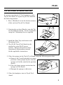
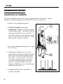
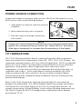
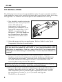
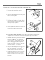
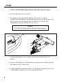
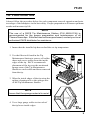
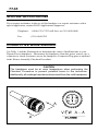
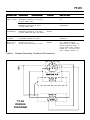
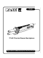
®
TT-65
TT-65 ThermoTweez Handpiece
Operation & Maintenance Instructions
TT-65
TT-65 ThermoTweez Handpiece
Part Number 7025-0001
Manual Number 5050-0336
Rev. C
1
TT-65
These instructions detail the basic operational guidelines for using the TT-65
ThermoTweez handpiece.
INTRODUCTION
The ThermoTweez handpiece provides safe, one-handed removal of a wide variety
of "J" Leaded (PLCC), Leadless (LCCC), SOICs, PQFPs, Bumper Packs (BQFPs),
large extended lead (FlatPacks), SMT Connectors and Chip style components in a
matter of seconds. The ThermoTweez's low temperature, high capacity heating can
remove even the largest components quickly and easily. The ThermoTweez is a
member of the PACE SensaTemp family of advanced SMT/Thru-Hole soldering/
desoldering handpieces and works with any PACE SensaTemp power source.
CAUTION
Always use this handpiece in a well ventilated area. A fume extraction
system such as the PACE Arm-Evac is highly recommended to help
protect personnel from solder flux fumes.
NOTE
Remember that the ThermoTweez is primarily a component removal
tool. Also, a ThermoTweez Cushion Grip Kit (PACE P/N 6993-0155) is
available for applications where the handpiece is under continuous use
at high tip temperature settings. This kit provides added comfort to the
user.
2
TT-65
TIP & TOOL STAND SETUP
If you have purchased a TT-65 handpiece with a
Tip & Tool Stand, set up the Tip & Tool Stand in
the following manner.
1. Place 4 Rubber Feet on the bottom corners
of the enclosed Tip & Tool Stand.
2. Position the enclosed Bracket onto the Tip
& Tool Stand as shown. Secure in position
using the 2 Mounting Screws supplied.
3. Install the Drip Tray and secure with
Mounting Screw.
4. The SX-80 Tip & Tool Stand can be
attached to some PACE power
sources. Refer to the power source
Operation & Maintenance manual
for the applicable instructions.
5. Place the sponge in the Tip & Tool Stand using the following procedure.
a) Remove the 2 small punched out center
portions of the sponge & place into the
sponge well of the stand in the position
shown.
b) Place the large sponge section into the
sponge well as shown.
c) Dampen the sponges with water.
5. Place the handpiece into its Tip & Tool
Stand.
3
TT-65
HANDPIECE SETUP
HANDPIECE ALIGNMENT
Check the handpiece heaters for proper alignment with each other. Proper
handpiece (and tip) alignment is essential for effective operation.
1. Remove any installed tip halves.
2. With the handpiece at room
temperature, adjust the Heaters parallel
to each other (see Á ) using the Tip Gap
Adjustment Thumb Screw (item À ). If
the heater ends are even with each other,
go to "Power Source Connection". If the
ends are not even, go to step 3.
3. Loosen the handpiece Hinge Screw (item
 ) 1/2 turn.
4. Holding the handpiece in a vertical
position (heaters facing down), place the
ends of the two Heaters against a hard
flat surface to insure proper alignment.
The Heater ends should be even with
each other and flush against the flat
surface. Gently push the rear of the
handpiece handles to force both Heaters
against the flat surface.
5. Retighten Hinge Screw (item  ) to
secure in position.
4
TT-65
POWER SOURCE CONNECTION
Connect the handpiece connector plug into one of the Power Receptacles on your
PACE power source in the following manner.
1. Align guide on connector with slot on power
receptacle.
2. Insert connector into power receptacle.
3. Turn the connector housing clockwise to
lock in place.
NOTE
If using your ThermoTweez for the first time or if you have just replaced the
heater, we recommend that you follow the “Heater Burn-in” procedure
(Red tag on handpiece) to increase the life expectancy of the heater.
TIP TEMPERATURE
The TT-65 efficiently transfers heat by contact and typically allows component
removal at relatively low temperatures in the 288 - 343°C (550 - 650°F) range. Tip
temperature and removal times will vary with each application. PACE recommends
the use of a 316°C (600°F) tip temperature setting for initial use in any particular
application. With practice, many components can be removed at lower
temperatures. Use the lowest possible tip temperature that will provide rapid, yet
controlled solder reflow. Lower temperatures extend tip and heater life, allow
solder to remain on the lower surfaces of the tip (to improve thermal linkage
between the tip and the component during component removal) and help prevent
possible board damage.
Refer to the Tip & Temperature Selection System booklet for your particular
handpiece/tip combination. For all Dial Display SensaTemp systems, the booklet
will indicate the correct Dial Setting for the True Tip Temperature desired. On
systems incorporating a Digital Readout, set the desired operating temperature and
Tip Offset Constant for the TT-65 handpiece/tip combination into the channel
powering the TT-65.
5
TT-65
TIP INSTALLATION
The following instructions are for tip installation only. If a tip is currently installed
in the handpiece, remove the installed tip (heater hot) and clean the heater bore using
the supplied 3/16" diameter wire brush prior to the installation of a new tip.
1. Tips should be installed when the
heaters are hot. Turn your power
source ON and set the
temperature for the channel
powering your handpiece to an
appropriate temperature (315°C
(600°F) is recommended for
initial use). Place the handpiece
in a ThermoTweez Hot Cubby
(PACE P/N 6019-0035) when
not in use.
2. Select the proper tip for your application. Refer to Table I or the Tip &
Temperature Selection System booklet.
NOTE Selection of the proper tips is essential for successful repair. If you
do not have the proper tip, call PACE or your local authorized PACE
distributor for assistance. Ask for a copy of the PACE Tip & Applications
Catalog for the latest listing of available tips. Custom tips are available on
request.
3. Each ThermoTweez tip consists of two identical halves. With the
handpiece at the desired temperature, hold the handpiece with the heater
ends pointing up at an angle. Insert the shaft of one tip halve fully into
one of the ThermoTweez handpiece heaters. Insert the shaft of the
second tip halve fully into the other heater.
NOTE If you like, the heater set screws may be tightened very slightly to
hold the tip halves in position while they are being aligned.
4. There are three basic methods for aligning your tips in the ThermoTweez
handpiece depending on tip size and type. Tips should be above solder
melt temperature prior to performing the alignment procedure. Follow
the appropriate procedure (a, b, or c) to install and align the
ThermoTweez tip properly.
6
TT-65
a) Small PLCC Tips (no slots) and Chip Component Tips:
1. Position the tip ends as shown.
2. Squeeze the handpiece closed to press
the tip ends together.
3. Holding the handpiece closed, adjust
the tip ends as necessary so that they
meet precisely together.
4. Gently tighten the heater set screws to
secure the tip halves in position.
b) Large PLCC Tips (with slots): Large PLCC tips (PLCC 44 lead count
or higher) have a small slot cut into the diagonal edge of each halve.
1. With the tip halves oriented as shown,
insert the supplied Tip Alignment
Tool (item À ) between the two tip
halves and position the Alignment
Blocks (item Á ) of the tool into the
tip Slots (item  ) as shown.
2. Squeeze the handpiece closed to grip
the Tip Alignment Tool (item À )
tightly between the two tip halves.
3. Tighten the heater set screw on each
heater using the tip tool or a small
blade screwdriver to secure tip into
position.
7
TT-65
c) SOIC, SOJ/SIMMS Tips & Surface Mount Connector Tips:
1. Position the tip halves as shown.
2. Using the tip gap adjustment thumb screw at the rear of the
ThermoTweez handpiece, increase the space between the tip halves to
allow insertion of the Sponge Tool or Fiber Tool from the Tip
Maintenance Station (PACE P/N 6993-0138).
NOTE
The Tip Tool may also be used for this purpose.
3. Position the Sponge Tool or Fiber Tool between the tip halves as
shown.
4. Squeeze the handpiece closed with the tip ends pressed firmly against
the Sponge Tool or Fiber Tool.
5. Gently tighten the heater set screw on each heater using the tip tool or
a small blade screwdriver to secure tip into position.
8
TT-65
TIP PREPARATION
Always follow the procedure below for each component removal operation and prior
to storage of the handpiece in the hot cubby. Proper preparation will insure optimum
results and increase tip life.
NOTE
The use of a PACE Tip Maintenance Station (P/N 6993-0138) is
recommended for the proper preparation and maintenance of all
ThermoTweez tips. If this item has not been purchased, contact your local
authorized PACE distributor for assistance.
1. Insure that the installed tip has reached the set tip temperature.
2. Use the fiber tool found in the Tip
Maintenance Station to remove all solder
dross and excess solder from the inside
edges of the tip. PACE recommends
placement of the tip over the moistened
sponge area of the Tip Maintenance
Station to catch solder and dross removed
from the tip.
3. Wipe the inside edges of the tip using the
sponge cleaning tool or the sponge area
of the Tip Maintenance Station.
NOTE
Insure that the sponge material is moist.
4. Use a large gauge solder to tin each of
the tip lower inside edges.
9
TT-65
SPECIAL APPLICATIONS
If you require assistance in the use of this handpiece or require assistance with a
special application, contact PACE Applications Support at:
Telephone: 1-888-(535)-7223 (toll-free) or (301) 490-9860
Fax:
(301) 604-8782
CORRECTIVE MAINTENANCE
Use Table 1 and the illustrations to determine the cause of malfunctions to your
ThermoTweez handpiece. Disconnect the handpiece from the power source; use a
voltmeter to check resistance across the handpiece Connector Plug pins as outlined
in the Heater Assembly Checkout Procedure.
CAUTION
The handpiece must be at room temperature when performing the
Checkout Procedure to prevent potential burns to the technician.
Additionally, all readings have been determined from the cold handpiece.
10
TT-65
SY MP TO M
CHECKOUT
No heat on
either heater.
PROCEDURE
CAUSE
S O LU T I O N
Check resistance - Pin 3 to Pin 6.
Resistance should be 110 ohms.
If circuit reads open - -
Open Sensor
Replace Heater
"A".
Check resistance - Pin 2 to Pin 5.
Resistance should be 6 ohms.
If circuit reads open - -
Open Heater
Replace both Heater
Assemblies.
Handpiece
overheating.
Check resistance - Pin 3 to Pin 6.
Resistance should be 110 ohms.
If circuit reads less than 105 ohms -
Shorted
Sensor
Replace Heater Assembly "A".
Heat on only
1 heater.
Check resistance - Pin 2 to Pin 5.
If resistance equals 12 ohms - -
Open Heater
Replace cold Heater
Assembly.
Fuse blows
when unit is
turned on.
Check resistance - Pin 4 to Pin 5
and Pin 4 to Pin 2.
Circuit should read open. If not - -
Shorted
Heater
Remove handpiece side cover
"B". Disconnect wire
connections to Heater "B".
Check resistance again. If
circuit reads open, replace
Heater "B". If circuit is not
open replace Heater "A"
Assembly
Table 1. Heater Assembly Checkout Procedures
TT-65
WIRING
DIAGRAM
11
TT-65
REPLACEMENT PARTS
Table 2 lists the parts needed to maintain your ThermoTweez handpiece.
Description
Part Number
Heater Assembly "A" (with sensor)
6010-0082-P
Heater Assembly "B" (without sensor)
6010-0083-P
Heater Set Screw
1348-0547
Tip Tool
1100-0206
Tip Alignment Tool
1100-0234
Cushion Grip Kit
6993-0155
Replacement Pads For Cushion Grips
1317-0029-P
Tip Redi-Rak
6021-0007-P
3/16 inch O.D. Wire Brush For Cleaning
1127-0014-P
Tip Maintenance Station
6993-0138
Table 2. Replacement Parts
12
TT-65
PACE Incorporated retains the right to make changes to specifications contained
herein at any time, without notice.
Contact your local authorized PACE Distributor or PACE Incorporated to obtain the
latest specifications.
The following are registered trademarks and/or servicemarks of PACE Incorporated,
Laurel Maryland U.S.A. and may only be used to identify genuine PACE products
or services:
Arm-Evac, Cir-Kit, ConducTweez, CRAFT, Flo-D-Sodr, Heat Wave,
HotSpot, LapFlo, MBT, Micro Portable, MicroChine, MiniChine,
Mini-Wave, PACE, Pacenter, Pik-Tip, PETS, Prep-Set,
ResisTweez, SensaTemp, Snap-Vac, Sodr-Pen, Sodr-X-Tractor,
ST, StripTweez, Thermo-Drive, ThermoFlo, ThermoJet,
ThermoPart, ThermoPik, ThermoTweez.
The following are trademarks and/or servicemarks of PACE Incorporated, Laurel
Maryland U.S.A. and may only be used to identify genuine PACE products or
services:
Sodrtek, Toolnet.
Since 1958, PACE Incorporated has provided
advanced technology training in all aspects of hand
soldering, rework and repair.
For any questions regarding this Operation & Maintenance Manual, contact your
local authorized PACE distributor or contact PACE directly at the appropriate
address listed below.
PACE Inc.
9893 Brewers Court, Laurel, Maryland 20723-1990
Tel. (888) 535-7223 (toll-free), (301) 490-9860
FAX 301 483 7030
PACE Europe Ltd. Sherbourne House Sherbourne Drive Tilbrook
Milton Keynes Buckinghamshire England MK7 8HX
Tel. (44) 01908 277 666 FAX (44) 01908 277 777
© 1999 PACE Incorporated, Laurel MD. All rights reserved. Printed in the U.S.A.
13