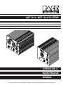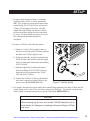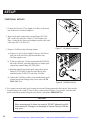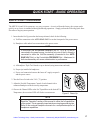
1
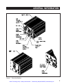
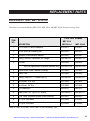
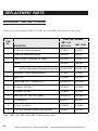
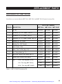
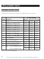
Artisan Technology Group is your source for quality new and certified-used/pre-owned equipment • FAST SHIPPING AND DELIVERY • TENS OF THOUSANDS OF IN-STOCK ITEMS • EQUIPMENT DEMOS • HUNDREDS OF MANUFACTURERS SUPPORTED • LEASING/MONTHLY RENTALS • ITAR CERTIFIED SECURE ASSET SOLUTIONS SERVICE CENTER REPAIRS Experienced engineers and technicians on staff at our full-service, in-house repair center WE BUY USED EQUIPMENT Sell your excess, underutilized, and idle used equipment We also offer credit for buy-backs and trade-ins www.artisantg.com/WeBuyEquipment InstraView REMOTE INSPECTION LOOKING FOR MORE INFORMATION? Visit us on the web at www.artisantg.com for more information on price quotations, drivers, technical specifications, manuals, and documentation SM Remotely inspect equipment before purchasing with our interactive website at www.instraview.com Contact us: (888) 88-SOURCE | [email protected] | www.artisantg.com MBT 201A, MBT 101A SYSTEMS OPERATION & MAINTENANCE MANUAL Artisan Technology Group - Quality Instrumentation ... Guaranteed | (888) 88-SOURCE | www.artisantg.com MANUAL NO. 5050-0381 REV. B SYSTEM QUICK START The MBT 201A and MBT 101A systems are very easy to operate and can be quickly set up for use in standard soldering/desoldering operations. To begin operation of your new system quickly, perform the "Set-Up" and "Quick Start - Basic Operation" procedures detailed on pages 12 - 17 of this manual. When performing other operations which require use of large or specialized tips, PACE recommends that the user read and fully understand the "Operation" portion of this manual in order to utilize the features of this system. i Artisan Technology Group - Quality Instrumentation ... Guaranteed | (888) 88-SOURCE | www.artisantg.com PACE Incorporated retains the right to make changes to specifications contained herein at any time, without notice. Contact your local authorized PACE Distributor or PACE Incorporated to obtain the latest specifications. The following are registered trademarks and/or servicemarks of PACE Incorporated, Laurel Maryland U.S.A. and may only be used to identify genuine PACE products or services: AdapTip, Arm-Evac, Cir-Kit, ComForm I, ConducTweez, CRAFT, Dual Path, Flo-D-Sodr, FuseSet, HandiPik, HotSpot, LapFlo, MBT, Micro Portable, MicroChine, MiniChine, Mini-Wave, PACE, Pacenter, Ped-A-Vac, PETS, Pik-Vac, PRC, PRINT, Pro-Evac, Redi-Rak, ResisTweez, SensaTemp, SMR, Snap-Vac, Sodr-Pen, Sodr-X-Tractor, SR-3, SR-4, ST, StripTweez, SwaPlater, ThermoBand, Thermo-Drive, ThermoJet, ThermoPart, ThermoPik, ThermoTweez, Tip-Evac, VisiFilter. The following are trademarks and/or servicemarks of PACE Incorporated, Laurel Maryland U.S.A. and may only be used to identify genuine PACE products or services: Auto Off, Cubby-Vac, Datastore, Dust Evac, EKO, Lab Evac,PaceLink, PaceNet, Pik & Paste, Prep-Set, Pulse Plate, Spa-Kleen, ThermoBond, TweezPik, Uni-Frame, V-A-N Ventur-Evac. Since 1958, PACE Incorporated has provided advanced technology training in all aspects of hand soldering, rework and repair. Additional copies of this manual or other PACE literature may be obtained from: PACE Incorporated Sales Administration 9893 Brewers Court Laurel MD 20723-1990 (301) 490 - 9860 (301) 498 - 3252 Fax ©1995 PACE Incorporated, Laurel MD. All rights reserved. Printed in the U.S.A. ii Artisan Technology Group - Quality Instrumentation ... Guaranteed | (888) 88-SOURCE | www.artisantg.com TABLE OF CONTENTS TITLE PAGE General Information ............................................................................................................................................... 2 Introduction ................................................................................................................................................. 2 Specifications............................................................................................................................................... 4 Capabilities .................................................................................................................................................. 6 Product Application ..................................................................................................................................... 7 Parts Identification ....................................................................................................................................... 8 Safety .................................................................................................................................................................... 10 Set-up .................................................................................................................................................................... 12 System ....................................................................................................................................................... 12 Handpiece Vacuum/Pressure ..................................................................................................................... 14 Quick Start - Basic Operation .............................................................................................................................. 17 Operation .............................................................................................................................................................. 18 Tip & Temperature Selection ..................................................................................................................... 18 Channel Led Operation .............................................................................................................................. 18 Corrective Maintenance ....................................................................................................................................... 19 VisiFilter Element Replacement ................................................................................................................ 19 Handpieces................................................................................................................................................. 20 Power Source ............................................................................................................................................. 21 Replacement Parts ................................................................................................................................................ 22 Power Source ............................................................................................................................................. 22 Accessory Tray, MBT 201A/J/E ................................................................................................................ 23 Accessory Tray, MBT 101A/J/E ................................................................................................................ 24 Accessory Kit, MBT 201A/J/E.................................................................................................................. 25 Accessory Kit, MBT 101A/J/E.................................................................................................................. 26 Manual Improvement & Comment Form ............................................................................................................ 27 TABLE Table I Table II Table III Table IV Table V Table VI Table VII PAGE Heater Assembly Checkout Procedures.......................................................................................... 20 Power Source Corrective Maintenance .......................................................................................... 21 Power Source Replacement Parts ................................................................................................... 22 MBT 201A/J/E Accessory Tray ..................................................................................................... 23 MBT 101A/J/E Accessory Tray ..................................................................................................... 24 MBT 201A/J/E Accessory Kit ........................................................................................................ 25 MBT 101A/J/E Accessory Kit ........................................................................................................ 26 iii1 Artisan Technology Group - Quality Instrumentation ... Guaranteed | (888) 88-SOURCE | www.artisantg.com GENERAL INFORMATION INTRODUCTION The MBT 201A and MBT 101A Universal Soldering/Desoldering Systems provide the user with the power and versatility to remove and install SMD and Thru-Hole devices. The power source incorporates a highly responsive SensaTemp (closed-loop) temperature control system which provides power to the two output channels on the MBT 201A systems and to a single output channel on the MBT 101A systems. Accessory handpieces (standard & optional) and special use tips allow the user to remove and replace a wide variety of surface mount components. The self-contained AUTO SNAP-VAC pump provides an automatic minimum on-time of 1.2 seconds to virtually eliminate re-sweat joints, tip clogging and maintenance while dramatically increasing tip life. Virtually all of todays specialized handpieces with large SMD tips suffer from a problem in which the actual tip temperature that the work sees can be more than 100°F cooler than the Set Tip Temperature on the Variable Temperature Control. MBT 201A/101A systems feature PACEs unique Tip & Temperature Selection System which allows the user to set the true temperature desired for any size and type of tip or handpiece. The MBT 101A and MBT 201A systems are available in either the 115 VAC version, 100 VAC version or 230 VAC version. The 230 VAC version system bears the CE Conformity Marking which assures the user that it conforms to all the requirements of council directive EMC 89/336/EEC. The systems package the power source with a selection of accessories and functional aids. These systems are as follows. 2 Artisan Technology Group - Quality Instrumentation ... Guaranteed | (888) 88-SOURCE | www.artisantg.com GENERAL INFORMATION MBT 101A SYSTEM - Consists of PPS 75A (115 VAC, 60 Hz Version) Power Source, SX-70 Sodr-X-Tractor, SX Tip & Tool Stand, Tip & Temperature Selection System Charts and Accessory Kit. MBT 101AJ SYSTEM - Consists of PPS 75AJ (100 VAC, 50/60 Hz Version) Power Source, SX-70 Sodr-XTractor, SX Tip & Tool Stand, Tip & Temperature Selection System Charts and Accessory Kit. MBT 101AE SYSTEM - Consists of PPS 75AE (230 VAC, 50 Hz Version) Power Source, SX-70 Sodr-XTractor, SX Tip & Tool Stand, Tip & Temperature Selection System Charts and Accessory Kit. MBT 201A SYSTEM - Consists of PPS 80A (115 VAC, 60 Hz Version) Power Source, SP-2A Sodr-Pen Soldering Iron, SX-70 Sodr-X-Tractor, SX & SP Tip & Tool Stands, Tip & Temperature Selection System Charts and Accessory Kit. MBT 201AJ SYSTEM - Consists of PPS 80AJ (100 VAC, 50/60 Hz Version) Power Source, SP-2A Sodr-Pen Soldering Iron, SX-70 Sodr-X-Tractor, SX & SP Tip & Tool Stands, Tip & Temperature Selection System Charts and Accessory Kit. MBT 201AE SYSTEM - Consists of PPS 80AE (230 VAC, 50 Hz Version) Power Source, SP-2A Sodr-Pen Soldering Iron, SX-70 Sodr-X-Tractor, SX & SP Tip & Tool Stands, Tip & Temperature Selection System Charts and Accessory Kit. PETS 5A, 5AE SYSTEMS - PACE Educational Systems containing everything required for step-by-step training in high reliability soldering & desoldering. Consists of MBT 201A or MBT 201AE systems plus instructional Videos, Manuals & Skills Kits. The SR-3 Safety Rated designation on the front panel is your assurance that the MBT 101A/J/E and MBT 201A/J/E systems: Meet all applicable EOS/ESD, temperature stability and other government and industry specification requirements (including MIL-STD-2000A); contain PACEs unique SensaTemp temperature management system for high performance and safety, plus a Tip Offset Compensation feature for superior thermal process control. Artisan Technology Group - Quality Instrumentation ... Guaranteed | (888) 88-SOURCE | www.artisantg.com 3 GENERAL INFORMATION SPECIFICATIONS POWER REQUIREMENTS PPS 75A (MBT 101A System) - Version operates on 97-127 VAC, 50/60 Hz. 86 Watts, 0.75 Amp typical; 120 Watts, 1.0 Amp maximum PPS 75AJ (MBT 101AJ System) - Version operates on 90-115 VAC, 50/60 Hz. 86 Watts, 0.86 Amp typical; 120 Watts, 1.2 Amp maximum PPS 75AE (MBT 101AE System)- Version operates on 196-264 VAC, 50 Hz. 86 Watts, 0.44 Amp typical; 100 Watts, 0.55 Amp maximum PPS 80A (MBT 201A System) - Version operates on 97-127 VAC, 50/60 Hz. 138 Watts, 1.2 Amp typical; 184 Watts, 1.6 Amp maximum PPS 80AJ (MBT 201AJ System) - Version operates on 90-115 VAC, 50/60 Hz. 138 Watts, 1.4 Amp typical; 184 Watts, 1.8 Amp maximum PPS 80AE (MBT 201AE System)- Version operates on 196-264 VAC, 50 Hz. 138 Watts, 0.6 Amp typical; 199 Watts, 0.9 Amp maximum VACUUM AND AIR Measurements at front panel AUTO SNAP-VAC and Controllable PRESSURE Ports of power source. Vacuum Rise Time: Evacuates 33 cc (2 cubic inch) volume to 25 cm Hg. (10 in. Hg.) in 200 ms. Vacuum: 51 cm Hg. (20 in. Hg.) (nominal). Pressure: .48 Bar (7 P.S.I.) (nominal, "MAX" setting). Air Flow: 9 SLPM (0.32 SCFM) maximum. ENVIRONMENTAL REQUIREMENTS Ambient Operating Temperature: 0°C to 50°C (32°F to 120°F). Storage Temperature: 4 -40°C to 100°C (-40°F to 212°F). Artisan Technology Group - Quality Instrumentation ... Guaranteed | (888) 88-SOURCE | www.artisantg.com GENERAL INFORMATION PHYSICAL PARAMETERS Size (all systems): 13.5 cm H X 16.5 cm W X 20.3 cm D (5.3 in. H X 6.5 in. W X 8.0 in. D) Weight (all systems): PPS 75A/J/E - 3.7 kg. (8.1 lbs.) PPS 80A/J/E - 3.7 kg. (8.1 lbs.) TEMPERATURE SPECIFICATIONS Tip Temperature Range: 232°C to 482°C (450°F to 900°F), nominal. Accuracy: ±5% of control setting Tip Temperature Stability: ±1.1°C (2°F) at idle from Set Tip Temperature. NOTE True minimum and maximum Operating Tip Temperatures may vary depending on handpiece & tip selection. EOS/ESD Tip-To-Ground Resistance: Less than 2 ohms. AC Leakage: Less then 2 millivolts RMS from 50Hz to 500Hz, min. Artisan Technology Group - Quality Instrumentation ... Guaranteed | (888) 88-SOURCE | www.artisantg.com 5 GENERAL INFORMATION CAPABILITIES All capabilities are dependent upon the use of the appropriate Functional Accessories or Work Aids. Available SensaTemp handpieces and their associated assembly and repair functions are listed below (a manual is provided separately with each handpiece which describes the applications and recommended procedures for that particular tool). SP-2A Sodr-Pen Soldering Iron - Standard handpiece on MBT 201A, MBT 201AJ & MBT 201AE systems. Provides a wide range of SMD and thru-hole installation and removal capability as well as unsurpassed thermal performance on heavy, multilayer thru-hole assemblies at safe, lower working temperatures. A wide variety of 3/16" shank, quick change thru-hole and SMD tips (for chip components, SOTs, SOICs and other components) are available. SP-1A Sodr-Pen Soldering Iron - Uses 1/8" shank tips and features a slimmer, more compact heater than the SP-2A Sodr-Pen for easier access on densely populated assemblies. SX-70 Sodr-X-Tractor Handpiece - Standard handpiece on MBT 201A, MBT 201AJ, MBT 201AE, MBT 101A, MBT 101AJ & MBT 101AE systems. Provides thermally enhanced thru-hole desoldering on heavy multilayer assemblies, especially during continuous use. With the unique Flo-D-Sodr tip, the Sodr-X-Tractor performs safe, continuous SMT land cleaning and preparation. The slim-line, pencil-grip design and fingeractuated vacuum switch allow easy use and manipulation in tight places. TT-65 ThermoTweez Handpiece - Provides safe, one-handed reflow and removal of PLCCs, LCCCs, chip components and other surface mount devices. Its high thermal capacity and targeted heat quickly removes large SMDs without damage to the board or adjacent components, even on heavy, multilayer assemblies. The unique, vertically oriented design and a wide variety of quick change tips easily reach into tight work areas for safe SMD removal. TP-65 ThermoPik Handpiece - Provides safe, one-handed reflow and removal of a wide variety of PQFPs and FlatPacks in just seconds. The high thermal efficiency design targets controlled SensaTemp heat directly at the solder joints, away from sensitive substrate areas and adjacent components. The ThermoPiks self-adjusting integral vacuum pick and unique design provide easy, one-handed operation. TJ-70 Mini ThermoJet Handpiece - Provides safe, rapid installation of SMDs including chip components, SOTs, SOICs, PLCCs, LCCCs and FlatPacks. The slim-line design and precision focused air flow lets you easily target controlled heat right at the solder joints without damaging the board or adjacent components. A finger-actuated air switch and SensaTemp control provide safe, on-demand capability without constant running of the air pump. 6 Artisan Technology Group - Quality Instrumentation ... Guaranteed | (888) 88-SOURCE | www.artisantg.com GENERAL INFORMATION NOTE The MBT 101A/J/E and MBT 201A/J/E products feature PACE’s unique SensaTemp closed loop temperature management system which will function only with the SenaTemp handpieces listed above. Do not attempt to use any other handpiece. Likewise, use SensaTemp handpieces on only those systems with an SR-3 or SR-4 rating (marked on front panel of power source). These include other MBT systems (MBT 101A, MBT 201A and higher) and all ST series systems. PRODUCT APPLICATION These products are very versatile and may be used to satisfy a variety of application requirements. If you require assistance in the use of this product for your particular application, contact your local authorized PACE distributor or call PACE Applications Engineering at Tel. # (301) 490-9860, Fax # (301) 604-9215. Artisan Technology Group - Quality Instrumentation ... Guaranteed | (888) 88-SOURCE | www.artisantg.com 7 GENERAL INFORMATION PARTS IDENTIFICATION 1. POWER SWITCH - Turns system ON (1) and OFF (0); controls input power to system. 2. CH 1 VARIABLE TEMPERATURE CONTROL - Allows the operator to adjust the tip temperature for handpiece/tip combination connected to channel 1. 3. CH 2 VARIABLE TEMPERATURE CONTROL (MBT 201A/J/E Systems Only) - Allows the operator to adjust the tip temperature for handpiece/tip combination connected to channel 2. 4. CH 1 POWER RECEPTACLE - Provides power, tip ground, sensing circuitry and finger switch connection from MBT system to the handpiece connected to channel 1. 5. CH 2 POWER RECEPTACLE (MBT 201A/J/E Systems Only) - Provides power, tip ground, sensing circuitry and finger switch connection from MBT system to the handpiece connected to channel 2. 6. CH 1 LED - Green LED provides visual indication of duty cycle control of channel 1. Indicator lights as power is applied to the connected handpiece. 7. CH 2 LED (MBT 201/J/E Systems Only) - Green LED provides visual indication of duty cycle control of channel 2. Indicator lights as power is applied to the connected handpiece. 8. AUTO SNAP-VAC PORT - Quick connect fitting which provides quick-rise vacuum for Sodr-XTractor or ThermoPik handpieces. Vacuum is present when handpiece finger switch or optional foot pedal is actuated. Vacuum continues a minimum of 1.2 seconds after switch (or foot pedal) actuation. 9. CONTROLLABLE PRESSURE PORT - Quick connect fitting with adjustable valve which provides variable air flow for the Mini ThermoJet handpiece. Air pressure is present when handpiece finger switch or optional foot pedal is actuated. Air pressure ceases 1.2 seconds after switch (or foot pedal) is released. 10. EARTH GROUND RECEPTACLE - Provides positive earth ground to which a ground cable can be connected from the workpiece or work surface as part of a static control program. 11. POWER CORD - Provides main power to system from AC outlet to AC Power Receptacle. 12. AC POWER RECEPTACLE/FUSE HOLDER - Receptacle for providing power to the system from AC outlet through Power Cord, and location of fuse which protects system from overcurrent conditions. 13. FUSE - Provides overload protection for MBT system. 14. FOOT PEDAL RECEPTACLE - Input for foot pedal (optional) which actuates vacuum or pressure to the air-operated handpieces. 8 Artisan Technology Group - Quality Instrumentation ... Guaranteed | (888) 88-SOURCE | www.artisantg.com GENERAL INFORMATION Figure 1. Parts Identification Artisan Technology Group - Quality Instrumentation ... Guaranteed | (888) 88-SOURCE | www.artisantg.com 9 SAFETY The purpose of this "SAFETY" section is to inform users of the heading guidelines used in this manual to indicate special Notes, Cautions, Warnings or Dangers. Also included are recommended precautions which must be observed when operating or servicing this product. HEADING GUIDELINES PACE adheres to the following Heading Guidelines (based on OSHA guidelines) when listing special information or precautions to be taken. Especially important are all procedures and practices which, if not strictly observed, could result in injury or loss of life. These "NOTES", "CAUTIONS","WARNINGS" and "DANGERS" are inserted in this manual whenever deemed necessary. They appear in a blocked off form with double outline and a shaded background to highlight the information as shown below. NOTE XXXXXXXXXXXXXXXXXXXXXXXXXXXXXXXXXXXXXXXXXXXXXXXXXX NOTE Used to indicate a statement of company recommendation or policy. The message may relate directly or indirectly to the safety of personnel or protection of property. NOTE is not associated directly with a hazard or hazardous situation and is not used in place of "CAUTION", "WARNING" or "DANGER". CAUTION Used to indicate a hazardous situation which may result in minor or moderate injury. May also be used to alert personnel to conditions, procedures and practices which, if not observed, could result in damage to or destruction of the product or other equipment. WARNING Used to define additional information that if not closely followed might result in serious damage to equipment and represent a potential for serious personnel injury. DANGER Defines additional information that if not closely followed might result in severe personnel injury or death. Danger is not used for property damage unless personal injury risk is present. 10 Artisan Technology Group - Quality Instrumentation ... Guaranteed | (888) 88-SOURCE | www.artisantg.com SAFETY PRECAUTIONS The following are general safety precautions which personnel must understand and follow when using or servicing this product. These precautions may or may not be included elsewhere in this manual. USEAGE PRECAUTIONS CAUTIONS 1. SensaTemp handpiece heaters and installed tips are hot when handpiece is powered on. DO NOT touch either the heater or tip. Severe burns may result! Always store handpiece in the appropriate cubby when not in use. 2. Always use this system in a well ventilated area. A fume extraction system such as those marketed by PACE are highly recommended to protect personnel from solder flux fumes. 3. Exercise proper precautions when using chemicals (e.g., solder paste). Refer to the Material Safety Data Sheet (MSDS) supplied with each chemical and adhere to all safety precautions recommended by the manufacturer. NOTES 1. The solder collection chamber in the PACE Sodr-X-Tractor is made of glass. Never remove this chamber using pliers. Breakage of the chamber may result. Always remove using the procedures recommended by PACE in the associated handpiece manual. 2. The front end (heater end) of the glass solder collection chamber in the PACE Sodr-X-Tractor is hot when the handpiece is in use. When removing the chamber for cleaning, grip the chamber at the rear seal. Never touch the front end of the glass chamber with bare hands. Allow the chamber to cool before cleaning. 3. Always store any connected handpiece in the appropriate Tip & Tool Stand. SERVICING PRECAUTIONS DANGERS POTENTIAL SHOCK HAZARD - Repair procedures performed on this product should be performed by qualified service personnel only. Line voltage parts will be exposed when equipment is disassembled. Service personnel must avoid contact with these parts when troubleshooting the power source. NOTES Refer to the MBT 201, MBT 101, ST 50 Service Manual (P/N 5050-0340) whenever service is required. To insure continued peak performance, use genuine PACE replacement parts. Artisan Technology Group - Quality Instrumentation ... Guaranteed | (888) 88-SOURCE | www.artisantg.com 11 SET-UP SYSTEM Using Figures 1 thru 4 as a guide, set up the MBT 201A or MBT 101A system using the following steps. 1. Store the shipping container(s) in a convenient location. Reuse of these containers will prevent damage if you store or ship the system. 2. Place Power Switch in the “Off” or “0” position. 3. Position the system on a convenient bench. 4. Plug the Power Cord into AC Power Receptacle/Fuse Holder at the rear panel of the system. IMPORTANT The AC supply receptacle must be checked to insure proper grounding before initial system operation. 5. Assemble the Tip & Tool Stand(s) and, if desired, attach to the power source. Assembly instructions are enclosed with each stand. 6. If you have purchased the optional Tip & Temperature Selection System Chart Holder, attach to the top of the power source using the supplied instructions. 7. Install the Tip & Temperature Selection System Charts booklet onto Chart Holder (if present). This booklet is supplied with each system. 12 Figure 2. Tip & Temperature Chart Holder (Optional) Artisan Technology Group - Quality Instrumentation ... Guaranteed | (888) 88-SOURCE | www.artisantg.com SET-UP 8. Place handpiece(s) into the Tip & Tool Stand(s). 9. Using Figure 3 as a guide, connect handpiece connector(s) to the power source Power Receptacle(s) in the following manner: a) With the Connector Key end facing the power source, turn the Locking Ring fully counterclockwise. b) Align the Connector Key with the Receptacle Keyway. c) Insert the connector into the Power Receptacle. d) Turn the Locking Ring fully clockwise to lock in place. Figure 3. Handpiece Connection 10. To avoid confusion among handpieces on MBT 201A systems, PACE recommends the use of colored markers (P/N 6993-0136 Cable Marker Kit) to identify the particular handpiece power cable and/or air hose. Attach any two like colored markers, one to each end of the handpiece power cable or air hose. Select and use a different color marker for each handpiece. 11. If you have purchased the optional foot pedal, insert the foot pedal connector plug into the Foot Pedal Receptacle on the rear panel of the power source. 12. Plug the prong end of the Power Cord into a convenient three wire grounded outlet. 13. Place the POWER Switch in the “On” or “1” position. The system is now ready for operation. Figure 4. Foot Pedal Connection Artisan Technology Group - Quality Instrumentation ... Guaranteed | (888) 88-SOURCE | www.artisantg.com 13 SET-UP HANDPIECE VACUUM/PRESSURE AIR HOSE CONNECTION There are two methods of attaching the Air Hose from the PACE power source to an air handpiece. Select the method which best suits your needs. The Quick Connect Method is best suited for configurations where multiple air handpieces may be in use. The Traditional Method is best suited for single air handpiece configurations. CAUTION Regardless of connection method, ensure that only one Air Hose is connected to theVisiFilter assembly ( connected to the AUTO SNAP-VAC Port) or Controllable PRESSURE Port at one time. Attachment to both ports simultaneously will cause a deterioration of performance. QUICK CONNECT METHOD To set up each air handpiece for the quick connect operation, perform the following steps. 1. Attach a 1 inch length (2.5cm) of clear pvc Air Hose (P/N 1325-0003-07) to the metal tube in the back of each handpiece. 2. To the other end of the 1 inch (2.5cm) clear pvc Air Hose attach a female quick connect hose mount Fitting (P/N 1259-0086). Secure this short Air Hose to the handpiece power cable with one cable clip (P/N 1321-0085-01). 14 Figure 5. Handpiece Quick Connect Hose Artisan Technology Group - Quality Instrumentation ... Guaranteed | (888) 88-SOURCE | www.artisantg.com SET-UP 3. Prepare a quick connect Air Hose by inserting a metal hose clamp (P/N 1211-0036, standard on MBT 201A systems) & a male quick connect hose mount Fitting (P/N 1259-0087) into each end of a 54 inch (137cm) length of Air Hose. Push the ridged ends of the Fittings into the hose; slide & twist the metal hose clamps over the connections to secure. You may already have this piece if you have other quick disconnect handpieces configured. 4. Prepare a VisiFilter in the following manner. a) Connect a 1 inch (2.5cm) length of clear pvc Air Hose to each side of the VisiFilter; push and turn hose onto VisiFilter nipple to seat. b) To the free end of the Air Hose connected to the FLOW IN side of the VisiFilter, insert the ridged end of a female quick connect hose mount Fitting (P/N 1259-0086). c) Insert the ridged end of a male quick connect hose mount Fitting (P/N 1259-0087) in the free end of the Air Hose connected to the FLOW OUT side of the VisiFilter. d) Connect the VisiFilter Air Hose (with attached male quick connect hose mount Fitting) to the power source AUTO SNAP-VAC Port. Figure 6. VisiFilter Set-Up 5. For vacuum, insert the male quick connect hose mount Fitting connected to the long Air Hose into the female Fitting on the 1 inch (2.5cm) Air Hose (connected to VisiFilter). For pressure, insert the male quick connect hose mount Fitting directly into the Controllable PRESSURE Port. CAUTION When removing any Air Hose, turn and pull. DO NOT attempt to pull Air Hose directly off. Damage to or breakage of Vacuum Fitting or VisiFilter may occur. Artisan Technology Group - Quality Instrumentation ... Guaranteed | (888) 88-SOURCE | www.artisantg.com 15 SET-UP TRADITIONAL METHOD 1. Connect the 54 inch (137cm) length of Air Hose to the metal tube in the back of each air handpiece. 2. Insert a male quick connect hose mount Fitting (P/N 12590087) to the free end of the 54 inch (137cm) length of Air Hose. Secure the Air Hose to the handpiece power cable with cable clips (P/N 1321-0085-01). 3. Prepare a VisiFilter in the following manner. Figure 7. Air Hose Connection a) Connect a 1 inch (2.5cm) length of clear pvc Air Hose to each side of the VisiFilter; push and turn hose onto VisiFilter nipple to seat. b) To the free end of the Air Hose connected to the FLOW IN side of the VisiFilter, insert the ridged end of a female quick connect hose mount Fitting (P/N 1259-0086). c) Insert the ridged end of a male quick connect hose mount Fitting (P/N 1259-0087) in the free end of the Air Hose connected to the FLOW OUT side of the VisiFilter. d) Connect the VisiFilter Air Hose (with attached male quick connect hose mount Fitting) to the power source AUTO SNAP-VAC Port. Figure 8. VisiFilter Set-Up 4. For vacuum, insert the male quick connect hose mount Fitting connected to the long Air Hose into the female Fitting on the 1 inch (2.5cm) Air Hose (connected to VisiFilter). For pressure, insert the male quick connect hose mount Fitting directly into the Controllable PRESSURE Port. CAUTION When removing any Air Hose, turn and pull. DO NOT attempt to pull Air Hose directly off. Damage to or breakage of Vacuum Fitting or VisiFilter may occur. 16 Artisan Technology Group - Quality Instrumentation ... Guaranteed | (888) 88-SOURCE | www.artisantg.com QUICK START - BASIC OPERATION QUICK START PROCEDURE The MBT 201A and 101A systems are very easy to operate. As received from the factory, the system can be quickly set up for use in standard soldering/desoldering operations. Simply perform the following Quick Start Procedure to begin system operation. 1. Insure that the Set-Up procedure has been performed; check for the following: a) VisiFilter connection to the AUTO SNAP-VAC Port on the front panel of the power source. b) Handpiece cable and air hose connections to the power source. NOTE If more than one air-operated handpiece (SX-70, TJ-70 or TP-65) is connected to the power source, insure that only one of the Air Hoses is connected to either the VisiFilter assembly (connected to the AUTO SNAP-VAC Port) or the Controllable PRESSURE Port. Attachment to both simultaneously will cause a deterioration in performance. a) All handpiece Tip & Tool Stands set up as desired (using instructions enclosed). b) Proper tips installed in handpieces. c) Power cord connection between the house AC supply receptacle and the power source. 2. Turn the Power Switch to the "On" ("l") position. 3. Adjust the Variable Temperature Control of each channel with a connected handpiece to the desired tip temperature. 4. Observe the Channel LEDs as the Set Tip stabilizes at the desired Tip Temperature, the associated LED will flash at a constant rate. Figure 9. Power Up NOTE Read the "Operation" section of this manual to utilize the full capabilities of the system. This is especially important when using large soldering tips. Refer to the enclosed handpiece manuals for a complete description of handpiece capabilities. Artisan Technology Group - Quality Instrumentation ... Guaranteed | (888) 88-SOURCE | www.artisantg.com 17 OPERATION TIP & TEMPERATURE SELECTION TIP OFFSET Differences between temperature settings and true tip temperatures are negligible when using Thru-hole, single point soldering or desoldering tips. With any heating system however, actual tip temperatures can differ greatly from temperature control settings when using larger SMT soldering tips. This difference is called Tip Temperature Offset. The PACE “Tip & Temperature Selection System” allows you to select and maintain a True Tip Temperature for any size and type of tip using the appropriate Tip Offset compensation value. The PACE Tip & Temperature Selection System allows you to select and maintain a True Tip Temperature for any size and type of SMT tip. PACE recommends the use of the Tip & Temperature Selection System Booklet (PACE P/N 5050-0251 included with your system) as a guide to accurately set and maintain a true tip temperature. Select the appropriate handpiece chart (in the booklet) for your application; identify the correct tip and Dial/Display setting for the desired tip temperature. Then set the Variable Temperature Control (Dial/Display setting) for the channel powering the handpiece to obtain the desired True Tip Temperature. VARIABLE TEMPERATURE CONTROL Adjust the Variable Temperature Control(s) to the desired temperature setting. Notice that the control dial has a Gray scale denoting temperature in °C (Celsius) and a Yellow scale denoting temperature in °F (Fahrenheit). These numerical scales denote the set tip temperature times 100 (e.g., "3" on the Yellow scale is 3 x 100 or 300°C). CHANNEL LED OPERATION Figure 10. Adjust Temperature The Channel LED(s) are a visual indication of Power Output status. Following is an explanation of these status indicators. LED Full On - Continuous power is being delivered to the handpiece connected to the associated channel. This condition is evident when the system is first powered up (handpiece heater cold) or the Variable Temperature Control is increased. LED Flashing - Indicates that the set tip temperature (as set on the associated Variable Temperature Control) has been reached. Power to the handpiece is cycling Off and On to maintain set temperature. LED Off - No power is being delivered to the handpiece connected to the associated channel. This condition is evident if the Variable Temperature Control is decreased. 18 Artisan Technology Group - Quality Instrumentation ... Guaranteed | (888) 88-SOURCE | www.artisantg.com CORRECTIVE MAINTENANCE VISIFILTER ELEMENT REPLACEMENT Follow the procedure listed below to replace the VisiFilter element when it becomes clogged or discolored. 1. Disconnect the handpiece air hose by gently turning and pulling the coupled Fittings. 2. Disconnect the Visifilter and hose assembly from the Power Source by gently turning and pulling the male Fitting inserted into the AUTO SNAP-VAC Port. 3. Disconnect VisiFilter from both attached 1 inch air hoses by gently turning and pulling the VisiFilter while holding each of the hoses. 4. Separate the 2 plastic housing halves of the VisiFilter in the following manner. a) Grasp the VisiFilter in the palm of the hand with the Male Nib (air hose connection) marked "FLOW IN" facing you. b) Pull against one of the Wing Tabs while pulling on the Male Nib with the free hand to open the interconnection of the plastic housings at that Wing Tab. c) Pull against the second Wing Tab while pulling on the Male Nib to open the remaining interconnection and separate the plastic housings. 5. Remove the old or discolored Element and discard. 6. Insert the replacement VisiFilter Element into the housing marked "FLOW IN". Center the Element in the housing well. 7. Squeeze the 2 plastic housing halves together using 4 plastic Bumps on the housing marked "FLOW OUT" as pressure points. The 2 plastic housings will snap together and lock the VisiFilter Element in position. 8. Reconnect the 1 inch air hoses (removed in step 3) to the VisiFilter. Figure 11. VisiFilter Element Replacement 9. Attach VisiFilter and hose assembly to Power Source by inserting male Fitting into the AUTO SNAP-VAC Port. Artisan Technology Group - Quality Instrumentation ... Guaranteed | (888) 88-SOURCE | www.artisantg.com 19 CORRECTIVE MAINTENANCE HANDPIECES The following "Heater Assembly Checkout Procedures" are applicable to all PACE SensaTemp handpieces except for the TT-65 ThermoTweez handpiece. Refer to either of the TT-65 manuals (P/N 5050-0300 or 5050-0336) for troubleshooting procedures pertinent to that handpiece. Perform the "Heater Assembly Checkout Procedures" with the handpiece (and heater) at room temperature. If the handpiece is warm, resistance readings will be different from those shown. SYMPTOM No heat. CHECKOUT PROCEDURE Open Heater. Replace Heater Assembly. Check resistance - Pin 3 to Pin 6. If circuit reads open - Open Sensor. Replace Heater Assembly. Check resistance - Pin 2 to Pin 5. Refer to "Heater Specifications" column. If resistance is low - Check resistance - Pin 4 to a NEW Tip. Resistance should be less than 2 ohms. If not - HEATER SPECIFICATIONS SX-70 = 8 - 10 ohms SP-1A = 10 - 12 ohms SP-2A = 8 - 10 ohms TP-65 = 9 - 11 ohms Shorted Sensor. Replace Heater Assembly. Solder short in Handpiece. Remove Short. Replace Heater Assembly & Fuse F1. Shorted Heater. No Ground on Tip. SOLUTION Check resistance - Pin 2 to Pin 5. Refer to "Heater Specifications" column. If resistance is high - Handpiece is Check resistance - Pin 3 to Pin overheating. 6. Resistance should be 110 ohms. If circuit resistance reads less than 105 ohms Fuse blows when unit is turned on. CAUSE Oxidation buildup in Heater Bore. Defective Heater. TJ-70 = 6 ohms Replace Heater Assembly & Fuse F1. Clean Heater Bore using appropriate wire brush. Replace Heater Assembly. Table I. Heater Assembly Checkout Procedures 20 Artisan Technology Group - Quality Instrumentation ... Guaranteed | (888) 88-SOURCE | www.artisantg.com CORRECTIVE MAINTENANCE Figure 12. Connector Plug Wiring POWER SOURCE Most malfunctions are simple and easy to correct. Refer to the table shown below to clear these malfunctions. SYMPTOM PROBABLE CAUSE SOLUTION No power to system. Blown Fuse (F1). Replace fuse F1 located on rear of Power Source in the AC Receptacle/Fuse Holder. No heat on handpiece. Other handpieces work on Power Source channel. Defective Heater. See Table l or refer to handpiece Manual. No heat on handpiece. Other handpieces do not work on Power Source channel. Defective control circuit. Contact PACE Customer Service. Table II. Power Source Corrective Maintenance Artisan Technology Group - Quality Instrumentation ... Guaranteed | (888) 88-SOURCE | www.artisantg.com 21 REPLACEMENT PARTS POWER SOURCE Listed below are the replacement parts which may be ordered directly from PACE sales or through your local authorized PACE distributor. Refer to Figure 1, Page 9. To obtain any parts other than those listed below, contact PACE Customer Service directly at Tel. # (301) 490-9860 or Fax # (301) 604-9215. PACE PART NUMBER ITEM NO. DESCRIPTION MBT 201A MBT 101A MBT 201AJ MBT 101AJ MBT 201AE MBT 101AE 1 Power Switch 1157-0052 1157-0052 1157-0052 2 AC Power Receptacle/Fuse Holder 1207-0151 1207-0151 1207-0151 3 Fuse (F1), 1.25A (MBT 201A, MBT 101A) 1159-0217 N/A N/A 1.25A (MBT 101AJ) N/A 1159-0251 N/A 1.6A (MBT 201AJ) N/A 1159-0256 N/A 0.63A (MBT 201AE, MBT 101AE) N/A N/A 1159-0214 5050-0340 5050-0340 5050-0340 4 Service Manual Table III. Power Source Replacement Parts 22 Artisan Technology Group - Quality Instrumentation ... Guaranteed | (888) 88-SOURCE | www.artisantg.com REPLACEMENT PARTS ACCESSORY TRAY, MBT 201A/J/E Listed below are items included in MBT 201A, MBT 201AJ and MBT 201AE System Accessory Trays. PACE PART NUMBER ITEM NO. DESCRIPTION MBT 201A MBT 201AJ MBT 201AE 1 SX-70 Sodr-X-Tractor Handpiece 6010-0077 6010-0077 2 SP-2A Sodr-Pen Soldering Iron 6025-0014 6025-0014 3 Operation & Maintenance Manual 5050-0381 5050-0381 4 Tubing, Silicone, Translucent, 54" Length 1342-0001-13 1342-0001-13 5 VisiFilter 1309-0028 1309-0028 VisiFilter Replacement Elements (optional item) 1309-0027-P50 1309-0027-P50 6 Bristle Brush, Glass Chamber Cleaning 1127-0002 1127-0002 7 Power Cord 1332-0094 1332-0093 8 Tubing, Clear PVC, 1" Length (Qty. 2) 1325-0003-07 1325-0003-07 9 Wire Brush, 3/16" Dia. 1127-0014 1127-0014 10 Wire Brush, 1/8" Dia. 1127-0006 1127-0006 11 Tip Cleaning Kit 6993-0151 6993-0151 12 AdapTip Kit (1/8" Tip to 3/16" Shank) 1360-0083-P1 1360-0083-P1 13 Tip & Temp. Selection System Charts (booklet) 5050-0251 5050-0251 14 SP Tip & Tool Stand 6019-0043 6019-0043 15 SX Tip & Tool Stand 6019-0044 6019-0044 Table IV. MBT 201A, MBT 201AJ, MBT 201AE Accessory Tray Artisan Technology Group - Quality Instrumentation ... Guaranteed | (888) 88-SOURCE | www.artisantg.com 23 REPLACEMENT PARTS ACCESSORY TRAY, MBT 101A/J/E Listed below are items included in MBT 101A, MBT 101AJ and MBT 101AE System Accessory Trays. PACE PART NUMBER ITEM NO. DESCRIPTION MBT 101A MBT 101AJ MBT 101AE 1 SX-70 Sodr-X-Tractor Handpiece 6010-0077 6010-0077 2 Operation & Maintenance Manual 5050-0381 5050-0381 3 Tubing, Silicone, Translucent, 54" Length 1342-0001-13 1342-0001-13 4 VisiFilter 1309-0028 1309-0028 VisiFilter Replacement Elements (optional item) 1309-0027-P50 1309-0027-P50 5 Bristle Brush, Glass Chamber Cleaning 1127-0002 1127-0002 6 Power Cord 1332-0094 1332-0093 7 Tubing, Clear PVC, 1" Length (Qty. 2) 1325-0003-07 1325-0003-07 8 Wire Brush, 3/16" Dia. 1127-0014 1127-0014 9 Wire Brush, 1/8" Dia. 1127-0006 1127-0006 10 AdapTip Kit (1/8" Tip to 3/16" Shank) 1360-0083-P1 1360-0083-P1 11 Tip Cleaning Kit 6993-0151 6993-0151 12 SX Tip & Tool Stand 6019-0044 6019-0044 13 Tip & Temp. Selection System Charts (booklet) 5050-0251 5050-0251 Table V. MBT 101A, MBT 101AJ, MBT 101AE Accessory Tray 24 Artisan Technology Group - Quality Instrumentation ... Guaranteed | (888) 88-SOURCE | www.artisantg.com REPLACEMENT PARTS ACCESSORY KIT, MBT 201/J/E Listed below are items included in MBT 201A, MBT 201AJ and MBT 201AE System Accessory Kits. PACE PART NUMBER ITEM NO. DESCRIPTION MBT 201A MBT 201AJ MBT 201AE 1 Tip Tool 1100-0206 1100-0206 1100-0206 2 Desoldering Tip, 3/16" Shank, .040 I.D. 1121-0342 1121-0342 1121-0342 3 Desoldering Tip, 1/8" Shank, .040 I.D. 1121-0254 1121-0254 1121-0254 4 Desoldering Tip, 1/8" Shank, Angled, .040 I.D. 1121-0262 1121-0262 1121-0262 5 Soldering Tip, 1/8" Chisel 1121-0337 1121-0337 1121-0337 6 Soldering Tip, 1/32" Conical 1121-0336 1121-0336 1121-0336 7 Sodr-X-Tractor Filter 1309-0018 1309-0018 1309-0018 8 Holder, Tube To Wire (pkg. of 6) 1321-0085-01 1321-0085-01 1321-0085-01 9 Hose Clamp, Metal (qty. 2) 1211-0036 1211-0036 1211-0036 10 Male Quick Connect Hose Mount (qty. 2) 1259-0087 1259-0087 1259-0087 11 Female Quick Connect Hose Mount 1259-0086 1259-0086 1259-0086 12 Fuse, 1159-0217 1.25A. Time Lag (MBT 201A) 1.6A. Time Lag (MBT 201AJ) N/A 0.63A. Time Lag (MBT 201AE) N/A N/A N/A 1159-0256 N/A N/A 1159-0214 Table VI. MBT 201A/J/E Accessory Kits Artisan Technology Group - Quality Instrumentation ... Guaranteed | (888) 88-SOURCE | www.artisantg.com 25 REPLACEMENT PARTS ACCESSORY KIT, MBT 101A/J/E Listed below are items included in MBT 101A, MBT 101AJ and MBT 101AE System Accessory Kits. PACE PART NUMBER ITEM NO. DESCRIPTION MBT 101A MBT 101AJ MBT 101AE 1 Tip Tool 1100-0206 1100-0206 1100-0206 2 Desoldering Tip, 3/16" Shank, .030 I.D. 1121-0367 1121-0367 1121-0367 3 Desoldering Tip, 3/16" Shank, .040 I.D. 1121-0342 1121-0342 1121-0342 4 Desoldering Tip, 3/16" Shank, .060 I.D. 1121-0368 1121-0368 1121-0368 5 Desoldering Tip, 1/8" Shank, .030 I.D. 1121-0253 1121-0253 1121-0253 6 Desoldering Tip, 1/8" Shank, .040 I.D. 1121-0254 1121-0254 1121-0254 7 Desoldering Tip, 1/8" Shank, Angled, .030 I.D. 1121-0261 1121-0261 1121-0261 8 Desoldering Tip, 1/8" Shank, Angled, .040 I.D. 1121-0262 1121-0262 1121-0262 9 Sodr-X-Tractor Filter 1309-0018 1309-0018 1309-0018 10 Holder, Tube To Wire (pkg. of 6) 1321-0085-01 1321-0085-01 1321-0085-01 11 Male Quick Connect Hose Mount (qty. 2) 1259-0087 1259-0087 1259-0087 12 Female Quick Connect Hose Mount 1259-0086 1259-0086 1259-0086 13 Fuse, 1159-0217 1159-0251 1.25A. Time Lag (MBT 101A/J) 0.63A. Time Lag (MBT 101AE) N/A N/A N/A 1159-0214 Table VII. MBT 101A/J/E Accessory Kits 26 Artisan Technology Group - Quality Instrumentation ... Guaranteed | (888) 88-SOURCE | www.artisantg.com MANUAL IMPROVEMENT & COMMENT FORM Instructions 1. Duplicate this form and submit comments on the copy. Keep the original to make future comments. 2. Complete all requested information. 3. Submit completed form to: Document Nbr: 5050-0381 PACE Incorporated Applications Engineering Fax: (301) 604 - 9215 9893 Brewers Court Laurel MD 20723-1990 U.S.A. Revision Level: B Date of Submission: Nature of Change (Identify page and paragraph and include proposed rewrite, if possible.) Reason for Recommendation Submitter: Name: Company or Organization: Mailing Address: Telephone (Include Area Code) Voice: Fax: Thank you for your comments; they are greatly appreciated! Artisan Technology Group - Quality Instrumentation ... Guaranteed | (888) 88-SOURCE | www.artisantg.com 27 Artisan Technology Group is your source for quality new and certified-used/pre-owned equipment • FAST SHIPPING AND DELIVERY • TENS OF THOUSANDS OF IN-STOCK ITEMS • EQUIPMENT DEMOS • HUNDREDS OF MANUFACTURERS SUPPORTED • LEASING/MONTHLY RENTALS • ITAR CERTIFIED SECURE ASSET SOLUTIONS SERVICE CENTER REPAIRS Experienced engineers and technicians on staff at our full-service, in-house repair center WE BUY USED EQUIPMENT Sell your excess, underutilized, and idle used equipment We also offer credit for buy-backs and trade-ins www.artisantg.com/WeBuyEquipment InstraView REMOTE INSPECTION LOOKING FOR MORE INFORMATION? Visit us on the web at www.artisantg.com for more information on price quotations, drivers, technical specifications, manuals, and documentation SM Remotely inspect equipment before purchasing with our interactive website at www.instraview.com Contact us: (888) 88-SOURCE | [email protected] | www.artisantg.com