1
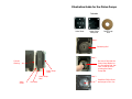
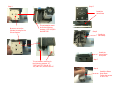
The enclosed Piston Pump Rebuild Kit is a direct replacement for use on
all piston motor pump assemblies in PACE power sources.
NOTE:
POTENTIAL SHOCK HAZARD - The following procedures are
to be performed by qualified service personnel only. Removal of
the power source panels exposes line voltage parts. Service
personnel must ensure that the AC Power Cord is disconnected
prior to disassembly.
Perform the following procedure to rebuild the pump.
1. Turn the Power Switch on the power source to the OFF (“O”) position.
2. Disconnect the power cord and all accessories (hand pieces, Tip &
Tool Stands etc.) from the power source.
3. Open the power source case. On PACE SensaTemp power sources,
use the applicable PACE Service Manual as a guide. Following are the
service manuals for SensaTemp systems.
SYSTEM
MANUAL PART NO.
MBT 101(A), MBT 201(A) ................ 5050-0340
MBT 250(A), MBT 220(A) ................ 5050-0352
4. Locate the Motor Pump Assembly. Note the position of each air hose
(2) connection to the motor pump assembly. Remove both air hoses.
5. You may find it necessary to remove the motor pump from its
mounted location to install the kit. If this is the case, take note of and
remove all mounting hardware and wiring attachments. Remove the
motor pump assembly from the power source.
6. Take note of the position of the ports. Refer to the different views in
the Illustration Section.
7. Begin the disassembly of the pump by completely removing the 4
mounting screws from the assembly then remove the following:
a. Piston Pump Plate
b. Lower Piston Pump Seal
c. Piston Pump Valve Body
d. Valve Sheet
e. Piston Pump Cylinder
f. Piston Pump Washer
g. Piston Pump Seal
NOTE:
If these parts are stuck to the assembly housing, you may find it
necessary to gently tap the side of the Pump Plate.
NOTE: There is an Orientation Indicator (notch) along one edge of
the Pump Plate and Pump Seal. It is not necessary that these
notches be in alignment with each other. Be sure to notice
the two different size alignment pins on the Piston Pump
Cylinder. The Piston Pump Valve Body and the Valve Sheet
have two different size holes, which must be aligned with the
correct pins on the Piston Pump Cylinder. If these parts are
not in alignment, the pump will not work.
8. Once the above items are removed, you can now remove the Piston
Pump Seal by carefully removing the Phillips Screw from the
connecting rod.
9. Be sure to inspect and clean all of the parts before reassembly.
10. Position the replacement parts (Piston Pump Seal, Valve Sheet, and
Lower Piston Pump Seal) together exactly as shown in the pictures.
11. Install the Pump Seal and Washer on the connecting rod with the large
black Phillips Screw. (MUST TORQUE TO 18 IN-LBS)
12. Carefully install the Piston Pump Cylinder. This will need to be oriented
to the proper position depending on the pump.
13. Install the Valve Sheet. Make sure that the alignment holes match up
properly to the Piston Pump Seal. (failure to do this could damage the
Valve body).
14. Next install the Piston Pump Valve Body along with the Piston Pump
Seal and the Piston Pump Plate.
15. Secure in position using the 4 mounting screws removed in step 7.
16. Torque these 4 mounting screws to 18 in. lbs. Be sure to snug the 4
screws up in a criss-cross pattern before torquing to the required
specification.
17. Install the Motor Pump Assembly (if removed in step 5) and assemble
the power source.
18. Connect the power cord and all accessories (handpieces, Tip & Tool
Stands etc.) removed in step 2 to the power source.
19. Turn the Power Switch to the ON (“1”) position and test system
operation.
NOTE: Torque values must be observed in order for successful pump
operation.
PACE Incorporated retains the right to make changes to specifications
contained herein at any time, without notice. Contact your local
authorized PACE Distributor or PACE Incorporated to obtain the latest
specifications.
The following are trademarks
Incorporated, MD, USA:
and/or
service
marks
of
PACE,
INSTACAL™, FUMEFLO™, HEATWISE™, PACEWORLDWIDE™,
PERMAGROUND™, POWERPORT™, POWERMODULE™, TEMPWISE™,
TIP-BRITE™, AUTO-OFF™, and TEKLINK™.
The following are registered trademarks and/or service marks of PACE
Incorporated, Annapolis Junction Maryland U.S.A.
ARM-EVAC®, FLO-D-SODR®, MINIWAVE®, PACE®, SENSATEMP®,
SNAP-VAC®, SODRTEK®, SODR-X-TRACTOR®, THERMOFLO®,
THERMOJET®, THERMOTWEEZ®, VISIFILTER®, THERMO-DRIVE®,
and TOOLNET®.
PACE products meet or exceed all applicable military and civilian
EOS/ESD, temperature stability and other specifications including MIL
STD 2000, ANSI/JSTD 001, IPC7711, and IPC A-610.
PACE, Inc.
9030 Junction Drive
Annapolis Junction, MD 20701
USA
Tel:
Fax:
(301) 490-9860
(301) 498-0193
PACE Europe
Sherbourne House
Sherbourne Drive
Tilbrook,Milton Keynes
MK7 8HX
United Kingdom
(44) 01908-277666
(44) 01908-277777
Piston Pump Rebuild Kit
PACE P/N 6993-0260-P1
Installation Instructions
Manual Number 5050-0539
For any questions regarding the following the following instructions,
contact your local authorized PACE dealer or contact PACE directly at:
Telephone (301) 490-9860, Fax (301) 498-0193
PACE, Inc.
9030 Junction Drive
Annapolis Junction, MD 20701
Illustration Guide for the Piston Pumps
Includes
Valve Sheet
Lower Piston
Pump Seal
Piston Pump
Seal
Step 1
Connecting Rod
Step 2
Be sure to fully seat the
Piston Pump Washer to
the Connecting Rod. Use
care in order to avoid
pinching the Piston
Pump Seal
Cylinder
Housing
Piston Pump
Plate
Lower Pump
Seal
Valve
Sheet
Valve Body
Step 3
Install the Phillips Screw
and torque to 18 in. lbs.
Step 5
Step 4
Install the
Valve Sheet
Be sure to orient the
Cylinder Housing for the
Correct System
This orientation would
be for the following
systems: MTS 300/350
and MBT 250
Step 6
Install the
Valve Body
Install the
Lower Piston
Pump Seal
This orientation would be for
the following systems: ST
75/ST 115, ST 125/145, ST
105, MBT 201, and MTS 200 SC
Step 7
Step 8
Install the Piston
Pump Plate.
Torque the screws
to 18 in. lbs.