1
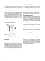
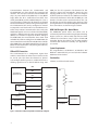
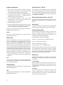
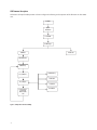
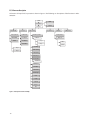
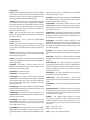
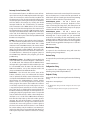
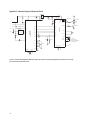
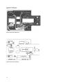
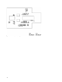
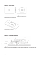
ADNK-3061 Optical Mouse Designer’s Kit Design Guide Introduction Introduction to ADNS-3060 Optical Mouse Sensor This design guide describes how a cost-effective combination USB‑PS/2 yet feature-rich optical mouse can be built using the Avago Technologies high performance ADNS-3060 optical mouse sensor and Cypress Semiconductor CY7C63743-PC USB microcontroller. The document starts with the basic operations of a computer mouse peripheral followed by an introduction to the ADNS-3060 optical mouse sensor and CY7C63743-PC USB microcontroller. A schematic of the ADNS-3060 optical mouse sensor to the CY7C63743-PC USB microcontroller buttons of a standard mouse is also shown in this document. The software section of this design guide describes the architecture of the firmware required to implement the USB and PS/2 mouse functions. Avago’s ADNS-3060 optical mouse sensor is used in this reference design as the primary navigation engine. This Optical Navigation Technology contains an Image Acquisition System, a Digital Signal Processor, and a four-wire serial port. The CY7C63743-PC periodically reads the ADNS-3060’s Delta_X and Delta_Y registers to obtain any horizontal and vertical motion information happening as a result of the mouse being moved. The four-wire synchronous serial port is used to set and read parameters in the ADNS-3060, and to read out the motion, (triangle)x and (triangle)y information. This motion information is reported to the PC updating the position of the cursor. The advantages of using the ADNS-3060 optical sensor are: best tracking accuracy, sensor programming flexibility via SPI port, and the automatic frame rate feature (1000fps to 6400fps). Furthermore, the ADNS-3060 sensor has excellent tracking performance on difficult surfaces such as wood and halftone surfaces. Additionally, the Burst mode is another special serial port operation mode which may be used to reduce the serial transaction time for three predefined operations: motion read, SROM download, and frame capture. Speed improvement is achieved by continuous data clocking to or from multiple registers during this operation. Optical Mouse Basics The optical mouse measureschanges in position by optically acquiring sequential surface images (frames), and mathematically determining the direction and magnitude of movement. The Z-wheel movement is done in the traditional method by decoding the quadrature signal generated by optical encoder. This design guide shows how to connect to and manage a standard configuration of mouse hardware, as well as handle the USB and PS/2 protocols. Each of these protocols provides a standard way of reporting mouse movement and button presses to the PC. Motion Read is activated by reading the Motion_Burst register. The ADNS-3060 will respond with the contents of the Motion, Delta_X, Delta_Y, SQUAL, Shutter_Upper, Shutter_Lower and Maximum_Pixel registers in that order. SROM download uses Burst Mode to load the Avago-supplied firmware file contents into the ADNS3060. The firmware file is an ASCII text file with each 2character byte (hexadecimal representation) on a single line. Frame Capture is a fast way to download a full array of pixel values from a single frame. To learn more about sensor’s technical information, please visit the Avago web site at http://www.semiconductor.Avago.com Mouse Optics Introduction to the CY7C63743-PC The of Z-wheel motion is detected using the traditional method by decoding the quadrature signal generated by optical encoder. Two phototransistors are connected in a sourcefollower configuration. An infrared LED shines, causing the phototran-sistors to turn on. In between the phototransistors and LED is a pinwheel that turns on the mouse ball rollers. The fan of this pinwheel is mechanically designed to block the infrared light such that the phototran-sistors are turned on and off in a quadrature output pattern. Every change in the phototransistor outputs represents a count of wheel movement. Comparing the last state of the optics to the current state derives direction information. As shown in Figure 1, traveling along the quadrature signal to the right produces a unique set of state transitions, and traveling to the left produces another set of unique state transitions. For a lower power system solution, using a mechanical z-wheel is recommended instead of a Z LED and Optical Encoder combination. The CY7C63743-PC is an 8-bit RISC microcontroller with an integrated USB Serial Interface Engine (SIE). The architecture executes general-purpose instructions that are optimized for USB applications. The CY7C63743-PC has a built-in clock oscillator and timers, as well as programmable drive strength, and pull-up resistors on each I/O line. High performance, low-cost human interface type computer peripherals can be implemented with a minimum of external components and firmware effort. Infrared LED Phototransistors Serial Peripheral Interface (SPI) The CY7C63743-PC provides a SPI compatible interface. The SPI circuit supports byte serial transfer in either Master or Slave mode. The integrated SPI circuit allows the CY7C63743-PC to communicate with an external SPI compatible hardware, in this case the ADNS-3060 sensor. Hardware Implementation The standard hardware to implement a mouse is shown in Figure 2. For X and Y movement, the optical mouse sensor is used. The Z wheel movement is detected by another set of optical encoder that outputs quadrature signals. For each button there is a switch that is pulled up internally by the built-in in pull up resistors. The D-line is pulled up via a 1.3k ohm resistor connected to the VREG pin. Firmware Configurable GPIO Q1.1 output Q1.3 output Figure 1. Optics Quadrature Signal Generation. Mouse Buttons Mouse buttons are connected as standard switches. These switches are pulled up by the pull up resistors inside the microcontroller. When the user presses a button, the switch will be closed and the pin will be pulled LOW to GND. A LOW state at the pin is interpreted as the button being pressed. A HIGH state is interpreted as the button has been released or the button is not being pressed. Normally the switches are debounced in firmware for 15–20 ms. In this reference design there are three switches: left, Z-wheel, and right. The reference firmware is configured to use the GPIO pins as shown in the schematic under Appendix A. However, it may be more optimal to use a different I/O configuration to meet the mechanical constraints of PCB design. The reference firmware is designed to be easily configured to another set of pin connections. This is accomplished through changes in the I/O definitions at the beginning of the adns- 3060.asm listing. The following statements are the pin definitions as they exist today. The firmware will use these definitions to read and configure the GPIO pins, without any other modifications. Communications between the CY7C63743-PC and the ADNS-3060 are done through the integrated SPI interface. The serial port cannot be activated while the chip is in power down mode (NPD low) or reset (RESET high). When the SPI is enabled thru P0.4 (NCS), P0.7 (SCLK), P0.6 (MISO), and P0.5 (MOSI) GPIO pins serve as special functions enabling the SPI interface to talk with the external hardware. (Sensor) During normal operation, the CY7C63743-PC SPI is always configured as a Master to output the serial clock on P0.7. So, the USB microcontroller always initiates communication. Data sent by the ADNS-3060 optical sensor is received on the P0.6 (MISO), and data is shifted out to the same sensor through P0.5 (MOSI). See schematic in Appendix A. When writing to the ADNS-3060, the microcontroller drives both SCLK and MOSI lines. When reading from the ADNS-3060, the microcontroller drives both SCLK and MOSI lines initially. After tSRAD delay, the ADNS-3060 will drive the data via MISO. The microcontroller is only driving the SCLK line ( for the serial interface). GPIO pins for PS/2 operation. The firmware for this reference design will automatically detect the host topology (USB or PS/2) at plug-in, and will configure itself for operation on that bus. If a USB host connection is detected, the firmware will enable the VREG pin, such that the 1.3k ohm resistor connected to the D- line, can be pulled up to 3.3V. Through this action, the host is able to recognize there is a lowspeed USB peripheral attached. These connections are shown in Figure 3 below. USB and PS/2 Connection PCs using Windows® 95/ Windows® 98/ Windows® NT/ Windows® 2000 with PS/2 port and standard 3-button USB mouse driver loaded. The CY7C63743-PC has a configuration register that switches control from the SIE to manual control on the D+ and D- pins. This allows the firmware to dynamically configure itself to operate as a USB or PS/2 mouse, allowing signal lines to be shared without using extra ADNK-3061 Designer’s Kit - Optical Mouse The ADNK-3061 optical mouse unit allows users to evaluate the performance of the Avago’s Optical Tracking Engine (sensor, lens, LED assembly clip, LED) over both a USB or PS/2 connection, using a Cypress enCoRe USB Controller. This kit also enables users to understand the recommended mechanical assembly. (See Appendices C, D, and E). System Requirements Functionality 3-button, scroll wheel combi-mouse. MISO VREG MOSI Avago ADNS-3060 optical mouse sensor SCLK NCS 1.3 k Ohm Z Optics Cypress CY7C63743A-PC enCoRe USB Controller Z LED Left Button USB/PS2 Interface Wheel Button Right Button Figure 2. CY7C63743-PC –ADNS-3060 Optical Mouse Hardware Block Diagram. D+/DSCLK/SDATA Operating (For PS/2 Mode) To Disassemble the ADNK-3061 Unit Step 1: Turn off the PC. The ADNK-3061 comprises of the plastic mouse casing, printed circuit board (PCB), lens, buttons, and USB cable. (See Figure 4.) Unscrewing the one screw located at the base of the unit can open the ADNK-3061 unit. Lifting and pulling the PCB out of the base plate can further disassemble the mouse unit. Step 2: Plug the mouse unit’s PS/2 connector into the PC’s PS/2 port. Step 3: Turn on the PC. All of the mouse buttons and scroll wheel will function exactly like a standard PS/2 mouse. Operating (For USB Mode) Hot pluggable with USB port. The PC does not need to be powered off when plugging or unplugging the evaluation mouse. While reassembling the components, please make sure that the Z height (Distance from lens reference plane to surface) is valid. Refer to Figure 5. Enabling the SROM The ADNS-3060 must operate from the externally loaded programming. This architecture enables immediate adoption of new features and improved performance algorithms. The external program is supplied by Avago as a file which may be burned into a programmable device. A microcontroller with sufficient memory may be used. On power-up and reset, the ADNS-3060 program is downloaded into volatile memory using the burst-mode procedure described in the Synchronous Serial Port section. The program size is 1986 x 8 bits. USB type-A connector For more information, please refer to the ADNS-3060 datasheet. Figure 3. USB and PS/2 peripheral connectors. Figure 4. Exploded view drawing of optical tracking engine with ADNS-3060 optical mouse sensor. Sensor Lens 2.40 mm (0.094 in) Object Surface Figure 5. Distance from lens reference plane to surface Regulatory Requirements Base Plate Feature – IGES File • Passes FCC B and worldwide analogous emission limits when assembled into a mouse with shielded cable and following Avago recommendations. The IGES file on the CD-ROM provides recommended base plate molding features to ensure optical alignment. This includes PCB assembly diagrams like solder fixture in assembly and exploded view, as well as solder plate. See Appendix D for details. • Passes IEC-1000-4-3 radiated susceptibility level when assembled into a mouse with shielded cable and following Avago recommendations. • Passes EN61000-4-4/IEC801-4 EFT tests when assembled into a mouse with shielded cable and following Avago recommendations. • UL flammability level UL94 V-0. • Provides sufficient ESD creepage/clearance distance to avoid discharge up to 15kV when assembled into a mouse according to usage instructions above. Below is the summary of the components contained in the ADNK-3061 Designer’s Kit. Reference Design Documentation – Gerber File The Gerber File presents detailed schematics used in ADNK-3061 in PCB layout form. See Appendix C for more details. Overall circuit A schematic of the overall circuit is shown in Appendix A of this document. Appendix B lists the bill of materials. Firmware Implementation The sensor technical information is contained in the ADNS-3060 Data Sheet. The firmware for this reference design is written in the Cypress assembly language. The following files are required to compile the mouse firmware 637xx.inc – the CY7C63743-PC I/O registers definition. USB Controller adns-3060.asm – main mouse firmware Technical information on the Cypress encore USB controller is contained in the CY7C63743-PC Data Sheet. The enclosed ADNK-3061 CD-ROM contains the development tools for the CY7C63743-PC. These tools will allow the designer to make changes and recompile the source code. To perform In-Circuit Emulation for easier debugging of new code development, contact Cypress to purchase the CY3654 Development Kit and the CY3654P05 Personality Board. Programming support and programmer adaptors for the Cypress CY7C63743-PC can be found through Cypress (CY3649-xxxV + CY3083-SC28 + CY3083-08) or through most 3rd party programming companies. macros.inc – general macros used with this design Sensor Lens The lens technical information is contained in the ADNS2120 Data Sheet. The flange on the standard ADNS-2120 lens is for ESD protection. LED Assembly Clip The information on the assembly clip is contained in the ADNS‑2220 Data Sheet. LED The LED technical information is contained in the HLMPED80-XX000 Data Sheet. ps2.inc – PS/2 interface constants usb.inc – USB interface constants adns-3060_srom_12.inc – SROM firmware At power up, the firmware examines the host interface and automatically determines if the mouse is plugged into a USB or a PS/2 host connection. After the interface type has been determined, the host firmware configures itself to operate on the detected interface. USB Interface All USB Human Interface Device (HID) class applications follow the same USB start-up procedure. The procedure is as follows: 1. Device Plug-in When a USB device is first connected to the bus, it is powered and running firmware, but communications on the USB remain non-functional until the host has issued a USB bus reset. 2. Bus Reset The pull-up resistor on D– notifies the hub that a low speed (1.5 Mbps) device has just been connected. The host recognizes the presence of a new USB device and initiates a bus reset to that device. 3. Enumeration The host initiates SETUP transactions that reveal general and device specific information about the mouse. When the description is received, the host assigns a new and unique USB address to the mouse. The mouse begins to respond, communicating with the newly assigned address, while the host continues to ask for information such as the device description, configuration description and HID report description. Using the returned information from the mouse, the host now knows the number of data endpoints supported by the mouse (2). At this point, the process of enumeration is completed. as the report format with the exception of the fourth byte, which is the wheel information. Appendix F of this document lists the USB Data Reporting Format. Notes: 1. idVendor should be changed to the value as supplied by the USBIF 2. idProduct should be assigned for specific product. 3. MaxPower value should be changed as per specific circuit’s current draw. 1. Device Plug-in 4. Post Enumeration Operation Once communication between the host and mouse is established, the mouse now has the task of sending and receiving data on the control and data endpoints. In this case, when the host configures endpoint 1, the mouse starts to transmit button and motion data back to the host when there is data to send. At any time, the peripheral may be reset or reconfigured by the host. USB Requests – Endpoint 0 Endpoint 0 acts as the control endpoint for the host. On power-up, endpoint 0 is the default communication channel for all USB devices. The host initiates ControlRead and Control-Write (see Chapter 8 of the USB specification) to determine the device type, as well as how to configure communications with the device. In this particular design, only Control-Read transactions are required to enumerate a mouse. For a list of valid requests see Chapter 9 of the USBG specification. In addition to the standard “Chapter 9” requests, a mouse must also support all valid HID class requests for a mouse. USB Requests – Endpoint 1 Endpoint 1 is the data transfer communications channel for mouse button, wheel, and movement information. Requests to this endpoint are not recognized until the host configures endpoint 1. Once this endpoint is enabled, then interrupt IN requests are sent from the host to the mouse to gather mouse data. When the mouse is left idle (i.e. no movement, no new button click, no wheel movement) the firmware will NAK requests to this endpoint. Data is only reported when there is a status change within the mouse. Two HID report formats are used in this design. The boot protocol, as defined by the HID specification, is the default report protocol that all USB enabled systems understands. The boot protocol has a three-byte format, and does not report wheel information. The HID report descriptor defines the report protocol format. This format is four bytes and is the same PS/2 Interface The host driver determines the PS/2 mouse start up sequence. However, to enable all PS/2 mice, a few standard commands must be sent. must be sent in order to enable all PS/2 mice. The mouse is the clock master on this bus. The host must request the mouse to clock data into itself. When a PS/2 mouse is first connected to the bus, it is powered and is running the system’s firmware. PS/2 communications generally begin with the host sending a RESET command to the mouse. The mouse will not report button, wheel, or movement back to the host until the ENABLE command is sent. The start-up sequence is dependant on the operating system the mouse is hooked up to. 2. Device Configuration During this time the host will set the standard PS/2 parameters such as scaling, resolution, stream mode; enabling stream mode for data reports. For a list of valid PS/2 commands the mouse recognizes, see Appendix G. 3. Wheel Enable (optional) Since the wheel is not part of the standard PS/2 specification, there is a sequence of commands that enable the wheel. Wheel-aware drivers, such as those for Microsoft and Linux operating systems will initiate this special sequence. After the following sequence of commands, the wheel report format is enabled. 0xF3, 0xC8 Set Sampling Rate 200 per second 0xF3, 0x64 Set Sampling Rate 100 per second 0xF3, 0x32 Set Sampling Rate 50 per second 0xF2, 0x03 Read Device Type returns a value of 0x03 After the Read Device Type command returns 0x03, indicating this is a Microsoft compatible three button wheel mouse, the wheel report format is enabled. See Appendix G for information on PS/2 standard and wheel reporting formats. 4. Post Start Up Operation After the streaming mode is set and data reports are enabled, the mouse will send button, movement, and optionally, wheel reports back to the host. Whenever the mouse has new data to send it will initiate a transfer to the host. USB Firmware Description A function call map for USB operation is shown in Figure 6. Following are descriptions of the functions in adns-3060. asm. DualMain System Initialization Load SROM GetMouseType USB Main PS2 Interface USB Initialization USBTaskLoop ReadMotionReg ProcessButtons ReadDeltaX ProcessOptics ReadDeltaY Load new mouse packet to EP1 buffer & enable EP1 Figure 6. USB Operation Function Call Map. Read Z Wheel Dual USB and PS2 Functions GetMouseType – called in dualMain when the mouse is first plugged into the PC. This routine returns the interface of the mouse. The following sequences are performed by the micro-controller to determine the mouse type. • Delay 50mS. • Initialize the PS2 BAT delay counter. • For a period of 2ms, poll the SCLK and SDATA lines every 10µs. If we get 4 samples in a row with nonzero data on either line, detect a PS2 interface. If 2mS expires, enable the USB pull up resistor and delay 500µS. • Poll the SCLK and SDATA lines indefinitely until a nonzero condition exists on either line. During this polling period, we begin to count down the PS2 BAT delay. • If SCLK(D+) is sampled high, detect a PS2 interface. If SDATA(D-) sampled high, disable the USB connect resistor and Delay 100µS. • If D+ and D- are both 0, detect a USB interface, else detect a PS2 interface. SPIInit – This routine is called in the try_download to enable the SPI interface. The CY7C63743-PC is always configured as a Master to drive the serial clock on P0.7. The clock is set to HIGH in idle state, and the SCLK frequency is set to send a bit rate of 1Mbit/s. SensorReset – This routine resets the serial interface and the ADND-3060 internal registers by generating a pulse on the RESET pin. LoadSROM – called in try_download after the initialization of the SPI interface. This routine is used to load the SROM (Shadow ROM) firmware into the ADNS-3060 optical sensor. It should be called after SensorReset. ProcessButtons – This routine is called within the infinite loop of usbTaskLoop and ps2TaskLoop. The state of the buttons is updated every one ms in the Dual1msTimer Interrupt Service Routine (ISR). This routine compares the current state of the buttons with their last state to detect any changes in the status. If the status of these buttons remains until the expiration of debounce timer (15ms), the new button state is confirmed. This routine will record the new button state in the [buttonValue] variable which will be reported to the host in the main loop. ReadProcessOptics – This routine returns any updates in the X, Y and Z-wheel motion information. The motion of the Z‑wheel is detected using the traditional method by decoding the quadrature signal generated by the phototransistors. The X and Y directions of the movement are obtained by calling the ReadDeltaX and ReadDeltaY routines. The X, Y, and Z-wheel movement is stored in the [xCount], [yCount], and [zCount] variables which will be sent to the host in the main routine. ReadMotionReg – Reads the ADNS-3060 Motion register. The data returned from this register will be used to determine if any motion has occurred or if any fault condition exists. ReadDeltaX – Reads the ADNS‑3060 Delta_X register for the X movement. Calls the ReadSPI routine to enable the SPI interface and perform reading operations through the four-wire serial interface. Any new X motion information is added to the [xCount] variable. ReadDeltaY – Reads the ADNS‑3060 Delta_Y register for the Y movement. Calls the ReadSPI routine to enable the SPI interface and perform reading operations through the four-wire serial interface. Any new Y motion information is added to the [yCount] variable. WriteSPI – Writes to the ADNS‑3060 register. A write operation consists of two bytes. The first byte contains the address (7 bits) and has “1” as its MSB. The second byte contains data. The microcontroller to drive both the SCLK and the MOSI lines. SPIWriteRoutine is called to carry the write operation. ReadSPI – Reads the desired ADNS-3060 registers. A read operation is composed of two parts. First, the microcontroller performs a write to the ADNS-3060, sending the address of the target register to be read. The microcontroller drives both the SCLK and MOSI lines. After tSRAD delay, the ADNS-3060 will drive the data via MISO. The microcontroller is only driving the SCLK line (outputs SCLK for the serial interface). SPIWriteRoutine is called to carry the write operation. SPIWriteRoutine – Writes the data to be transmitted onto the SPI pins. CheckProductID – This function checks the product ID of the sensor chip being used. The ID returned should match with the ADNS-3060’s ID. GetButtons – Returns the current state of the buttons. USB Functions usbMain – This routine initializes the USB related parameters and enables VREG to signal the host that the mouse has been connected. The program then goes to the usbTaskLoop . getDescriptor – This routine is entered when a GET DESCRIPTOR request is received from the host. This function decodes the descriptor request and sends the proper descriptor. usbTaskLoop – This function spins in an infinite loop waiting for an event that needs servicing. The ProcessButtons and ReadProcessOptics functions are called within this loop to retrieve any new motion or button information. The data received from these functions will be loaded into the endpoint 1 buffer to be sent to the host. setInterfaceIdle – This routine is entered whenever a SET IDLE request is received. See the HID specification for the rules on setting idle periods. This function sets the HID idle time. See the HID documentation for details on handling the idle timer. ep0SetupReceived – This routine is entered whenever a SETUP packet is received on endpoint 0. It parses the packet and calls the appropriate routine to handle the packet. ep0InReceived – This routine is entered whenever an IN packet is received on endpoint 0. ep0OutReceived – This routine is entered whenever an OUT packet is received on endpoint 0. setDeviceConfiguration – This routine is entered when a SET CONFIGURATION request has been received from the host. setDeviceAddress – This routine is entered whenever a SET ADDRESS request has been received. The device address change cannot take place until after the status stage of this no-data control transaction. So the address is saved and a flag is set to indicate that a new address was just received. The code that handles IN transactions will recognize this and set the address properly. setInterfaceProtocol – This routine is entered whenever a SET PROTOCOL request is received. This no-data control transaction enables boot or report protocol. getInterfaceReport – This routine is entered whenever a GET REPORT request is received. getInterfaceIdle – This routine is entered whenever a GET IDLE request is received. This function then initiates a control-read transaction that returns the idle time. See the HID class documentation for more details. getInterfaceProtocol – This routine is entered whenever a GET PROTOCOL request is received. This request initiates a control-read transaction that tells the host if the mouse is configured for boot or report protocol. See the HID class documentation for more details. getDeviceConfiguration – This routine is entered whenever a GET CONFIGURATION Request is received. This function then starts a control read transaction that sends the configuration, interface, endpoint, and HID descriptors to the host. requestNotSupported – Unsupported or invalid descriptor requests will cause this firmware to STALL these transactions. PS/2 Firmware Description A function call map for PS/2 operation is shown in Figure 7. The following are descriptions of the functions in Adns3060.asm ps2Main PS2BAT PS2 Initialization SetDefault ps2TaskLoop ps2SendNextByte ProcessOptics PS2DoCommand ProcessButtons HostRequestToSend ReadMotionReg PS2SendResponseByte PS2HostINhibit ReadDeltaX PS2Send ReadDeltaY Send_1 Read Z Wheel Send_0 PS2Send GetHostByte LoadMousePacket HostRequestToSend PS2Receive GetBit CheckWheel Send_1 Send_0 PS2ResetScaling PS2SetScaling PS2StatusRequest PS2SetStreamMode ResetInterval ResetWrapMode SetWrapMode SetRemoteMode ReadDeviceType Enable Disable SetDefault Resend Reset Figure 7. PS/2 Operation Function Call Map. 10 send0 PS/2 Functions PS2Main – Initializes the PS/2 related parameter to their default state, enables the serial interface and sends a BAT code (AAh followed by 00h) to the host. After the initialization, the program goes into the infinite PS2TaskLoop loop. PS2TaskLoop – This function spins in an infinite loop waiting for an event that needs servicing. The ProcessButtons and ReadProcessOptics functions are called within this loop to retrieve any new motion or button information. The data received from these functions will be loaded into the endpoint 1 buffer to be sent to the host. PS2BAT – delays for 500 milliseconds, then sends the AAh followed by 00h initialization string to the host for the PS/2 Basic Assurance Test. PS2SendResponseByte – Sends a response byte (ACK, ERROR, RESEND) to the host. PS2Send – This routine sends a byte to the host according to the standard PS/2 protocol. This routine calls send_0 and send_1 routines that shift the bits out serially over the PS/2 interface. PS2Receive – This routine receives a byte from the host according to the standard PS/2 protocol. This routine calls the GetBit function to clocks each bit in. PS2Resend – A copy of the last transmission is always left intact in the message buffer. To re-send it, this routine simply resets the message length. PS2SetDefault – This routine is called in response to a SET DEFAULT command from the host. It then sets the mouse parameters to the default settings. PS2DisableMouse – Disables the mouse. PS2EnableMouse – Enables the mouse. PS2SetSampleRate – This routine is called in response to a SET SAMPLE RATE command from the host. It then verifies that the requested sample rate is valid and sets the sample rate for the mouse. Valid sample rates are defined in the PS/2 Mouse specification. PS2ReadDeviceType – This routine is called in response to a READ DEVICE TYPE request from the host. This mouse always sends a 0x00 in response to this request. PS2SetRemoteMode – This routine is called in response to a SET REMOTE MODE command from the host. The PS/2 mode is then set to remote mode. PS2SetWrapMode – This routine is called in response to a SET WRAP MODE command from the host. It then sets the mouse mode to wrap mode. See the PS/2 specification for more details on wrap mode. PS2ResetWrapMode - This routine is called in response to a RESET WRAP MODE command from the host. The mode is then reset to the previous mode. According to the IBM PS/2 speci11 fication, if stream mode is enabled, the mouse is disabled when the wrap mode is reset. PS2ReadData – This routine is called in response to a READ DATA command from the host. This routine then sends a mouse packet in response to the command. PS2SetStreamMode – This routine is called in response to a SET STREAM MODE command from the host. Stream mode is then enabled. See the PS/2 specification for more information about stream mode. PS2StatusRequest – This routine is called in response to a STATUS REQUEST command from the host. A three byte report is sent to the host in response to this request. See the PS/2 mouse specification for more details. PS2SetResolution – This routine is called in response to a SET RESOLUTION command from the host. Set Resolution is a two byte command; the 2nd byte being the resolution itself. This routine is called after reception of the first byte, and so does nothing by itself. PS2SetScaling – This routine is called in response to a SET SCALING command from the host. Scaling then changes to 2:1. PS2ResetScaling – This routine is called in response to a RESET SCALING command from the host. The scaling is then reset back to 1:1. PS2GetHostByte(void) – This routine checks to see if the host is requesting to send data, and if so, it clocks in a data byte from the host. The function returns the received byte in the accumulator and implicitly clears the carry to 0 if the reception occurred without errors. PS2DoCommand – This routine dispatches the received PS/2 command byte to the proper handler. LoadMousePacket – This routine formats a mouse packet according to the PS/2 Mouse specification and loads it to the buffer. PS2SendNextByte – This routine sends the next byte in buffer to the host. ResetMouseReportInterval – This routine resets the mouse report interval to the value last sent by the host. The report interval is counted down in the main loop to provide a time base for sending mouse data packets. CheckWheel – This function checks whether the proper sequence of commands have been issued by the host to enable the wheel of the mouse. The sequence is three consecutive setting rate commands of 200, 100 and 80 reports per second. send_1 – sends a PS/2 1 bit send_0 – sends a PS/2 0 bit GetBit – receives a PS/2 bit from the host Interrupt Service Routines (ISR) The CY7C63743-PC features 12 different sources of interrupts. There are only four ISRs implemented in this application. If an interrupt is enabled and the conditions for the interrupts are met, the microcontroller will generate an interrupt. Upon servicing the interrupt, the hardware will first disable all interrupts by clearing the Global Interrupt Enable bit. This is followed by an automatic CALL instruction to the ROM address of the interrupt being serviced in the Interrupt Vector. The instruction in the Interrupt Vector is typically a JMP instruction to the Interrupt Service Routine (ISR). A RETI or RET instruction at the end of the ISR brings the program counter (PC) back to the location prior to the interrupt (POR and USB Bus Reset are exceptions). DualMain – When power is first applied to the CY7C63743PC, a Power On Reset (POR) occurs; the microcontroller starts executing code from address 0x00. This is a JMP instruction to the DualMain routine. This routine initializes the program stack pointer (PSP), data stack pointer (DSP), ram variables, and the GPIO pins. This routine calls GetMouseType which returns the interface of the mouse. If a USB interface is detected, the program jumps to the usbMain loop. Otherwise, the program goes to the ps2Main loop. DualUsbBusReset_ps2Error – The USB-PS2 Interrupt Mode bit in the USB Status and Control Register is defaulted to “0”, or USB mode. This indicates that the USB Bus Reset interrupt will be generated if the SE0 condition (D+ and D- are both LOW) exists for 256us. This ISR enables the USB Device Address, sets up the endpoint modes and jumps to usbMain for the USB initialization. Dual1msTimer – This ISR reads the current status of the buttons. Therefore, every one millisecond the button state is updated; the button status information will be used by the ProcessButtons function at a later time. This ISR maintains the dualInterface1ms counter variable which is used as a 1ms timing reference in other parts of the program. This routine also handles the entrance or exit from suspend. The mouse will prepare to enter a suspend (low power) state if there is no bus activity in 3ms. If the mouse is configured for remote wakeup, the Bus Reset and wakeup interrupts are enabled prior to suspending the chip. The program then enters a suspended state, and will wake at least as often as the wakeup timer interrupts or as a result of the USB Bus Reset interrupt. Each time the chip wakes up due to the wake up timer interrupt, the state of the buttons is examined by the GetButtons function. If a change in the button state has occurred, the mouse will generate a resume signal to the host and exit the ISR. If the device is not enabled for remote wakeup, only the USB bus reset interrupt is enabled, and the part is suspended. Only a Bus Reset can wake up the chip. If the resume was due to bus activity, 12 the firmware returns to the main loop. If the resume was due to a button press, a K state is driven upstream for 14 milliseconds prior to returning to the main loop. Moving the mouse will not wake the suspended system. DualUsbEndpoint0_ps2Error – This ISR is entered upon receiving an Endpoint 0 interrupt. Endpoint 0 interrupts occur during the Setup, data, and status phases of a control transfer. This ISR handler jumps to the proper routine to handle one of these phases. DualUsbEndpoint1_ps2Error – This ISR is entered upon receiving an Endpoint 1 interrupt. If the ACK bit is set, indicating that a mouse packet was just transmitted to the host successfully, the SIE automatically sets the endpoint mode to NAK_IN mode, and the data toggle bit is flipped for the next transaction. The data toggle bit should never be toggled if the interrupt was a result of a NAK transaction. Manufacturer String A request for the manufacturer string will return the following string: “Avago Mouse”. Product String A request for the product string will return the following string: “ADNS-3060 Mouse”. Configuration String A request for the configuration string will return the following string: “HID-Compliant Mouse”. Endpoint 1 String A request for the endpoint string will return the following string: “Endpoint 1 Interrupt Pipe”. Notes: 1. The Manufacturer String should be changed to the name of your company. 2. The Product String should be changed to your product’s name. Appendix A: Schematic Diagram of the Overall Circuit LP2950ACZ-3.3 3 Vin Vo 1 2 0.1 F 4.7 F 0.1 F 17 14 11 GND GND QA SHLD Vcc QB 17 18 D- P0.7 Vreg P0.6 P0.5 P1.7 P1.5 240Ω 7 P0.4 P0.2 P0.3 P1.4 Z LED P1.0 P1.2 P1.1 VSS XTALOUT 21 3 22 2 23 4 24 1 3 4 5 6 20 9 10 K 6 10 K 7 20 KΩ R HLMP-ED80 187Ω 1/8 W SURFACE GND LED_CTRL SCLK MISO MOSI NCS REFB REFC RESET NPD OSC_IN GUARD 20 KΩ OSC_OUT L M ADNS-2120 Lens Internal Image Sensor Buttons 11 18 NC 1.3 KΩ 19 D+ NC 15 D- Vpp V DD V DD GND NC 16 D+ 16 CYPRESS CY7C63743-PC 10 Vcc Vcc Vo 15 ADNS-3060 0.1 F 4.7 F 0.1 F GND OPTP 5 1K MMBT2222A 14 2.2 F 13 10 9 24 MHz Ceramic Resonator Murata CSALS24M0X53-B0 TDK FCR24.0M2G 8 12 Vo 3.3V 20 XTALIN 13 12 6 MHz (Optional) Figure A1. Circuit-level block diagram for ADNK-3061 designer’s kit optical mouse using the Avago ADNS-3060 optical mouse sensor and Cypress CY7C63743-PC enCoRe USB Controller. 13 Appendix B: Bill of Materials for Components Shown on Schematic Part Type Footprint Quantity Designators 0R (Jumper) AXIAL 0.35 2 R1, R3 0R (Jumper) 0805_CUS 6 R6, R11, R12, R13, R14, R15 Ceramic cap. 0.1uF (104) 0805_CUS 4 C1, C3, C6, C7 Chip resistor 10K 1% 0805_CUS 2 R7, R9 Resistor 187R 1% 0.125W AXIAL0.3 1 R2 Chip resistor 1K 1% 0805_CUS 1 R5 Chip resistor 1K3 1% 0805_CUS 1 R16 Chip resistor 20K 1% 0805_CUS 2 R8, R10 Chip resistor 240R 1% 0805_CUS 1 R4 Resonator 24MHz XTAL4 1 X1 Transistor 2N2222 TO92C 1 Q3 Ceramic cap. 2.2uF 16V 1206 1 C5 Tant. cap. 4.7uF 16V 1206 2 C2, C4 Resonator 6MHz (optional) XTAL4 1 X2 ANDS-3060 image sensor DIP1x2MM 1 U1 Micro-controller CY7C63743 DIP24-300 1 U2 HLMP-ED80-PS000 LED 1 D2 LED Clip clip 1 D2* Voltage Regulator LP2950ACZ-3.3 TO92C 1 Q1 Molex-5P latch / 2.54mm pitch MOLEX5P /0.1 1 J1 Mouse button switch SW-SPDT-ZIPPY 3 S1, S2, S3 XX (Reserved) 0805_CUS 2 R17, R18 Z-ENCODER ZDET 1 Q2 Z-LED ZLED 1 D1 14 Appendix C: PCB Layout Figure C1. PCB Schematic (Bottom Layer). Figure C2. PCB Schematic (Top Overlay). 15 Figure C3. PCB Schematic (Bottom Overlay). 16 Appendix D: Base Plate Feature Figure D1. Bottom, top and side view of base plate. Figure D2. Overall top view of base plate. Appendix E: Sectional View of PCB Assembly Clip LED Sensor PCB Lens/Light Pipe Base Plate Surface Figure E1. Sectional view of PCB assembly highlighting all optical mouse components (optical mouse sensor, clip, lens, LED, PCB, and base plate). 17 Appendix F: USB data reporting format The USB report has two formats, depending whether boot or report protocol is enabled. The following format is the boot protocol, and is understood by a USB aware BIOS. Bit 7 Bit 0 Byte 0 0 0 0 0 0 Middle Right Left Byte 1 X X X X X X X X Byte 2 Y Y Y Y Y Y Y Y The following is the USB report protocol format allowing the additional wheel movement information in the fourth byte. When the wheel is moved forward, the fourth byte reports a 0x01. When moved backward, the fourth byte reports 0xFF. When the wheel is idle, then this byte is assigned 0x00. Bit 7 Bit 0 Byte 0 0 0 0 0 0 Middle Right Left Byte 1 X X X X X X X X Byte 2 Y Y Y Y Y Y Y Y Byte 3 R R R R R R R F/R Appendix G: PS/2 reporting format The PS/2 portion of the firmware handles the following requests and commands listed in the table below. Hex Code Command Action 0xFF Reset Resets mouse to default states 0xFE Resend Resends last data to host 0xF6 Set Default Sets mouse to use default parameters 0xF5 Disable Disables the mouse 0xF4 Enable Enables the mouse 0xF3 Set Sampling Rate Set sampling rate to 10,20,40,60,80,100,200/second 0xF2 Read Device Type Returns 0x00 to host, indicating the device is a mouse 0xF0 Set Remote Mode Sets remote mode so data values are only reported after a read data command 0xEE Set Wrap Mode Set wrap mode until 0xFF or 0xEC is received 0xEC Reset Wrap Mode Reset to previous mode of operation 0xEB Read Data Responds by sending a mouse report packet to host 0xEA Set Stream Mode Sets stream mode 0xE9 Status Request Returns current mode, en/disabled, scaling, button, resolution, and sampling rate information to the host. 0xE8 Set Resolution Sets resolution to 1,2,4,8 counts/mm 0xE7 Set Scaling 2:1 Sets scaling to 2:1 0xE6 Reset Scaling Resets scaling to 1:1 0xAA Completion Code Command completion code 0xFA Peripheral ACK Sent to acknowledge host requests 18 The PS/2 specification calls out the following default mouse report format. Byte 0 is the button data (1=pressed, 0=released), X and Y optics sign bits, and X and Y overflow bits. Byte 1 is the X optics data in 2’s complement format. Byte 2 has the Y optics data in 2’s complement format. At reset or power-on the standard PS/2 reporting format is enabled. Bit 7 Bit 0 Byte 0 Y Overflow X Overflow Y sign X sign Reserved 0 Reserved 0 Right button Left button Byte 1 X X X X X X X X Byte 2 Y Y Y Y Y Y Y Y After the following sequence of commands, the wheel report format is enabled. 0xF3, 0xC8 Set Sampling Rate 200 per second 0xF3, 0x64 Set Sampling Rate 100 per second 0xF3, 0x32 Set Sampling Rate 50 per second 0xF2, 0x03 Read Device Type returns a value of 0x03 After the Read Device Type command returns 0x03 to indicate that this is a Microsoft compatible three button-wheel mouse, the wheel report format is enabled. After this initialization sequence, the PS/2 wheel reporting format is enabled. The fourth byte represents the wheel data. This byte is assigned 0x01 for forward wheel movement and 0xFF for backward wheel movement. When the wheel is idle, this value is 0x00. Bit 7 Bit 0 Byte 0 Y Overflow X Overflow Y sign X sign Always 1 Middle ButtonRight button Left button Byte 1 X X X X X X X X Byte 2 Y Y Y Y Y Y Y Y Byte 3 Wheel* Wheel* Wheel* Wheel* Wheel* Wheel* Wheel* Wheel* The PS2 data transmission according to the PS/2 Hardware Interface Technical Reference including eleven bits for each byte sent. The bits are sent in the following order with data valid on the falling edge of the clock. See the PS/2 Hardware Interface Technical Reference manual for timing information. Start Bit Data Data Data Data Data Data Data Data Bit 7 (Always 0)Bit 0Bit 1Bit 2Bit 3Bit 4Bit 5Bit 6Bit 6 19 Odd Parity Bit Stop Bit (Always 1) Appendix H: Kit Components Kit Components The designer’s kit contains components as follows: Part Number Description Name Quantity ADNS-3060 Optical Mouse Sensor Sensor 5 ADNS-2120 Round Lens Plate Lens 5 ADNS-2120-001 Trim Lens Plate Lens 5 ADNS-2220 LED Assembly Clip (Black Clip) LED Clip 5 ADNS-2220-001 LED Assembly Clip (Transparent) LED Clip 5 HLMP-ED80-XX000 639 nm T 1 _ (5 mm) Diameter LED LED 5 ADNK-3061 CD Includes Documentation and Support Files for ADNK-3061 and CY7C63743-PC 1 Documentation a. ADNS-3060 Data Sheet b. CY7C63743-PC Data Sheet c. ADNS-2120 Data Sheet d. ADNS-2220 Data Sheet e. HLMP-ED80-XX000 LED Data Sheet f. AN 5035 – PCB Mounting Method for ADNS-3060 Optical Sensor g. AN 5034 – ADNS-3060 Power Saving Methodology h. AN 5036 – ADNS-3060 Eye Safety Calculations Hardware Support Files a. ADNK-3061 BOM List b. ADNK-3061 Schematic c. 3D Model IGES Files d. Gerber File Software Support Files a. Microcontroller Firmware Cypress LAB™ Documentation and Support Files a. CY Debugger b. CYASM Assembler Software c. Code Examples d. User Manual ADNK-3061 Mouse High Performance Reference Design Mouse For product information and a complete list of distributors, please go to our web site: www.avagotech.com Avago, Avago Technologies, and the A logo are trademarks of Avago Technologies in the United States and other countries. Data subject to change. Copyright © 2005-2008 Avago Technologies. All rights reserved. Obsoletes 5989-0690EN AV02-1034EN - September 8, 2008 Optical Mouse 1 Mouser Electronics Authorized Distributor Click to View Pricing, Inventory, Delivery & Lifecycle Information: Avago Technologies: ADNK-3061