1
OneWireless
XYR 6000 Pressure Transmitter
R120 User's Manual
34-XY-25-15
Revision 9
January 2012
Notices and Trademarks
Copyright 2008-10 by Honeywell International Inc.
Revision 9 January 2012
While this information is presented in good faith and believed to be accurate, Honeywell disclaims the implied
warranties of merchantability and fitness for a particular purpose and makes no express warranties except as may
be stated in its written agreement with and for its customers.
In no event is Honeywell liable to anyone for any indirect, special or consequential damages. The information and
specifications in this document are subject to change without notice.
Honeywell, PlantScape, Experion PKS, and TotalPlant are registered trademarks of Honeywell International Inc.
Other brand or product names are trademarks of their respective owners.
Honeywell Process Solutions
1860 West Rose Garden Lane
Phoenix, Arizona 85027
ii
OneWireless XYR 6000 Pressure Transmitter R120 User's Manual
Revision 9
January 2012
About This Document
This document describes preparation, operation and maintenance of the XYR 6000 Wireless Pressure Transmitters.
Mounting, installation and wiring are covered in other documents.
Honeywell does not recommend using devices for critical control where there is a single point of failure or where
single points of failure result in unsafe conditions. OneWireless is targeted at open loop control, supervisory
control, and controls that do not have environmental or safety consequences. As with any process control solution,
the end-user must weigh the risks and benefits to determine if the products used are the right match for the
application based on security, safety, and performance. Additionally, it is up to the end-user to ensure that the
control strategy sheds to a safe operating condition if any crucial segment of the control solution fails.
Revision Information
Document Name
Document ID
Revision
Number
Publication Date
XYR 6000 Pressure Transmitter R120 User's Manual
34-XY-25-15
10KPSI and IS battery holder
8
November 2010
O’Ring part number (K7) update
9
January 2012
References
The following list identifies all documents that may be sources of reference for material discussed in this publication.
Document Title
XYR 6000 Transmitters Quick Start Guide
Getting Started with Honeywell OneWireless Solutions
OneWireless Wireless Builder User’s Guide
OneWireless Builder Parameter Reference
Revision 9
January 2012
OneWireless XYR 6000 Pressure Transmitter R120 User's Manual
iii
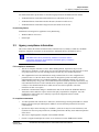
Support and contact info
See back page for all country specific contact details
World Wide Web
Honeywell Solution Support Online:
http://www.honeywell.com/ps/hfs
Elsewhere
Call your nearest Honeywell office.
Training Classes
Honeywell Automation College:
http://www.automationcollege.com
iv
OneWireless XYR 6000 Pressure Transmitter R120 User's Manual
Revision 9
January 2012
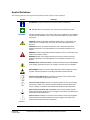
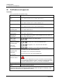
Symbol Definitions
The following table lists those symbols used in this document to denote certain conditions.
Symbol
Definition
ATTENTION: Identifies information that requires special consideration.
TIP: Identifies advice or hints for the user, often in terms of performing a task.
CAUTION
Indicates a situation which, if not avoided, may result in equipment or work (data) on
the system being damaged or lost, or may result in the inability to properly operate
the process.
CAUTION: Indicates a potentially hazardous situation which, if not avoided, may
result in minor or moderate injury. It may also be used to alert against unsafe
practices.
CAUTION symbol on the equipment refers the user to the product manual for
additional information. The symbol appears next to required information in the
manual.
WARNING: Indicates a potentially hazardous situation, which, if not avoided, could
result in serious injury or death.
WARNING symbol on the equipment refers the user to the product manual for
additional information. The symbol appears next to required information in the
manual.
WARNING, Risk of electrical shock: Potential shock hazard where HAZARDOUS
LIVE voltages greater than 30 Vrms, 42.4 Vpeak, or 60 VDC may be accessible.
ESD HAZARD: Danger of an electro-static discharge to which equipment may be
sensitive. Observe precautions for handling electrostatic sensitive devices.
Protective Earth (PE) terminal: Provided for connection of the protective earth
(green or green/yellow) supply system conductor.
Functional earth terminal: Used for non-safety purposes such as noise immunity
improvement. NOTE: This connection shall be bonded to Protective Earth at the
source of supply in accordance with national local electrical code requirements.
Earth Ground: Functional earth connection. NOTE: This connection shall be
bonded to Protective Earth at the source of supply in accordance with national and
local electrical code requirements.
Chassis Ground: Identifies a connection to the chassis or frame of the equipment
shall be bonded to Protective Earth at the source of supply in accordance with
national and local electrical code requirements.
continued
Revision 9
January 2012
OneWireless XYR 6000 Pressure Transmitter R120 User's Manual
v
Symbol
Description
®
The Factory Mutual Approval mark means the equipment has
been rigorously tested and certified to be reliable.
The Canadian Standards mark means the equipment has been
tested and meets applicable standards for safety and/or
performance.
The Ex mark means the equipment complies with the requirements
of the European standards that are harmonized with the 94/9/EC
Directive (ATEX Directive, named after the French "ATmosphere
EXplosible").
For radio equipment used in the European Union in accordance
with the R&TTE Directive the CE Mark and the notified body (NB)
identification number is used when the NB is involved in the
conformity assessment procedure. The alert sign must be used
when a restriction on use (output power limit by a country at certain
frequencies) applies to the equipment and must follow the CE
marking.
The C-Tick mark is a certification trade mark registered to ACMA
(Australian Communications and Media Authority) in Australia under
the Trade Marks Act 1995 and to RSM in New Zealand under
section 47 of the NZ Trade Marks Act. The mark is only to be used
in accordance with conditions laid down by ACMA and RSM. This
mark is equal to the CE Mark used in the European Union.
N314 directly under the logo is Honeywell’s unique supplier
identification number.
vi
OneWireless XYR 6000 Pressure Transmitter R120 User's Manual
Revision 9
January 2012
Revision 9
January 2012
OneWireless XYR 6000 Pressure Transmitter R120 User's Manual
vii
Contents
Support and contact info........................................................................................................................iv
1.
INTRODUCTION .................................................................................................... 1
1.1
Purpose ..........................................................................................................................................1
1.2
Scope..............................................................................................................................................1
1.3
OneWireless network overview ...................................................................................................1
1.4
About the transmitter....................................................................................................................1
2.
SPECIFICATIONS ................................................................................................. 3
2.1
European Union Usage.................................................................................................................3
2.2
Certifications and approvals........................................................................................................4
Transmitter .............................................................................................................................................................4
Provisioning Device ................................................................................................................................................5
2.3
Agency compliance information..................................................................................................5
FCC compliance statements ..................................................................................................................................5
IC compliance statements ......................................................................................................................................5
Radio Frequency (RF) statement ...........................................................................................................................6
European Union restriction .....................................................................................................................................6
Japanese Restrictions ............................................................................................................................................6
2.4
Honeywell European (CE) Declaration of Conformity (DoC) ....................................................7
For more information about the R&TTE Directive...................................................................................................9
2.5
IECEx Conditions of Certification................................................................................................9
ATEX Conditions for Safe Use ...............................................................................................................................9
3.
PREPARATION ................................................................................................... 10
3.1
Installation ...................................................................................................................................10
3.2
Configuration...............................................................................................................................10
3.3
Connecting to network ...............................................................................................................10
3.4
Calibrating the transmitter .........................................................................................................10
Overview ..............................................................................................................................................................10
Calibrate zero .......................................................................................................................................................10
4.
FUNCTION BLOCKS........................................................................................... 12
4.1
Introduction .................................................................................................................................12
4.2
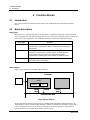
Block description ........................................................................................................................12
Block types ...........................................................................................................................................................12
Block diagram.......................................................................................................................................................12
4.3
Parameter details ........................................................................................................................13
Revision 9
January 2012
OneWireless XYR 6000 Pressure Transmitter R120 User's Manual
ix
Contents
5.
OPERATION ........................................................................................................ 14
5.1
Overview ......................................................................................................................................14
Display modes ..................................................................................................................................................... 14
Authentication Device .......................................................................................................................................... 14
5.2
Transmitter connection status...................................................................................................15
5.3
Transmitter PV display ...............................................................................................................16
5.4
Transmitter quick view of parameters ......................................................................................20
5.5
Transmitter menu ........................................................................................................................21
Menu tree............................................................................................................................................................. 21
5.6
Authentication device menus ....................................................................................................22
Overview .............................................................................................................................................................. 22
Main menu ........................................................................................................................................................... 22
Security and Node Deployment ........................................................................................................................... 23
Device Local Configuration .................................................................................................................................. 25
Read Node Information ........................................................................................................................................ 26
Advanced Options................................................................................................................................................ 28
6.
MAINTENANCE/REPAIR .................................................................................... 29
6.1
Introduction .................................................................................................................................29
6.2
Preventive maintenance .............................................................................................................29
6.3
Inspecting and cleaning barrier diaphragms ...........................................................................29
Tools required ...................................................................................................................................................... 29
Procedure ............................................................................................................................................................ 30
Torque ratings ...................................................................................................................................................... 31
6.4
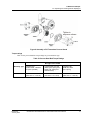
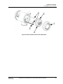
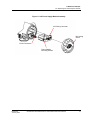
Replacing sensor module ..........................................................................................................32
Tools required ...................................................................................................................................................... 32
Procedure ............................................................................................................................................................ 32
6.5
Replacing batteries .....................................................................................................................34
When to replace................................................................................................................................................... 34
Tools required ...................................................................................................................................................... 34
Procedure ............................................................................................................................................................ 34
6.6
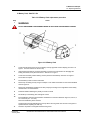
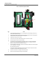
Replacing 24V external power module .....................................................................................36
When to replace................................................................................................................................................... 36
Tools required ...................................................................................................................................................... 36
Procedure ............................................................................................................................................................ 36
6.7
Replacing antenna ......................................................................................................................39
Tools required ...................................................................................................................................................... 39
Procedure ............................................................................................................................................................ 39
6.8
Parts .............................................................................................................................................42
Transmitter body .................................................................................................................................................. 42
Meter body ........................................................................................................................................................... 43
6.9
x
Dimension drawings ...................................................................................................................48
OneWireless XYR 6000 Pressure Transmitter R120 User's Manual
Revision 9
January 2012
Contents
Tables
Tables
Table 1 Calibrate zero .................................................................................................................................11
Table 2 Transmitter connection status ........................................................................................................15
Table 3 PV engineering units ......................................................................................................................16
Table 4 PV status ........................................................................................................................................17
Table 5 Device status ..................................................................................................................................17
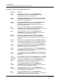
Table 6 Menu tree........................................................................................................................................21
Table 7 Buttons for Device Local Configuration ..........................................................................................25
Table 8 Advanced Options ..........................................................................................................................28
Table 9 Inspecting and Cleaning Barrier Diaphragms.................................................................................30
Table 10 Process Head Bolt Torque Ratings ..............................................................................................31
Table 11 Sensor module replacement.........................................................................................................32
Table 12: IS Battery Pack replacement procedure......................................................................................35
Table 13 24V External power module .........................................................................................................38
Table 14 Antenna replacement procedure ..................................................................................................40
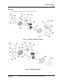
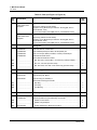
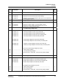
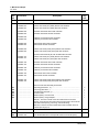
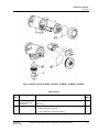
Table 15 Parts (see Figure 13, Figure 14)..................................................................................................44
Table 16 Parts .............................................................................................................................................47
Table 17 Drawing numbers for DP models STDW924, STDW930, STDW974 ..........................................48
Table 18 Drawing numbers for DHGP models STGW944, STGW974 .......................................................48
Table 19 Drawing numbers for GP/AP models STGW94L, STGW97L, STGW98L, STAW94L, STGW99L..48
Revision 9
January 2012
OneWireless XYR 6000 Pressure Transmitter R120 User's Manual
xi
Contents
Figures
Figures
Figure 1 XYR 6000 Functional Diagram .......................................................................................................2
Figure 2 Block Diagram ...............................................................................................................................12
Figure 3 Main menu.....................................................................................................................................22
Figure 4 Security and Node Deployment.....................................................................................................23
Figure 5 Device Local Configuration screen................................................................................................25
Figure 6 Read Node Information .................................................................................................................26
Figure 7 Advanced Options .........................................................................................................................28
Figure 8 Assembly of DP Transmitter Process Heads ................................................................................31
Figure 9 Sensor module removal and replacement ....................................................................................33
Figure 10: IS Battery Pack...........................................................................................................................35
Figure 11 24V Power Supply Module Assembly ........................................................................................37
Figure 12 Antenna replacement ..................................................................................................................41
Figure 13 STDW924, STDW930, STDW974..............................................................................................43
Figure 14 STGW944, STGW974 .................................................................................................................43
Figure 15 GP/AP models STGW94L, STGW97L, STGW98L, STGW99L, STAW94L................................47
xii
OneWireless XYR 6000 Pressure Transmitter R120 User's Manual
Revision 9
January 2012
1. Introduction
1.1. Purpose
1. Introduction
1.1
Purpose
This manual describes the Honeywell OneWireless XYR 6000 Pressure Transmitter function, operation
and maintenance.
1.2
Scope
The manual includes:
1.3
Details of topics that relate uniquely to the Honeywell XYR 6000 Pressure Transmitter,
This manual does not cover installation, mounting, or wiring. See XYR 6000 Transmitter Quick Start
Guide (document 34-XY-25-21).
OneWireless network overview
OneWireless is an all digital, serial, two-way communication mesh network that interconnects industrial
field sensors to a central system.
OneWireless has defined standards to which field devices and operator stations communicate with one
another. The communications protocol is built as an "open system" to allow all field devices and
equipment that are built to OneWireless standard to be integrated into a system, regardless of the device
manufacturer. This interoperability of devices using OneWireless technology is to become an industry
standard for automation systems.
1.4
About the transmitter
The XYR 6000 Pressure Transmitter is furnished with OneWireless interface to operate in a compatible
distributed OneWireless system. The transmitter will interoperate with any OneWireless-registered device.
The transmitter includes OneWireless electronics for operating in a 2.4GHz network. It features function
block architecture.
The XYR 6000 Pressure Transmitter comes in a variety of models for measurement applications involving
one of these basic types of pressure:
Differential pressure,
Gauge pressure,
Absolute pressure.
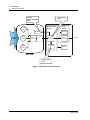
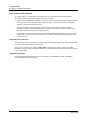
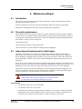
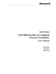
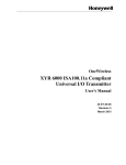
The transmitter measures the process pressure and transmits the measured value as a digital output signal
in user-configured engineering units. Its major components are electronics housing and a meter body as
shown in Figure 1 (a typical differential pressure model transmitter).
The XYR 6000 transmits its output in a digital OneWireless protocol format for direct digital
communications with systems.
The Process Variable (PV) is available for monitoring and alarm purposes. Available PV update rates: 1, 5,
10, 30 seconds and are set on Wireless Builder. Slower update rates extend battery life. The meter body
temperature is also available as a secondary variable for monitoring. Figure 1 shows a block diagram of
the XYR 6000 Pressure transmitter’s operating functions.
Revision 9
January 2012
OneWireless XYR 6000 Pressure Transmitter R120 User's Manual
1
1. Introduction
1.4. About the transmitter
Configuration
Data
Factory
Characterization
Data
Measurement
Board
DP or AP
Sensor
EEPROM
Pressure
Input
SP
Sensor
Multiplexer
A/D
EEPROM
Microprocessor
Microprocessor
EEPROM
Temp
Sensor
Radio
Board
Antenna
Battery
Meter Body
Electronics Housing
Configuration
Data
Figure 1 XYR 6000 Functional Diagram
2
OneWireless XYR 6000 Pressure Transmitter R120 User's Manual
Revision 9
January 2012
2. Specifications
2.1. European Union Usage
2. Specifications
2.1
European Union Usage
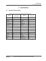
This product may be used in any of the following European Union nations.
ISO 3166
ISO 3166
Country
Country
2 letter code
2 letter code
Austria
AT
Latvia
LV
Belgium
BE
Liechtenstein
LI
Bulgaria
BG
Lithuania
LT
Cyprus
CY
Malta
MT
Czech Republic
CZ
Netherlands
NL
Denmark
DK
Norway
NO
Estonia
EE
Poland
PL
Finland
FI
Portugal
PT
France
FR
Romania
RO
Germany
DE
Slovakia
SK
Greece
GR
Slovenia
SI
Hungary
HU
Spain
ES
Iceland
IS
Sweden
SE
Ireland
IE
Switzerland
CH
Italy
IT
United Kingdom
BG
Revision 9
January 2012
OneWireless XYR 6000 Pressure Transmitter R120 User's Manual
3
2. Specifications
2.2. Certifications and approvals
2.2
Certifications and approvals
Transmitter
Refer to product label for applicable ratings.
Approval / Item
Ratings / Description
CSAcus Intrinsically
Safe
CL I, Div 1, Groups A, B, C, & D; CL II, Div 1, Groups E, F & G; CL III, T4
CSAcus Explosionproof
CL I, Div 1, Groups A, B, C, & D; CL II, Div 1, Groups E, F & G; CL III, T4
CL I, Zone 0: Ex ia IIC, T4; CL I, Zone 0: AEx ia IIC, T4
CL I, Zone 1: Ex d IIC, T4; CL I, Zone 1: AEx d IIC, T4
CSAcus Nonincendive
CL I, Div 2, Groups A, B, C & D; CL II, Div 2, Groups F & G; CL III, Div 2, T4
CL I, Zone 2: Ex nA IIC, T4; CL I, Zone 2: AEx nA IIC, T4
FM Approvals
CL I, Div 1, Groups A, B, C, & D; CL II, Div 1, Groups E, F & G; CL III, T4
Intrinsically Safe
CL I, Zone 0: AEx ia IIC, T4
FM Approvals
CL I, Div 1, Groups A, B, C, & D; CL II, Div 1, Groups E, F & G; CL III, T4
Explosionproof
CL I, Zone 1: AEx d IIC, T4
FM Approvals
CL I, Div 2, Groups A, B, C & D; CL II, Div 2, Groups F & G; CL III, Div 2, T4
Nonincendive
CL I, Zone 2: AEx nA IIC, T4
HON – ATEX
, Ex nA IIC, T4; Ta = 85°C, Zone 2
Non-Sparking
KEMA 08 ATEX0062X
Ex ia IIB; T4 Ta = 70ºC; Ex tD A20 IP66 T90ºC
Intrinsically Safe
Ex d [ia] IIB; T4 Ta = 70ºC; Ex tD A21 IP66 T90ºC
Flameproof
Non-Sparking
Ex nA [nL] IIC; T4 Ta = 84ºC; Ex tD A22 IP66 T90ºC
IECEx CSA 09.0001X
Intrinsically Safe
Flameproof
Ex ia IIB; T4 Ta = 70ºC; DIP A20 IP66 T90ºC
Ex d [ia] IIB; T4 Ta = 70ºC; DIP A21 IP66 T90ºC
Ex nA [nL] IIC; T4 Ta = 84ºC; DIP A22 IP66 T90ºC
Non-Sparking
Process Connections in
Division 2 / Zone 2
Division 2 / Zone 2 apparatus may only be connected to processes classified
as non-hazardous or Division 2 / Zone 2. Connection to hazardous (flammable
or ignition capable) Division 1 / Zone 0, or 1 process is not permitted.
Enclosure Type
Type 4X, IP 66
CRN
Canadian Registration Number
Class II and III installations and Type 4X/IP66 applications require that all cable and unused entries be
sealed with a NRTL (National Recognized Testing Laboratory) listed cable gland or conduit plug. Cable
glands and conduit plugs are not supplied with the product.
4
OneWireless XYR 6000 Pressure Transmitter R120 User's Manual
Revision 9
January 2012
2. Specifications
2.3. Agency compliance information
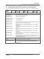
For detailed transmitter specifications see the following Specification and Model Selection Guides.
XYR 6000 Wireless Transmitter Differential Pressure (document 34-XY-03-22)
XYR 6000 Wireless Transmitter Absolute Pressure (document 34-XY-03-23)
XYR 6000 Wireless Transmitter Gauge Pressure (document 34-XY-03-24)
Provisioning Device
Install the Provisioning Device application on any PDA having
2.3
Windows Mobile version 4.2+
Infrared port.
Agency compliance information
This section contains the Federal Communications Commission (FCC), Industry Canada (IC) and Radio
Frequency compliance statements for the OneWireless XYR 6000 Wireless Transmitters device.
ATTENTION
XYR 6000 units must be professionally installed in accordance with the
requirements specified in the OneWireless XYR 6000 Agency Compliance
Professional Installation Guide.
FCC compliance statements
This device complies with Part 15 of FCC Rules and Regulations. Operation is subject to the
following two conditions: (1) This device may not cause harmful interference and (2) this device must
accept any interference received, including interference that may cause undesired operation.
This equipment has been tested and found to comply with the limits for a Class A digital device,
pursuant to Part 15 of the FCC Rules. These limits are designed to provide reasonable protection
against harmful interference in a residential installation. This equipment generates, uses, and can
radiate radiofrequency energy and, if not installed and used in accordance with these instructions, may
cause harmful interference to radio communications. Operation of this equipment in a residential area
is likely to cause harmful interference in which case the user will be required to correct the
interference at their own expense.
Intentional or unintentional changes or modifications must not be made to the XYR 6000 Wireless
Transmitters unless under the express consent of the party responsible for compliance. Any such
modifications could void the user’s authority to operate the equipment and will void the
manufacturer’s warranty.
IC compliance statements
To reduce potential radio interference to other users, the antenna type and its gain should be so chosen
that the equivalent isotropic radiated power (EIRP) is not more than that permitted for successful
communication.
Operation is subject to the following two conditions: (1) this device may not cause interference, and
(2) this device must accept any interference, including interference that may cause undesired operation
of the device.
This Class A digital apparatus complies with Canadian ICES-003.
French: Cet appareil numérique de la classe A est conforme à la norme NMB-003 du Canada. Revision 9
January 2012
OneWireless XYR 6000 Pressure Transmitter R120 User's Manual
5
2. Specifications
2.3. Agency compliance information
Radio Frequency (RF) statement
To comply with FCC’s and Industry Canada’s RF exposure requirements, the following antenna
installation and device operating configurations must be satisfied.
Remote Point-to-Multi-Point antenna(s) for this unit must be fixed and mounted on outdoor permanent
structures with a separation distance between the antenna(s) of greater than 20cm and a separation
distance of at least 20cm from all persons.
Remote Fixed Point–to-Point antenna(s) for this unit must be fixed and mounted on outdoor
permanent structures with a separation distance between the antenna(s) of greater than 20cm and a
separation distance of at least 100cm from all persons.
Furthermore, when using integral antenna(s) the XYR 6000 Wireless Transmitter unit must not be colocated with any other antenna or transmitter device and have a separation distance of at least 20cm
from all persons.
European Union restriction
The XYR 6000 Wireless Transmitters are in conformity with the applicable portions of the ETSI standards
as required by the R&TTE Directive 1999/5/EC.
France restricts outdoor use to 10mW (10dBm) EIRP in the frequency range of 2,454-2,483.5 MHz.
Installations in France must limit EIRP to 10dBm, for operating modes utilizing frequencies in the range of
2,454 – 2,483.5MHz.
Japanese Restrictions
For locations in Japan the transmitter power is restricted to 12.14dBm/Mhz {(32mW (15.4 dBm)]
maximum EIRP including the antenna.
6
OneWireless XYR 6000 Pressure Transmitter R120 User's Manual
Revision 9
January 2012
2. Specifications
2.4. Honeywell European (CE) Declaration of Conformity (DoC)
2.4
Honeywell European (CE) Declaration of Conformity (DoC)
This section contains the European Declaration of Conformity (DoC) statement, for the XYR 6000 OneWireless
products.
R&TTE
Directive
1999/5/EC
LVD
Directive
73/23/EEC
EMC
Directive
2004/108/EC
ATEX
Directive
94/9/EC
Harmonized Standards
EN 300 328 V1.7.1
Emissions Specification and Method:
EN 301 893 V1.4.1
Emissions Spec and Method
EN 301 489-17 V1.2.1
Immunity Specification:
EN 301 489-1 V1.6.1
Immunity Method:
IEC61326-1 : 2006
Electrical equipment for measurement, control and laboratory use – EMC
requirements – Part 1: General requirements
EN 60079-0 : 2006
Electrical apparatus for explosive gas atmospheres - Part 0: General
requirements
EN 60079-1 : 2004
Electrical apparatus for explosive gas atmospheres - Part 1: Flameproof
enclosure 'd'
EN 60079-11 : 2007
Electrical apparatus for explosive gas atmospheres - Part 11: Intrinsic
safety 'i'
EC 60079-15 : 2005
Electrical apparatus for explosive gas atmospheres - Part 15: Type of
protection 'n'
EN 61241-0 : 2007
Electrical apparatus for use in the presence of combustible dust - Part 0:
General Requirements
EN 61241-1 : 2004
Electrical apparatus for use in the presence of combustible dust - Part 1-1:
Electrical apparatus for use in the presence of combustible dust – Part 1:
Protection by enclosures "tD"
Manufacturer’s Name and
Address
Honeywell Process Solutions
525 East Market Street, York, PA 17403 USA
Compliance Statement
The product herewith complies with the harmonized standards listed
above. Typical product line systems and configurations have been tested,
for compliance.
Revision 9
January 2012
OneWireless XYR 6000 Pressure Transmitter R120 User's Manual
7
2. Specifications
2.4. Honeywell European (CE) Declaration of Conformity (DoC)
European Declaration of Conformity statements
8
Language
Statement
Česky
(Czech):
Honeywell tímto prohlašuje, že tento XYR 6000 Wireless
Transmitters je ve shodě se základními požadavky a dalšími
příslušnými ustanoveními směrnice 1999/5/ES.
Dansk
(Danish):
Undertegnede Honeywell erklærer herved, at følgende udstyr XYR
6000 Wireless Transmitters overholder de væsentlige krav og øvrige
relevante krav i direktiv 1999/5/EF.
Deutsch
(German):
Hiermit erklärt Honeywell, dass sich das Gerät XYR 6000 Wireless
Transmitters in Übereinstimmung mit den grundlegenden
Anforderungen und den übrigen einschlägigen Bestimmungen der
Richtlinie 1999/5/EG befindet.
Eesti
(Estonian):
Käesolevaga kinnitab Honeywell seadme XYR 6000 Wireless
Transmitters vastavust direktiivi 1999/5/EÜ põhinõuetele ja nimetatud
direktiivist tulenevatele teistele asjakohastele sätetele.
English
Hereby, Honeywell, declares that this XYR 6000 Wireless
Transmitters is in compliance with the essential requirements and
other relevant provisions of Directive 1999/5/EC.
Español
(Spanish):
Por medio de la presente Honeywell declara que el XYR 6000
Wireless Transmitters cumple con los requisitos esenciales y
cualesquiera otras disposiciones aplicables o exigibles de la Directiva
1999/5/CE.
Ελληνική
(Greek):
ΜΕ ΤΗΝ ΠΑΡΟΥΣΑ Honeywell ΔΗΛΩΝΕΙ ΟΤΙ XYR 6000 Wireless
Transmitters ΣΥΜΜΟΡΦΩΝΕΤΑΙ ΠΡΟΣ ΤΙΣ ΟΥΣΙΩΔΕΙΣ ΑΠΑΙΤΗΣΕΙΣ
ΚΑΙ ΤΙΣ ΛΟΙΠΕΣ ΣΧΕΤΙΚΕΣ ΔΙΑΤΑΞΕΙΣ ΤΗΣ ΟΔΗΓΙΑΣ 1999/5/ΕΚ.
Français
(French):
Par la présente Honeywell déclare que l'appareil XYR 6000 Wireless
Transmitters est conforme aux exigences essentielles et aux autres
dispositions pertinentes de la directive 1999/5/CE.
Italiano
(Italian):
Con la presente Honeywell dichiara che questo XYR 6000 Wireless
Transmitters è conforme ai requisiti essenziali ed alle altre disposizioni
pertinenti stabilite dalla direttiva 1999/5/CE.
Latviski
(Latvian):
Ar šo Honeywell deklarē, ka XYR 6000 Wireless Transmitters atbilst
Direktīvas 1999/5/EK būtiskajām prasībām un citiem ar to saistītajiem
noteikumiem.
Lietuvių
(Lithuanian):
Šiuo Honeywell deklaruoja, kad šis XYR 6000 Wireless Transmitters
atitinka esminius reikalavimus ir kitas 1999/5/EB Direktyvos nuostatas.
Nederlands
(Dutch):
Hierbij verklaart Honeywell dat het toestel XYR 6000 Wireless
Transmitters in overeenstemming is met de essentiële eisen en de
andere relevante bepalingen van richtlijn 1999/5/EG.
Malti
(Maltese):
Hawnhekk, Honeywell, jiddikjara li dan XYR 6000 Wireless
Transmitters jikkonforma mal-ħtiġijiet essenzjali u ma provvedimenti
oħrajn relevanti li hemm fid-Dirrettiva 1999/5/EC.
Magyar
(Hungarian):
Alulírott, Honeywell nyilatkozom, hogy a XYR 6000 Wireless
Transmitters megfelel a vonatkozó alapvetõ követelményeknek és az
1999/5/EC irányelv egyéb elõírásainak.
Polski
(Polish):
Niniejszym Honeywell oświadcza, że XYR 6000 Wireless
Transmitters jest zgodny z zasadniczymi wymogami oraz pozostałymi
stosownymi postanowieniami Dyrektywy 1999/5/EC.
OneWireless XYR 6000 Pressure Transmitter R120 User's Manual
Revision 9
January 2012
2. Specifications
2.5. IECEx Conditions of Certification
Language
Statement
Português
(Portuguese):
Honeywell declara que este XYR 6000 Wireless Transmitters está
conforme com os requisitos essenciais e outras disposições da
Directiva 1999/5/CE.
Slovensko
(Slovenian):
Honeywell izjavlja, da je ta XYR 6000 Wireless Transmitters v skladu
z bistvenimi zahtevami in ostalimi relevantnimi določili direktive
1999/5/ES.
Slovensky
(Slovak):
Honeywell týmto vyhlasuje, že XYR 6000 Wireless Transmitters
spĺňa základné požiadavky a všetky príslušné ustanovenia Smernice
1999/5/ES.
Suomi
(Finnish):
Honeywell vakuuttaa täten että XYR 6000 Wireless Transmitters
tyyppinen laite on direktiivin 1999/5/EY oleellisten vaatimusten ja sitä
koskevien direktiivin muiden ehtojen mukainen.
Svenska
(Swedish):
Härmed intygar Honeywell att denna XYR 6000 Wireless
Transmitters står I överensstämmelse med de väsentliga
egenskapskrav och övriga relevanta bestämmelser som framgår av
direktiv 1999/5/EG.
Íslenska
(Icelandic):
Hér með lýsir Honeywell yfir því að XYR 6000 Wireless Transmitters
er í samræmi við grunnkröfur og aðrar kröfur, sem gerðar eru í tilskipun
1999/5/EC.
Norsk
(Norwegian):
Honeywell erklærer herved at utstyret XYR 6000 Wireless
Transmitters er i samsvar med de grunnleggende krav og øvrige
relevante krav i direktiv 1999/5/EF.
For more information about the R&TTE Directive
The following website contains additional information about the Radio and Telecommunications Terminal
Equipment (R&TTE) directive:
http://ec.europa.eu/enterprise/rtte/faq.htm
2.5
IECEx Conditions of Certification
Parts of the antenna are non-conducting and the area of the non-conducting part exceeds the maximum
permissible areas for Category ll 1 G (Zone 0) according to IEC 60079-0. Therefore when the antenna is
used within a potentially explosive atmosphere, appropriate measures must be taken to prevent
electrostatic discharge.
Impact and friction hazards need to be considered according to IEC 600079-0 when the transmitter that is
exposed to the exterior atmosphere is made of light metal alloys, and used in Category ll 1 G (Zone).
ATEX Conditions for Safe Use
Because the enclosure of the enclosure of the XYR 6000 Wireless Transmitter is made from aluminum, if
it mounted in an area where the use of category 1G apparatus is required, it must be installed such that
even in the event of rare incidents, ignition sources due to impact and friction sparks are excluded.
Special precautions shall be taken to prevent the surface of the antenna of the XYR 6000 Wireless
Transmitter from being electrostatically charged
Revision 9
January 2012
OneWireless XYR 6000 Pressure Transmitter R120 User's Manual
9
3. Preparation
3.1. Installation
3. Preparation
3.1
Installation
Refer to the XYR 6000 Transmitter Quick Start Guide (document 34-XY-25-21) for installation, mounting
and wiring of your XYR 6000 transmitter.
3.2
Configuration
The XYR 6000 Transmitter contains the electronics interface compatible for connecting to the
OneWireless network. An operator uses the Wireless Builder application to configure blocks, to change
operating parameters, and to create linkages between blocks that make up the transmitter’s configuration.
These changes are written to the transmitter when it is authenticated by a security key.
3.3
Connecting to network
Use Authentication Device to connect your transmitter to the OneWireless network. See page 23.
3.4
Calibrating the transmitter
Overview
For all calibration methods, Wireless Builder must be used to unlock and take the channel out of service.
You can set the zero offset at the transmitter by use of the infrared port. Additional calibration commands
such as upper and lower trim are available in Wireless Builder.
Calibrate zero
Calibrates the sensor to correct the input measurement due to fill fluid and transmitter position effects once
the transmitter is installed and operating under process conditions.
ATTENTION
Setting user trim points will effectively override the calibration zero. Normally
the calibration zero is only required if you do not intend to provide processspecific trim points.
10
OneWireless XYR 6000 Pressure Transmitter R120 User's Manual
Revision 9
January 2012
3. Preparation
3.4. Calibrating the transmitter
Table 1 Calibrate zero
Step
1
Action
Apply zero input pressure for your transmitter’s pressure type as follows.
Differential: With process pressure applied, connect HP and LP inputs together using the
crossover valve on the 3-valve manifold or other equivalent method.
Gauge: Isolate the input pressure from the process and vent to the atmosphere.
Absolute: Due to the difficulty of applying absolute 0 psi, zero calibration of the AP transmitter is
not recommended.
2
In Wireless Builder, set the transmitter’s Write Lock to Unlocked.
3
In Wireless Builder, set the transmitter’s channel to OOS (Out of Service).
4
At the transmitter, verify the PV value is followed by an out of service (OUT SVC) message.
Use Authentication Device’s Device Local Configuration buttons to navigate to the transmitter’s
CAL menu.
If the transmitter is locked a LOCKED message will be displayed. Go to step 2.
If CAL menu is passcode protected, enter the passcode.
If the channel is not out of service a WRONG MODE message will be displayed. Go to step 3.
5
Select CAL ZERO. With CAL ZERO displayed, press Enter to set the current applied pressure
to zero. If successful the display will briefly show “ZERO SET”. If unsuccessful the display will
briefly show “ERROR”.
6
Exit the menu.
7
Reverse step 1.
8
When ready, in Wireless Builder return the transmitter’s channel to service and set Write Lock
to Locked.
Revision 9
January 2012
OneWireless XYR 6000 Pressure Transmitter R120 User's Manual
11
4. Function blocks
4.1. Introduction
4. Function blocks
4.1
Introduction
This section explains the construction and contents of the XYR 6000 Pressure Transmitter Function
Blocks.
4.2
Block description
Block types
Blocks are the key elements that make up the transmitter’s configuration. The blocks contain data (block
objects and parameters) which define the application, such as the inputs and outputs, signal processing and
connections to other applications. The XYR 6000 Transmitter contains the following block types.
Block Type
Function
Device
Contains parameters related to the overall field device rather than a
specific input or output channel within it. A field device has exactly one
device block.
AITB
Contains parameters related to a specific process input or output
channel in a measurement or actuation device. An AITB defines a
measurement sensor channel for an analog process variable
represented by a floating-point value. There is one AITB per sensor.
Radio
Contains parameters related to radio communication between the
transmitter and the multimode(s).
Block diagram
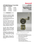
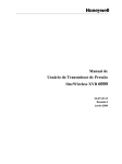
Figure 2 shows the blocks of the XYR 6000 Transmitter.
Transmitter
Sensor
Analog Input Transducer Block
(AITB)
Algorithm
Device Block
OUT
Read/
Write
Publish
Read/
Write
Communication Stack
Figure 2 Block Diagram
Each of these blocks contains parameters that are standard WNSIA-transmitter defined parameters. The
AITB and device blocks contain standard parameters common to all XYR 6000 transmitter models (that is,
pressure, temperature, DI, corrosion, HLAI) as well as pressure-specific parameters. The radio block
contains parameters for communication with the wireless network.
12
OneWireless XYR 6000 Pressure Transmitter R120 User's Manual
Revision 9
January 2012
4. Function blocks
4.3. Parameter details
4.3
Parameter details
The transmitter itself displays a few basic parameters, such as tag, serial number, device revision, build,
device address and WFN ID by accessing the quick view mode using the Authentication Device navigation
keys.
For more information on parameters, refer to the following documents.
OneWireless Wireless Builder User’s Guide
OneWireless Parameter Reference
Revision 9
January 2012
OneWireless XYR 6000 Pressure Transmitter R120 User's Manual
13
5. Operation
5.1. Overview
5. Operation
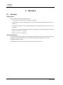
5.1
Overview
Display modes
The transmitter has the following display modes.
Test. Appears briefly after power-up to self-test the display.
Connection status. Appears when transmitter is not fully connected to the OneWireless network. See
section 5.2.
PV display. Default mode of the transmitter displays the PV and any status messages. See section 5.3
on page 16.
Quick view of transmitter identification parameters. Displays read-only parameters then returns to PV
display. See section 5.4 on page 20.
Menu. See section 5.5 on page 21.
Authentication Device
To navigate the transmitter displays and menus, hold the Authentication Device no more than 6” from the
transmitter and aim the infrared beam at the transmitter display while tapping the Device Local
Configuration buttons (Table 7).
Authentication Device menus are described in section 5.6 starting on page 22.
14
OneWireless XYR 6000 Pressure Transmitter R120 User's Manual
Revision 9
January 2012
5. Operation
5.2. Transmitter connection status
5.2
Transmitter connection status
Table 2 Transmitter connection status
Displayed
status
Definition
What to do
NO KEY
Transmitter needs a key from the
Authentication Device and is not transmitting.
Transmit a key to the transmitter. See page
23.
NOT CONN
Transmitter is in between discovery attempts.
If Transmitter does not make a connection
within five minutes, do the following:
Check that Key is correct for the network
you are trying to join.
Check that Multinode(s) in the local area
are turned on and are already a secure
part of the network.
Check if KeyServer is active.
Check the KeyServer Event Log to see if
the Transmitter is actively trying to join.
Errors in the Event Log show that the
Transmitter is trying to join but that there
are problems. Consult the OneWireless
Wireless Builder documentation for
troubleshooting errors.
DISCOVER
Transmitter has not made a connection to a
Multinode and is in discovery (searching for a
connection to a Multinode). Transmitter will
automatically enter a power saving mode if it
cannot make a connection and will retry later.
Wait for connection. If Transmitter does not
make a connection within five minutes, see
NOT CONN in this table.
SECURING
Transmitter has connected with the network
and is validating its key.
Wait for connection. If Transmitter does not
make a connection within five minutes, see
NOT CONN in this table.
CONNECTD
For units with radio firmware build* 53 or
higher:
For units with radio firmware build* 53 or
higher: No action required.
Transmitter has validated the key and has
made a secure connection with at least two
Multinodes. Transmitter should appear in
Wireless Builder as an uncommissioned
device.
For units with radio firmware build* 52:
Transmitter will periodically look for a
second Multinode in order to form a
redundant connection to the network. If
connected with only one Multinode Wireless
Builder will display a Secondary Multinode
Address of 0.
For units with radio firmware build* 52:
Transmitter has validated the key and has
made a secure connection with at least one
Multinode. Transmitter should appear in
Wireless Builder as an uncommissioned
device.
NO REDUN
Appears only on units with radio firmware
build* 53 or higher. No redundancy, that is,
Transmitter has connected with only one
Multinode.
No action required. The Transmitter will
periodically look for a second Multinode in
order to form a redundant connection to the
network
*Use the PDA to determine your radio firmware build number (page 21).
Revision 9
January 2012
OneWireless XYR 6000 Pressure Transmitter R120 User's Manual
15
5. Operation
5.3. Transmitter PV display
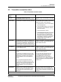
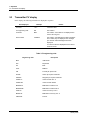
5.3
Transmitter PV display
In PV display, the following information is displayed in sequence.
Item displayed
Example
Details
PV value
+14.7
Latest PV value.
PV engineering units
PSI
See Table 3.
PV status
BAD
See Table 4. If PV status is not displayed then
the PV value is good.
Device status
LOW BAT
See Table 5. If multiple device status messages
are in effect, they are displayed one message
per channel until all messages have been
displayed.
If no device status is displayed then the device
status is normal.
Table 3 PV engineering units
Engineering units
16
Description
MPa
milliPascals
kPa
kilopascals
bar
Bars
mbar
Millibars
PSI
Pounds per square inch
G/CM2
Grams per square centimeter
KG/CM2
Kilograms per square centimeter
INH2O 4C
Inches of water at 4° C
INH2O 68F
Inches of water at 68°F
MMH2O 4C
Millimeters of water at 4°C
MMH2O 68F
Millimeters of water at 68° F
INHG 0C
Inches of mercury at 0° C
MMHG 0C
Millimeters of mercury at 0° C
PERCENT
Percent
OneWireless XYR 6000 Pressure Transmitter R120 User's Manual
Revision 9
January 2012
5. Operation
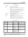
5.3. Transmitter PV display
Table 4 PV status
PV status
Cause - Action
(blank)
PV is normal – no action required
BAD
Possible calibration error – Clear calibration
AITB can not execute due to internal firmware state – Attempt cold restart of
device.
AITB can not execute due to hardware fault – Replace sensor board
Sensor failure – Check Connection between Sensor board and Meter Body.
Meter Body Characterization Data is Bad – Replace Meter Body
Meter Body A/D Failure – Replace Meter Body
Meter Body Sensor Fail – Replace Meter Body
BAD CONFIG
BAD E FAIL
UNC
Configuration is bad – Check possible units and range settings for input type
and correct AITB configuration.
Hardware fault detected - Replace sensor board
Warning: Calibration (zero or trim) is causing excessive adjustment to
characterization value.
Warning: Input inaccurate due to uncertain input data integrity.
Warning: Input inaccurate due to input conversion limitations or resolution.
Warning: Input outside of characterized range. Value is estimated.
Table 5 Device status
Transmitter
display
Wireless Builder display
Definition
What to do
OUT SVC
OOS
All channels are out of
service.
Restore mode to Auto in Wireless
Builder.
SENS ERR
Sensor Error
Sensor can not access
meter body A/D
converter.
Check connection between sensor
module and meter body. If still
doesn't work, replace sensor. See
page 32.
CHAR ERR
Characterization Error
Sensor can not access
meter body
characterization or the
characterization is
invalid.
Check connection between sensor
module and meter body. If still
doesn't work, replace sensor. See
page 32.
OVR TEMP
Over Temperature
The meter body has
exceeded the maximum
temperature as defined
by the meter body
characterization data.
Determine cause excessive
temperature.
Revision 9
January 2012
OneWireless XYR 6000 Pressure Transmitter R120 User's Manual
17
5. Operation
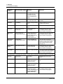
5.3. Transmitter PV display
Transmitter
display
Wireless Builder display
Definition
What to do
OVR LOAD
Over Load
The applied pressure has
exceeded the limit
defined by the meter
body characterization
data.
Determine cause of over pressure.
CAL ERR
Calibration Error
Calibration Data Invalid
or could not be read.
Use Cal Clear, Restore, or User
Calibrate.
LOW BAT
Low Battery
Battery Voltage Critically
Low
Replace batteries as soon as
possible. See page 34.
LOW PWR
Low Power
External Power Critically
Low
Check external 24V power supply
NO RADIO
Radio Interprocessor
Comm Error
Radio Board is not
accessible.
Restart both the radio and sensor.
If condition persists, replace
sensor module. See page 32.
BAD RADIO
SPI
Sensor Radio SPI
Communication Failure
Radio detected loss of
communication with
sensor board over the
inter-processor
communication link.
Restart both the radio and sensor.
If condition persists, replace
sensor module. See page 32.
BAD RADIO
EEPROM
EEPROM SPI
Communication Failure
Radio EEPROM SPI
Communication failure
The radio will not be able to
perform firmware upgrades but will
operate normally using installed
code. Replace sensor module.
See page 32.
RADIO WDT
RESET
WDT Reset Occurred
Radio Watch Dog
Timeout detected
Restart both the radio and sensor.
If condition persists, replace
sensor module. See page 32.
BAD RADIO
Radio Circuitry Failure
Radio circuitry has failed
The radio processor detected error
on internal radio circuitry. Replace
sensor module. See page 32.
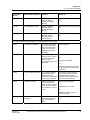
The following status messages have multiple meanings. Refer to Wireless Builder Device Status for exact cause.
18
INP FAIL
Input Failure
Input Error
Possible meter body sensor
failure.
INP FAIL
A/D Failure
Diagnostics detected
defect with Analog to
Digital Converter.
Replace sensor module. See page
32.
E FAIL
A/D Failure
Diagnostics detected
defect with Analog to
Digital Converter.
Replace sensor module. See page
32.
E FAIL
Electronics Failure
Electronic Failure
detected on Sensor
Board. Could be caused
by one of the status
items marked by *.
Restart both the radio and sensor.
If condition persists, replace
sensor module. See page 32.
OneWireless XYR 6000 Pressure Transmitter R120 User's Manual
Revision 9
January 2012
5. Operation
5.3. Transmitter PV display
Transmitter
display
Wireless Builder display
Definition
What to do
E FAIL*
NVM Fault*
Startup diagnostics
detected defect in
Sensor Non-Volatile
Memory
Replace sensor module. See page
32.
E FAIL*
Program Memory Fault*
Startup diagnostics
detected defect in
Sensor Read Only
Memory
Replace sensor module. See page
32.
E FAIL*
RAM Fault*
Startup diagnostics
detected defect in
Processor Random
Access Memory
Replace sensor module. See page
32.
The following statuses are displayed only in Wireless Builder Device Status.
blank
Excess Zero Calibration
The selected zero offset
or the lower calibration
trim point is beyond 5%
of the lower end of the
characterized range of
the device.
Clear Calibration
blank
Excess Span Calibration
The calibrated upper and
lower trim has produced
a span that is greater
than 5% of the
characterized span of the
transmitter.
Clear Calibration
Or
Set Factory Calibration
Or
Check the applied trim points and
re-attempt lower and upper (trim)
calibration.
blank
Excess Calibrated Range
The selected calibration
points used for upper
and lower trim are
outside the characterized
range of the transmitter.
Check that the upper and lower
trim points are both within the
characterized range of the
transmitter and re-attempt upper
and lower (trim) calibration.
blank
Calibration Cleared
Indicates that both the
upper and lower trim
points as well as the zero
offset has been cleared.
The calibration source is
none.
Select Factory Calibration
Or
Calibration the zero offset
Or
Calibrate using the lower and
upper trim points.
blank*
Revision 9
January 2012
Device/Firmware
Mismatch*
Sensor Board Firmware
Error. The software did
not pass verification
tests.
Replace sensor module. See page
32.
OneWireless XYR 6000 Pressure Transmitter R120 User's Manual
19
5. Operation
5.4. Transmitter quick view of parameters
Transmitter
display
Wireless Builder display
Definition
What to do
blank*
Heap Memory Not
Available*
Heap Allocation Failure.
Software detected heap
shortage and some
communication packets
may have been dropped.
Clear by warm restart of device. If
condition persists contact
Honeywell service.
blank*
Watchdog Timer Error*
Sensor Watchdog
Timeout. The processor
was restarted due to
unexpected operation.
Clear by warm restart of device. If
condition persists contact
Honeywell service.
5.4
Transmitter quick view of parameters
If the Up or Down key is pressed using the Authentication Device while in PV display mode, the display
will enter parameter quick view mode. Successive presses of the Up key will increment to the next
parameter in the following table, or exit to PV mode if at the last parameter. The Down key will
decrement to the previous parameter or exit if at the first parameter. The Enter key will exit to PV display
mode at any time.
Position
20
Parameter
Description
1
Vendor Name
HONEYWELL
2
HONEYWELL
XYR 6000 MULTI AI DI DO
3
Tag Name
HON_XYR6000_MAIDIDO_1234567890
4
SDREV
Sensor device revision
5
SBLD
Sensor build number
6
Radio Type
DSSS
7
RBLD
Radio build number
8
WFN
Wireless field network identifier
9
NET
Network device address
10
MODE/CHANNEL
Frequency hopping mode & channel
OneWireless XYR 6000 Pressure Transmitter R120 User's Manual
Revision 9
January 2012
5. Operation
5.5. Transmitter menu
5.5
Transmitter menu
Menu tree
At the PV display, press Enter to access the menus. To interact with the menus use the Device Local
Configuration onscreen buttons (page 25) or the buttons on your PDA.
Table 6 Menu tree
Menu item
Description
CAL
Calibration menu. May be password-protected. See Table 7 on page 25 for
password number entry.
CAL ZERO
RADIO
Radio menu
PRI RSSI
Revision 9
January 2012
Calibrate zero. See page 10.
Primary receive signal strength. Read only. Signal strength 00 is too weak to
connect to the network.
Displayed Value
Value dBm
Rx Margin dB
00
< -86
< 10
01
-86 to -81
10 to 15
02
-80 to -75
16 to 21
03
-74 to -69
22 to 27
04
-68 to -63
28 to 33
05
-62 to -57
34 to 39
06
-56 to -51
40 to 45
07
-50 to -45
46 to 51
08
-44 to -11
52 to 85
09
≥ -10
Saturation
SEC RSSI
Secondary receive signal strength. Same as PRI RSSI. Read only.
WFN ID
Wireless Field Network ID. Read only.
DEV ADD
Device address. Read only.
TX POWER
Radio transmit power. Read only.
OneWireless XYR 6000 Pressure Transmitter R120 User's Manual
21
5. Operation
5.6. Authentication device menus
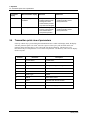
5.6
Authentication device menus
Overview
Hold the Authentication Device no more than 6” from the transmitter and aim the infrared beam at the
transmitter display while tapping on the screen command or button.
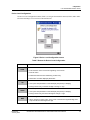
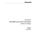
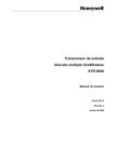
Main menu
The main menu is shown below. Details start on the next page.
Figure 3 Main menu
22
OneWireless XYR 6000 Pressure Transmitter R120 User's Manual
Revision 9
January 2012
5. Operation
5.6. Authentication device menus
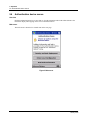
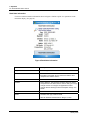
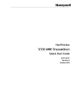
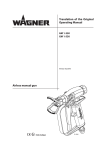
Security and Node Deployment
Use this to:
receive new security keys,
transmit security keys for connecting the transmitter (or other nodes) to the OneWireless network,
clear all security keys from the PDA,
clear the transmitter’s key and reset its configuration to factory default (such as for decommissioning).
Figure 4 Security and Node Deployment
Revision 9
January 2012
OneWireless XYR 6000 Pressure Transmitter R120 User's Manual
23
5. Operation
5.6. Authentication device menus
To connect your transmitter to the OneWireless network perform the following steps.
Step
1
Action
If the PDA contains no keys, obtain new security keys from the PC
application Key Server Manager.
To do this, select Receive Security Keys. Keys can be received either
through Infrared (by aiming PDA at the infrared dongle) or through an
ActiveSync/USB connection. See Key Server Communication Method
under Advanced options on page 28 for details.
Important: The Comm Method settings must match in the PC’s Key Server
Manager and in the Authentication Device (both must be set to Infrared or
both to ActiveSync) in order for your PDA to receive security keys. See Key
Server Communication Method under Advanced options on page 28 for
details.
2
When the Authentication Device has valid unexpired keys, aim it at the
transmitter and transmit a key to the transmitter. The transmitter will validate
the key and then use it to make a connection to the OneWireless Network.
The Transmitter may continue to show the diagnostic message “NO KEY” for
a brief time while it validates the key before showing the “DISCOVER”
message.
To verify your transmitter has been authenticated, see the Connection prompt
on the Read Node Info screen (page 26).
To decommission your transmitter from the OneWireless network, select Clear Key and Restart Node.
This clears the transmitter’s key, network and security configurations, and resets the transmitter to its
factory default settings. perform the following steps.
Select Clear Keys from Handheld (under Advanced Options) when:
The PDA has keys from one system, but you have moved your Authentication Device to another
system, or
you want to clear all keys so that you cannot deploy any more keys without going to the key server
manager and getting more.
For more details on keys, refer to Getting Started with Honeywell OneWireless Solutions.
24
OneWireless XYR 6000 Pressure Transmitter R120 User's Manual
Revision 9
January 2012
5. Operation
5.6. Authentication device menus
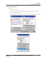
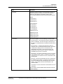
Device Local Configuration
Use Device Local Configuration buttons (Table 7) to navigate the transmitter menus (Table 6) and to make
selections and changes. You can also use the PDA buttons.
Figure 5 Device Local Configuration screen
Table 7 Buttons for Device Local Configuration
Button
Function
Enter the Menu Tree.
Enter submenu of the menu that is appearing on the screen.
Execute action.
Submit the entered number while doing number entry.
Read value of certain displayed parameters.
Go to the next menu in the same level.
View quick view parameters in Normal Display Sequence (PV Display).
During number entry, increment the digit or change +/- sign.
Go to the previous menu in the same level.
View quick view parameters in Normal Display Sequence (PV Display).
During number entry, decrement the digit or change +/- sign.
Go to the upper menu level.
When changing a number value, move cursor to the left/more significant digit, then
wrap around to the least significant digit.
Revision 9
January 2012
OneWireless XYR 6000 Pressure Transmitter R120 User's Manual
25
5. Operation
5.6. Authentication device menus
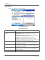
Read Node Information
Use this to read the transmitter information shown in Figure 6. Similar to quick view parameters on the
transmitter display. (See page 20.)
Figure 6 Read Node Information
Item
Description
Tag
The name given to this transmitter
Serial
Transmitter serial number. This is the WBSN on the
transmitter’s nameplate. Do not confuse this with the other
nameplate item marked “Serial.”
NwAddr
Network Address of the device in hexadecimal.
DevRev
Device Revision. This parameter changes whenever objects
and parameters are added, deleted, or their data type or range
changes. It does not change if the application firmware
changes without affecting the device description. Range: 0 to
65535.
Build
Sensor firmware and radio firmware build numbers.
Radio
Hardware radio type, FHSS or DSSS
WFN ID: Wireless Field Network ID. Range: 0 to 255.
26
OneWireless XYR 6000 Pressure Transmitter R120 User's Manual
Revision 9
January 2012
5. Operation
5.6. Authentication device menus
Item
FH Mode
Description
Frequency group or frequency channel selection used by the
wireless network of the device. The value must match the
value set in the gateway and interface nodes to allow
communication between the device and the wireless network.
Modes:
US Channel #1
US Channel #6
US Channel #11
US Guard Bands
EU Channel #1
EU Channel #7
EU Channel #13
EU Guard Bands
US/EU Spec Div A
US/EU Spec Div B
US/EU Channel #3
US/EU Channel #10
Complete Spectrum
Connection
The first line displays one of the following connection states.
No Security Key – No security key has been deployed to the
device or multinode. The user must give a security key to
the device or multinode before it will join the wireless sensor
network.
No Connection – A security key exists in the device or
multinode, but no connection has been formed. The device
or multinode is waiting to form a connection and will
automatically retry shortly. Users may transmit a new
security key in order to force the device or multinode to
immediately retry to form a connection.
Discovering – The device is attempting to form a connection
to the wireless sensor network. The device is discovering
multinodes and, if a multinode is found, will transition to the
securing state.
Securing – The device is attempting to form a connection to
the wireless sensor network. The device has discovered
one or two multinodes and is attempting to form a secure
session. If successful, the device will transition to the
connected state.
Connected – A secure connection is formed with one or two
multinodes.
The second line contains detailed state information useful for
problem reporting.
Revision 9
January 2012
OneWireless XYR 6000 Pressure Transmitter R120 User's Manual
27
5. Operation
5.6. Authentication device menus
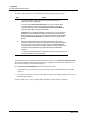
Advanced Options
Advanced options are non-typical configuration commands.
Figure 7 Advanced Options
Table 8 Advanced Options
Item
Description
Key Server Communication
Method
Determines how the PDA will receive security keys from the PC’s Key Server
Manager application. From the Comm Method menu select one of the
following methods.
ActiveSync – Select this to receive keys over a USB connection, such as
while the PDA battery is being charged in its base.
Infrared – Select this to receive keys over the infrared port.
Important: The Comm Method settings match in the PC’s Key Server
Manager and in the Authentication Device (both must be set to Infrared or both
to ActiveSync) in order for your PDA to receive security keys.
Read Tracelog Flag
Not available for transmitters. Used with multinodes. Reads conditional
tracelog flag value. Tracelog flags are used to enable and disable logging
functionality used for field support.
Write Tracelog Flag
Not available for transmitters. Used with multinodes. Writes conditional
tracelog flag value. Tracelog flags are used to enable and disable logging
functionality used for field support .
Select Infrared Communication
Port
Overrides the detected infrared communication port detected on your PDA. If
infrared communication is not functioning, you can override the detected
settings using this option.
Read TX Power Level
Reads the transmission power level of the transmitter radio.
28
OneWireless XYR 6000 Pressure Transmitter R120 User's Manual
Revision 9
January 2012
6. Maintenance/Repair
6.1. Introduction
6. Maintenance/Repair
6.1
Introduction
This section provides information about preventive maintenance routines and replacing damaged parts.
The topics covered in this section are:
Preventive maintenance of the meter body barrier diaphragms and process piping to the transmitter.
Replacement of damaged parts such as the transmitter display/sensor and batteries.
6.2
Preventive maintenance
The XYR 6000 transmitter itself does not require any specific maintenance routine at regularly scheduled
intervals. However, you should consider carrying out these typical inspection and maintenance routines on
a schedule that is dictated by the characteristics of the process medium being measured and whether blowdown facilities or purge systems are being used.
Check piping for leaks.
Clear the piping of sediment or other foreign matter.
Clean the transmitter’s pressure chambers including the barrier diaphragms.
6.3
Inspecting and cleaning barrier diaphragms
Depending on the characteristics of the process medium being measured, sediment or other foreign
particles may collect in the process head cavity/chamber and cause faulty measurement. In addition, the
barrier diaphragm or diaphragms in the transmitter’s meter body may become coated with a residue from
the process medium. The latter is also true for external diaphragms on flange mount and remote seal type
transmitters.
In most cases, you can readily remove the process head or heads from the transmitter’s meter body to clean
the process head cavity and inspect the barrier diaphragm or diaphragms. For flange mount and remote seal
diaphragms, you may only need to run a purge line in the tank to rinse off the face of the diaphragm.
The procedure in Table 9 outlines the general steps for inspecting and cleaning barrier diaphragms. You
may have to modify the steps to meet your particular process or transmitter model requirements. Figure 8
shows an exploded view of a DP transmitter’s meter body for reference.
WARNING
Risk of death or serious injury by explosion. Do not open transmitter
enclosure when an explosive gas atmosphere is present.
Tools required
5/8” Wrench or Socket for 7/16” Dia. Hex Bolt
3/4” Wrench or Socket for 7/16” Hex Nut
Calibrated torque wrench. For the most accurate performance, select a torque wrench with which the
applied torque value is near the middle of the tool’s torque range. For example, if applying 68 N-M
(50 Lb-Ft), select a torque wrench with range of 7 N-M to 136 N-M (5 to 100 Lb-Ft).
Revision 9
January 2012
OneWireless XYR 6000 Pressure Transmitter R120 User's Manual
29
6. Maintenance/Repair
6.3. Inspecting and cleaning barrier diaphragms
Procedure
Table 9 Inspecting and Cleaning Barrier Diaphragms
Step
Action
1
Close all valves and isolate transmitter from process. Open vent in process head to drain fluid
from transmitter’s meter body, if required.
ATTENTION
We recommend that you remove the transmitter from service and move it to a clean area
before taking it apart.
WARNING
Risk of death or serious injury by explosion. Do not open transmitter enclosure when an
explosive gas atmosphere is present.
2
Remove nuts from bolts that hold process head or heads to meter body. Remove process
heads and bolts. See Figure 8.
3
Remove gasket and clean interior of process head using soft bristle brush and suitable solvent.
CAUTION
Diaphragm surface is fragile. Be very gentle, do not damage.
4
Inspect barrier diaphragm for any signs of deterioration or corrosion. Look for possible residue
and clean if necessary.
If diaphragm is dented, has distorted convolutions or radial wrinkles, performance may be
affected. Contact Honeywell for assistance.
5
Replace process head gasket.
ATTENTION
We recommend that you install a new gasket whenever a process head is removed for
cleaning.
For process heads of a GP or AP transmitter with dual-head design, see illustration for
differential pressure transmitters in Figure 8.
30
6
Coat threads on process head bolts with anti-seize compound such as “Neverseize” or
equivalent.
7
Replace process head or heads and bolts. Finger tighten nuts.
8
Use a torque wrench to gradually tighten nuts to torque rating shown in Table 10, in sequence
shown in Figure 8. Tighten head bolts in stages of 1/3 full torque, 2/3 full torque, and then full
torque.
9
Return transmitter to service.
OneWireless XYR 6000 Pressure Transmitter R120 User's Manual
Revision 9
January 2012
6. Maintenance/Repair
6.3. Inspecting and cleaning barrier diaphragms
Tighten in
sequence shown
1
3
2
4
Figure 8 Assembly of DP Transmitter Process Heads
Torque ratings
Table 10 lists process head bolt torque ratings for given transmitter type.
Table 10 Process Head Bolt Torque Ratings
Bolt Type 7/16 x 14 UNC
Meterbody Type
50019775XXXX
Revision 9
January 2012
51452557-001
(Carbon Steel - standard;
no option specified)
51452557-002 and –003
(NACE [“CR” option], NonNACE [“SS” option] 316
Stainless Steel)
51452557-004
(B7M Alloy Steel
[“B7” option])
67,8 N•M +/- 3,4 N•M
(50.0 Lb-Ft +/- 2.5 Lb-Ft)
56,9 N•M +/- 2,8 N•M
(42.0 Lb-Ft +/- 2.1 Lb-Ft)
48,8 N•M +/- 2,4 N•M
(36.0 Lb-Ft +/- 1.8 Lb-Ft)
OneWireless XYR 6000 Pressure Transmitter R120 User's Manual
31
6. Maintenance/Repair
6.4. Replacing sensor module
6.4
Replacing sensor module
Tools required
#1 Phillips Screwdriver or 1/8” Slotted Screwdriver
Torque Screwdriver
1.5 mm hex key
Procedure
WARNING
Risk of death or serious injury by explosion. Do not open transmitter
enclosure when an explosive gas atmosphere is present.
CAUTION
Take precautions against electrostatic discharge to prevent damaging the
sensor module.
Table 11 Sensor module replacement
Step
Action
1
Honeywell recommends that the transmitter be removed from service and moved to a clean
area before servicing.
2
Loosen the M3 locking set screw on the display end-cap. See item 1 in Figure 9. Unscrew and
remove the end cap.
3
Loosen the two screws on the sensor module. See items 2 in Figure 9.
4
Disconnect each connector on the sensor module. See items 3 in Figure 9.
5
Install new sensor module. Be sure to orient sensor module in the proper viewing orientation
before tightening two sensor compartment screws.
Reverse steps 1-4.
Torque screws to 0,4 – 0,6 N-M (3.5 – 5.3 Lb-in).
Honeywell recommends lubricating the end cap O-ring with a Silicone Grease such as Dow
Corning #55 or equivalent before replacing the end cap.
Return transmitter to service.
32
OneWireless XYR 6000 Pressure Transmitter R120 User's Manual
Revision 9
January 2012
6. Maintenance/Repair
6.4. Replacing sensor module
3
2
1
3
2
Figure 9 Sensor module removal and replacement
Revision 9
January 2012
OneWireless XYR 6000 Pressure Transmitter R120 User's Manual
33
6. Maintenance/Repair
6.5. Replacing batteries
6.5
Replacing batteries
When to replace
When the transmitter displays a LOW BAT message you have 2-4 weeks to replace both batteries before
they expire. When batteries are removed or expired, all transmitter data is retained in the transmitter’s nonvolatile memory.
Tools required
#1 Phillips Screwdriver or 1/8” Slotted Screwdriver
Torque Screwdriver
1.5 mm hex key
Procedure
ATTENTION
Batteries must be replaced only by a trained service technician.
WARNINGS
Risk of death or serious injury by explosion. Do not open transmitter
enclosure when an explosive gas atmosphere is present.
Batteries must not be changed in an explosive gas atmosphere.
If IS Battery Pack, Honeywell 50047517-001, has been installed in the
Wireless Transmitter, the transmitter enclosure maybe opened when an
explosive gas atmosphere is present. Otherwise, do not open transmitter
enclosure when and explosive gas atmosphere is present.
- When not in use the Battery Pack must be stored in a non Hazardous
Area
The batteries used in this device may present a risk of fire or chemical
burn if mistreated. Do not recharge, disassemble, heat above 100°C
(212°F), or incinerate.
When installing batteries, do not snag the battery terminal on the clip or
the battery may be damaged. Do not apply excessive force.
Do not drop. Dropping the battery may cause damage. If a battery is
dropped, do not install the dropped battery into the transmitter. Dispose
of dropped battery promptly per local regulations or per the battery
manufacturer’s recommendations.
SHOCK HAZARD
Depending on your installation, transmitter input wiring sources may contain
high voltage. Disconnect all power from transmitter input sources before
accessing the batteries. Failure to do so could result in death or serious injury
if the input terminals or wires are accidentally touched.
34
OneWireless XYR 6000 Pressure Transmitter R120 User's Manual
Revision 9
January 2012
6. Maintenance/Repair
6.5. Replacing batteries
IS Battery Pack, 50047517-501
Table 12: IS Battery Pack replacement procedure
Step
1
Action
WARNING
DO NOT DISASSEMBLE OR ASSEMBLE WHEN AN EXPLOSIVE ATMOSPHERE IS PRESENT
Figure 10: IS Battery Pack
2
Loosen the M3 locking set screw on the battery end-cap (opposite end from display). See item 1 in
Figure 1. Unscrew and remove the end cap.
3
Using thumb and forefinger, squeeze the battery connector at top and bottom to disengage the
locking mechanism, then pull to disconnect. See item 2 in Figure 1.
4
Loosen the two battery holder retaining screws (closest to the batteries). See item 3 in Figure 1.
The screws are captive.
5
Pull the battery holder out of the transmitter.
6
Remove top of battery pack by using a #1 Philips or 1/8” slotted screwdriver for the screws identified
as #3 in Figure 10.
7
Remove the old batteries and dispose of them promptly according to local regulations of the battery
manufacturer’s recommendations.
8
Install the batteries following the polarity as noted on the lid
9
Re-install top of the battery pack and tighten screws
10
Insert the Battery pack into the transmitter. Reattach the screws as indicated in Figure 10, item 3, to
0.4 to 0.6 N-M (3.5 – 5.3 Lb-in).
Reconnect the Battery Pack connector
Honeywell recommends lubricating the end cap with a silicone grease such as Dow Corning #55 or
equivalent before replacing the end cap
11
Screw the cap back on and tighten the M3 locking screw
Revision 9
January 2012
OneWireless XYR 6000 Pressure Transmitter R120 User's Manual
35
6. Maintenance/Repair
6.6. Replacing 24V external power module
6.6
Replacing 24V external power module
When to replace
When the transmitter displays LOW PWR and external power is present and sufficient. When the external
power is removed to allow replacement of the module, all transmitter data is retained in the transmitter’s
nonvolatile memory.
Tools required
• #1
• Torque
• 1.5
Phillips Screwdriver or 1/8” Slotted Screwdriver
Screwdriver
mm hex key
Procedure
ATTENTION
24V power module must be replaced only by a trained service technician.
WARNINGS
Risk of death or serious injury by explosion. Do not open transmitter
enclosure when an explosive gas atmosphere is present.
SHOCK HAZARD
36
Depending on your installation, transmitter input wiring sources may
contain high voltage. Disconnect all power from transmitter input sources
before accessing the 24V power module. Failure to do so could result in
death or serious injury if the input terminals or wires are accidentally
touched.
OneWireless XYR 6000 Pressure Transmitter R120 User's Manual
Revision 9
January 2012
6. Maintenance/Repair
6.6. Replacing 24V external power module
Figure 11 24V Power Supply Module Assembly
24V Wiring Connector
M3 Locking
Screw
Power Connector
Power Module
Mounting Screws
Revision 9
January 2012
OneWireless XYR 6000 Pressure Transmitter R120 User's Manual
37
6. Maintenance/Repair
6.6. Replacing 24V external power module
Table 13 24V External power module
J2
Step
Action
1
Loosen the M3 locking set screw on the end-cap (opposite end from display). See Figure 10.
Unscrew and remove the end cap.
2
Using thumb and forefinger squeeze the power connector at top and bottom to disengage the
locking mechanism then pull to disconnect. See Figure 10.
3
Unplug the 24V wiring from the module
4
Loosen the two 24V power module retaining screws. The screws are captive.
5
Pull the 24V power module out of the transmitter.
6
The replacement 24V Power Modules are supplied with the “J2” Jumper in the NON-RTD
position. For 24V Transmitters utilizing RTD sensors, move the “J2” jumper to the “RTD”
position on the power module shown above in Table 13.
7
Insert the replacement 24V power module into the transmitter. Reattach the screws and tighten
to 0,4 – 0,6 N-M (3.5 – 5.3 Lb-in).
Re-connect battery connector.
Honeywell recommends lubricating the end cap O-ring with a Silicone Grease such as Dow
Corning #55 or equivalent before replacing the end cap.
38
8
Screw the end cap back on and tighten the M3 locking screw.
9
Dispose of the Power Module according to local regulations
OneWireless XYR 6000 Pressure Transmitter R120 User's Manual
Revision 9
January 2012
6. Maintenance/Repair
6.7. Replacing antenna
6.7
Replacing antenna
Tools required
#1 Phillips Screwdriver or 1/8” Slotted Screwdriver
Torque Screwdriver
1.5 mm hex key
Procedure
ATTENTION
You must replace your antenna with the same type, that is, elbow, straight, or
remote. Changing to a different antenna type is not permitted by approval
agencies.
CAUTION
Take precautions against electrostatic discharge to prevent damaging the
sensor module.
WARNING
POTENTIAL ELECTROSTATIC CHARGING HAZARD
The integrally mounted antenna shroud is made of Teflon® and has a surface
resistance greater than 1G ohm per square. When the XYR 6000 transmitter
is installed in potentially hazardous locations care should be taken not to
electrostatically charge the surface of the antenna shroud by rubbing the
surface with a cloth, or cleaning the surface with a solvent. If electrostatically
charged, discharge of the antenna shroud to a person or a tool could possibly
ignite a surrounding hazardous atmosphere.
Revision 9
January 2012
OneWireless XYR 6000 Pressure Transmitter R120 User's Manual
39
6. Maintenance/Repair
6.7. Replacing antenna
Table 14 Antenna replacement procedure
Step
40
Action
1
Honeywell recommends that the transmitter be removed from service and moved to a clean
area before servicing.
2
Loosen the M3 locking set screw on the display end-cap. See item 1 in Figure 12. Unscrew
and remove the front end cap.
3
Loosen the two screws on the sensor module. See items 2 in Figure 12.
4
Remove the sensor module from the transmitter body and disconnect the antenna connector
from CN2 connector on the sensor module. See item 3 in Figure 12.
5
Loosen the locking set screw at the antenna base. Unscrew the antenna from the transmitter.
Remove the antenna and its connector from the transmitter. See Figure 12.
6
Feed the new antenna’s connector through the antenna hole to the front of the transmitter. Do
not connect to sensor module yet. Lubricate O-ring with a Silicone Grease such as Dow
Corning #55 Screw new antenna into transmitter body until finger-tight, then back off 180
degrees to permit adjustment later.
7
Attach antenna connector to CN2 connector on sensor module. See item 3 in Figure 12.
8
Insert sensor module. Orient in the proper viewing orientation before tightening two sensor
compartment screws. See items 2 in Figure 12. Torque screws to 0,4 – 0,6 N-M (3.5 – 5.3 Lbin).
9
Replace the front end cap. Honeywell recommends lubricating the front end cap O-ring with a
Silicone Grease such as Dow Corning #55 or equivalent before replacing the end cap.
10
Adjust antenna for best reception. Don’t rotate antenna more than 180 degrees either direction
or you could twist and break the antenna wiring inside. Tighten the antenna locking set screw.
OneWireless XYR 6000 Pressure Transmitter R120 User's Manual
Revision 9
January 2012
6. Maintenance/Repair
6.7. Replacing antenna
Antenna connector
3
2
1
2
Figure 12 Antenna replacement
Revision 9
January 2012
OneWireless XYR 6000 Pressure Transmitter R120 User's Manual
41
6. Maintenance/Repair
6.8. Parts
6.8
Parts
Transmitter body
The following replacement parts may be ordered from Honeywell.
Part number
42
Qty.
Description
50015866-502
1
ELECTRONICS MODULE ASSEMBLY aka SENSOR MODULE for Pressure
50015866-506
1
ELECTRONICS MODULE ASSEMBLY aka SENSOR MODULE for PressureIntrinsically Safe
50015866-510
1
ELECTRONICS MODULE ASSEMBLY aka SENSOR MODULE for Pressure-DSSS
Intrinsically Safe
50015623-501
1
CAP ASSEMBLY, BATTERY, ALUMINUM, DARK BEIGE
50016190-501
1
CAP ASSEMBLY, LCD, ALUMINUM, DARK BEIGE
50026009-501
1
CAP ASSEMBLY, BATTERY, STAINLESS STEEL
50026127-501
1
CAP ASSEMBLY, LCD, STAINLESS STEEL
50016229-501
1
ANTENNA ASSEMBLY, 2 dBi INTEGRAL RIGHT-ANGLE, ALUMINUM
50016229-502
1
ANTENNA ASSEMBLY, 2 dBi INTEGRAL RIGHT-ANGLE, STAINLESS STEEL
50020767-501
1
ANTENNA ASSEMBLY, 2 dBi INTEGRAL STRAIGHT, STAINLESS STEEL
50020767-502
1
ANTENNA ASSEMBLY, 2 dBi INTEGRAL STRAIGHT, ALUMINUM
50031715-501
1
ANTENNA ASSEMBLY, 4 dBi INTEGRAL RIGHT-ANGLE, ALUMINUM
50031715-502
1
ANTENNA ASSEMBLY, 4 dBi INTEGRAL RIGHT-ANGLE, STAINLESS STEEL
50018414-001
1
REMOTE OMNI-DIRECTIONAL ANTENNA, 8 dBi
50018415-001
1
REMOTE DIRECTIONAL ANTENNA, 14 dBi
50016577-502
1
ANTENNA ADAPTER ASSEMBLY, REMOTE, TYPE TNC, ALUMINUM
50028364-501
1
ANTENNA ADAPTER ASSEMBLY, REMOTE, TYPE N, ALUMINUM
50028364-502
1
ANTENNA ADAPTER ASSEMBLY, REMOTE, TYPE N, STAINLESS STEEL
50018110-001
1
COAX CABLE ASSY, 1.0M ( 3.3 Ft) LONG, RP-TNC - N-MALE
50018110-002
1
COAX CABLE ASSY, 3.0M (10.0 Ft) LONG, RP-TNC - N-MALE
50018110-003
1
COAX CABLE ASSY, 10.0M (33.0 Ft) LONG, RP-TNC - N-MALE
50018278-001
1
COAX CABLE ASSY, 1.0M ( 3.3 Ft) LONG, N-MALE - N-MALE
50018278-002
1
COAX CABLE ASSY, 3.0M (10.0 Ft) LONG, N-MALE - N-MALE
50018278-003
1
COAX CABLE ASSY, 10.0M (33.0 Ft) LONG, N-MALE - N-MALE
50018279-090
1
LIGHTNING SURGE ARRESTOR
50047517-501
1
I.S. BATTERY PACK HOUSING ASSEMBLY
50031428-501
1
24V EXTERNAL POWER MODULE
50026010-001
2
3.6V LITHIUM THIONYL CHLORIDE (Li-SOCI2) BATTERY
50026010-002
4
3.6V LITHIUM THIONYL CHLORIDE (Li-SOCI2) BATTERY
50026010-003
10
3.6V LITHIUM THIONYL CHLORIDE (Li-SOCI2) BATTERY
OneWireless XYR 6000 Pressure Transmitter R120 User's Manual
Revision 9
January 2012
6. Maintenance/Repair
6.8. Parts
Meter body
Use the following figures and table to find replacement parts.
Figure 13 STDW924, STDW930, STDW974
Figure 14 STGW944, STGW974
Revision 9
January 2012
OneWireless XYR 6000 Pressure Transmitter R120 User's Manual
43
6. Maintenance/Repair
6.8. Parts
Table 15 Parts (see Figure 13, Figure 14)
Key
No.
1
Part Number
Description
Specify complete
model number from
nameplate
Series 100 Meter Body replacement kit includes:
Specify complete
model number from
nameplate
Series 900 Meter Body replacement kit includes:
Qty/
Unit
1
Meter body (without Process Heads)
Neoprene O-ring, Meter Body to Electronic Housing (K7; Part no.
30752785-009; 1/unit)
Process Head Gasket; PTFE (K6; Part No. 51452560-002; 2/unit)
1
Meter body (without Process Heads)
Neoprene O-ring, Meter Body to Electronic Housing (K7; Part no.
30752785-009; 1/unit)
Process Head Gasket; PTFE (K6; Part No. 51452560-002; 2/unit)
Bolting Kits:
51452866-001
Bolts and Nuts Kit, Carbon Steel
51452866-002
Bolts A286 SS (NACE) and Nuts, 304 SS (NACE) Kit
51452866-003
Bolts, 316 SS (non-NACE) and Nuts, 316 SS (non-NACE) Kit
51452866-004
Bolts B7M and Nuts 7M Kit
Each Bolts and Nuts Kit includes:
Kc
································
Bolt, Hex head, 7/16-20 UNF, 1.50 Inches long (Flange Adapter)········
4
K4
································
Nut, Hex, 7/16 UNC (Process Head)····················································
4
K8
································
Bolt, Hex Head, 7/16 UNC X 3.25 inches long (Process Head)············
4
Vent and Plug Kits:
30753785-001
Drain and Plug Kit, stainless steel
30753787-001
Drain and Plug Kit, Monel
30753786-001
Drain and Plug Kit, Hastelloy C
Each Drain and Plug Kit includes:
K1
································
Pipe Plug ····················································································
4
K2
································
Vent Plug ·····························································································
2
K3
································
Vent Bushing ·······················································································
2
Meterbody Gasket Kits:
44
51452865-001
Meterbody Gasket Kit (PTFE Material); Kit includes:
51452865-002
Meterbody Gasket Kit (Viton Material); Kit includes:
K6
·································
Gasket, Process Head ·········································································
6
Ka
·································
Gasket, Flange Adapter ·······································································
6
K7
30757503-003
O-Ring, Meterbody to Electronics Housing ··········································
3
OneWireless XYR 6000 Pressure Transmitter R120 User's Manual
Revision 9
January 2012
6. Maintenance/Repair
6.8. Parts
Key
No.
Part Number
Description
Qty/
Unit
Process Head Gasket Kits:
K6
51452868-001
Gasket only, Process Head (12 PTFE Gaskets/pack)
12
K6
51452868-002
Gasket only, Process Head (6 Viton Head O-Rings)
6
K6
51452868-007
Gasket only, Process Head Graphite Gasket (use only as replacement
of existing graphite gasket)
6
Flange Adapter Gasket Kits:
Ka
51452868-004
Gasket only, Flange Adapter, 6 PTFE Adapter Gaskets
6
Ka
51452868-005
Gasket only, Flange Adapter, 6 VITON Adapter O-Rings
6
Ka
51452868-078
Gasket only, Flange Adapter Graphite Gasket (use only as
replacement of existing graphite gasket)
6
½ inch NPT Flange Adapter Kits:
Flange Adapter Kit, with:
51452867-110
SS Flange Adapters and with carbon steel bolts
51452867-210
SS Flange Adapters and with A286 SS (NACE) bolts
51452867-310
SS Flange Adapters and with 316 SS (non-NACE) bolts
51452867-410
SS Flange Adapters and with B7M alloy steel bolts
51452867-150
Monel Flange Adapters and with carbon steel bolts
51452867-350
Monel Flange Adapters and with 316 SS (non-NACE) bolts
51452867-130
Hastelloy C Flange Adapters and with carbon steel bolts
51452867-330
Hastelloy C Flange Adapters and with 316 SS (non-NACE) bolts
Each 1/2-inch NPT Flange Adapter Kit includes:
···································
Gasket, Flange Adapter ································································
2
Kb
···································
1/2-inch NPT Flange Adapter ·························································
2
Kc
···································
Bolt, hex head, 7/16-20 UNF, 1.50 inches long, Flange Adapter ··
4
Ka
Blind Flange Adapter Kits:
51452867-100
SS Blind Flange Adapter Kit, with Carbon Steel bolts
51452867-200
SS Blind Flange Adapter Kit, with A286 SS (NACE) bolts
51452867-300
SS Blind Flange Adapter Kit, with 316 SS (non-NACE) bolts
51452867-400
SS Blind Flange Adapters and B7M alloy steel bolts
Each Blind Flange Adapter Kit includes:
···································
Gasket, Flange Adapter ································································
2
Kb
···································
Blind Flange Adapter ······································································
2
Kc
···································
Bolt, hex head, 7/16-20 UNF, 1.50 inches long, Flange Adapter ··
4
Ka
Revision 9
January 2012
OneWireless XYR 6000 Pressure Transmitter R120 User's Manual
45
6. Maintenance/Repair
6.8. Parts
Key
No.
Part Number
Description
Qty/
Unit
Process Head Kits:
46
51452864-010
51452864-012
Process Head Assembly Kit, with PTFE Gasket and with:
Carbon steel head (zinc plated) without side vent/drain
Carbon steel head (zinc plated) with side vent/drain
51452864-020
51452864-022
Stainless steel head without side vent/drain
Stainless steel head with side vent/drain
51452864-030
51452864-032
Hastelloy C head without side vent/drain
Hastelloy C head with side vent/drain
51452864-040
51452864-042
Monel head without side vent/drain
Monel head with side vent/drain
51452864-050
51452864-052
Carbon steel head (nickel plated) without side vent/drain
Carbon steel head (nickel plated) with side vent/drain
51452864-110
51452864-112
Process Head Assembly Kit, with VITON Gasket and with:
Carbon steel head (zinc plated) without side vent/drain
Carbon steel head (zinc plated) with side vent/drain
51452864-120
51452864-122
Stainless steel head without side vent/drain
Stainless steel head with side vent/drain
51452864-130
51452864-132
Hastelloy C head without side vent/drain
Hastelloy C head with side vent/drain
51452864-140
51452864-142
Monel head without side vent/drain
Monel head with side vent/drain
51452864-150
51452864-152
Carbon steel head (nickel plated) without side vent/drain
Carbon steel head (nickel plated) with side vent/drain
K1
K2
K3
K5
K6
Ka
···································
···································
···································
···································
···································
···································
K9
K9
51452951-001
51452951-002
Each Process head Assembly Kit includes:
Pipe Plug (See Note 1, 2.)····························· ········································
Vent Plug (See Note 1.)···················································· ·····················
Vent Bushing (See Note 1.)························································ ···········
Process Head ························································································
Gasket (PTFE), Process Head ······························································
Gasket (PTFE), Flange Adapter·····························································
NOTE 1 : This item is made of the same material as the Process
Heads, except for Kits with carbon steel Process Heads, which include
stainless steel Pipe Plug, Vent Plug, and Vent Bushing.
NOTE 2: The Kit for Process Heads without side vent/drain does not
include Pipe Plugs (K1).
Reference Head:
Carbon Steel Blind Reference Head
316 SS Blind Reference Head (Model Selection Guide HR Option)
OneWireless XYR 6000 Pressure Transmitter R120 User's Manual
2
1
1
1
1
1
1
1
Revision 9
January 2012
6. Maintenance/Repair
6.8. Parts
Figure 15 GP/AP models STGW94L, STGW97L, STGW98L, STGW99L, STAW94L
Table 16 Parts
Key
No.
1
K7
Part Number
Description
Specify complete
model number from
nameplate
Meter Body replacement kit includes:
30757503-001
Electronics enclosure seals kit for LGP/LAP models. Kit includes:
Meter body
Qty/
Unit
1
……..…….……………
O-ring for transmitter end caps
6
…………………………
O-ring, meter body to electronics housing
3
Revision 9
January 2012
OneWireless XYR 6000 Pressure Transmitter R120 User's Manual
47
6. Maintenance/Repair
6.9. Dimension drawings
6.9
Dimension drawings
Dimension drawings are available for each transmitter model. If you need a copy of a drawing, please
determine the appropriate drawing number from the following tables and contact your Honeywell
representative.
Table 17 Drawing numbers for DP models STDW924, STDW930, STDW974
Angle Bracket (“MB” or “SB”)
Flat Bracket (“FB”)
Vertical Pipe
Vertical Pipe
50022275
Horizontal Pipe
50022274
50022273
Horizontal Pipe
50022272
Table 18 Drawing numbers for DHGP models STGW944, STGW974
Angle Bracket (“MB” or “SB”)
Flat Bracket (“FB”)
Vertical Pipe
Vertical Pipe
50022279
Horizontal Pipe
50022278
50022277
Horizontal Pipe
50022276
Table 19 Drawing numbers for GP/AP models STGW94L, STGW97L, STGW98L, STAW94L,
STGW99L
Angle Bracket (“MB” or “SB”)
Flat Bracket (“FB”)
Vertical Pipe
Vertical Pipe
50022287
48
Horizontal Pipe
50022286
50022285
Horizontal Pipe
50022284
OneWireless XYR 6000 Pressure Transmitter R120 User's Manual
Revision 9
January 2012
Revision 9
January 2012
OneWireless XYR 6000 Pressure Transmitter R120 User's Manual
49
Sales and Service
For application assistance, current specifications, pricing, or name of the nearest Authorized Distributor, contact one
of the offices below.
ASIA PACIFIC
EMEA
NORTH AMERICA
SOUTH AMERICA
(TAC)
[email protected]
Phone: + 80012026455 or +44
(0)1202645583
Honeywell Process Solutions,
Honeywell do Brasil & Cia
Phone: 1-800-423-9883
Phone: +(55-11) 7266-1900
Or 1-800-343-0228
FAX: +(55-11) 7266-1905
Australia
Honeywell Limited
Phone: +(61) 7-3846 1255
FAX: +(61) 7-3840 6481
Toll Free 1300-36-39-36
Toll Free Fax:
1300-36-04-70
Email: (Sales)
[email protected]
Email: (Sales)
[email protected] or
Email: (Sales)
[email protected] or
(TAC)
[email protected]
FAX: +44 (0) 1344 655554
(TAC)
[email protected]
(TAC)
[email protected]
China – PRC - Shanghai
Honeywell China Inc.
Phone: (86-21) 5257-4568
Fax: (86-21) 6237-2826
Singapore
Honeywell Pte Ltd.
Phone: +(65) 6580 3278
Fax: +(65) 6445-3033
South Korea
Honeywell Korea Co Ltd
Phone: +(822) 799 6114
Fax: +(822) 792 9015
Honeywell Process Solutions
1860 West Rose Garden Lane
Phoenix, Arizona 85027
www.honeywellprocess.com
34-XY-25-15 Rev.9
January 2012
2012 Honeywell International Inc.