1
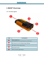
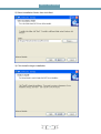
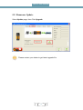
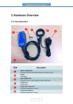
MVCI ® User Manual X-Horse Electronics Co., Ltd. MVCI® User Manual Table of Contents 1. 2. 3. 4. 5. 6. Safety Precautions and Warnings ................................................................................ 3 General Information ...................................................................................................... 4 MVCI® Overview ........................................................................................................... 5 3.1. Tool Description ................................................................................................. 5 3.2. Specifications..................................................................................................... 6 3.3. Accessories Included ......................................................................................... 7 3.4. System Requirements ....................................................................................... 7 3.5. Features ............................................................................................................. 8 Installation..................................................................................................................... 9 MVCI® Configuration Tool ........................................................................................... 12 5.1. Connection Test ............................................................................................... 12 5.2. Firmware Update ............................................................................................. 13 5.3. Language ......................................................................................................... 14 Warranty and Service ................................................................................................. 15 6.1. Limited One Year Warranty ............................................................................. 15 6.2. Service Procedures ......................................................................................... 15 2 MVCI® User Manual 1. Safety Precautions and Warnings To prevent personal injury or damage to vehicles and/or the tool, read this instruction manual first and observe the following safety precautions at a minimum whenever working on a vehicle: Always perform automotive testing in a safe environment. Wear safety eye protection that meets ANSI standards. Keep clothing, hair, hands, tools, test equipment, etc. away from all moving or hot engine parts. Operate the vehicle in a well ventilated work area: Exhaust gases are poisonous. Put blocks in front of the drive wheels and never leave the vehicle unattended while running tests. Use extreme caution when working around the ignition coil, distributor cap, ignition wires and spark plugs. These components create hazardous voltages when the engine is running. Put the transmission in PARK (for automatic transmission) or NEUTRAL (for manual transmission) and make sure the parking brake is engaged. Keep a fire extinguisher suitable for gasoline/chemical/electrical fires nearby. Don’t connect or disconnect any test equipment while the ignition is on or the engine is running. Keep the tool dry, clean, free from oil/water or grease. Use a mild detergent on a clean cloth to clean the outside of the scan tool, when necessary. 3 MVCI® User Manual 2. General Information Thank you for choosing MVCI® Automotive Diagnostic Tool. This manual includes the use of equipment notes, please read this manual carefully before use so that you can correctly use it. © X-Horse Electronics, 2010 All rights reserved. No part of this publication may be reproduced, stored in a retrieval system, or transmitted, in any form, or by any means, mechanical, electronic, photocopying, recording, or otherwise, without the prior written permission of X-Horse Electronics. All copyright and trademarks acknowledged. No patent liability is assumed with respect to the use of the information contained herein. Moreover, because X-Horse Electronics is constantly striving to improve its high-quality products, the information contained in this manual is subject to change without notice. Every precaution has been taken in the preparation of this manual. Nevertheless, X-Horse Electronics assumes no responsibility for errors or omissions. Neither is any liability assumed for damages resulting from the use of the information contained in this publication. 4 MVCI® User Manual 3. MVCI® Overview 3.1. Tool Description ITEM Description ❶ OBD II CONNECTOR ❷ USB CONNECTOR ❸ PC LED ❹ POWER LED ❺ CAR LED Connects the tool to the vehicle’s Data Link connector (DLC). Connects the tool to the PC/Laptop through USB Cable. PC/Laptop Connection Status Indicator. Power Status Indicator. Vehicle Connection Status Indicator. 5 MVCI® User Manual 3.2. Specifications ITEM Description Operating Temperature -20 to 70 °C ( -4 to 158 °F ) Storage Temperature -40 to 85 °C ( -40 to 185 °F ) Diagnostic Interface 16 PIN USB Interface USB 2.0 Power DC 5 V - 36 V Consumption 1W Dimensions Length 95 mm(3.74″) Net Weight 85 g Gross Weight 193 g 6 Width 49 mm(1.93″) Height 28 mm(1.10″) MVCI® User Manual 3.3. Accessories Included ITEM Description User Manual Instructions on tool operations. CD Includes user manual, drivers, and etc. OBD II cable Communicates between tool and vehicle USB cable Communicates between tool and PC/Laptop Carry case A nylon case to store the tool when not in use. 3.4. System Requirements PC/Laptop Minimum Specification Minimum Specification CPU Pentium 3/1GHz or above Recommended Specification Pentium 4/1.6GHz or above Memory(RAM) 256M or above 512M or above HDD 40G or above 60G or above Display 800 x 600 or above 1024 x 768 or above OS Win98/2000/XP/Vista WinXP Port USB USB 7 MVCI® User Manual 3.5. Features Fully SAE J2534 compliant K-Line ISO 9141 KWP 2000 ISO 14230-4 SAE J1850 PWM SAE J1850 VPW CAN 2.0B ISO 11898 CAN ISO 15765-4 SCI SAE J2610 Programmable power supply Able to apply 5V-24V to OBD pins 6,9,11,12,13,14 or AUX 2.5mm stereo connector Able to apply GND to OBD pins 6,9,11,12,13,14,15 or AUX 2.5mm stereo connector RGB status LEDs 8 MVCI® User Manual 4. Installation 1) Click Next 9 MVCI® User Manual 2) Select installation folder, then click Next 3) Click Install to begin installation 10 MVCI® User Manual 4) Installing… 5) Click Finish to exit installation 11 MVCI® User Manual 5. MVCI® Configuration Tool 5.1. Connection Test Select Connection page, then Click Connect Connection status will show as: 12 MVCI® User Manual 5.2. Firmware Update Select Update page, then Click Upgrade Please contact your dealer to get latest upgrade file. 13 MVCI® User Manual 5.3. Language Select Option page, choose your preferred language. 14 MVCI® User Manual 6. Warranty and Service 6.1. Limited One Year Warranty X-Horse warrants to its customers that this product will be free from all defects in materials and workmanship for a period of one(1) year from the date of the original purchase, subject to the following terms and conditions: This warranty does not apply to damages caused by improper use, accident, flood, lightning, or if the product was altered or repaired by anyone other than the Manufacturer’s Service Center. X-Horse shall not be liable for any incidental or consequential damages arising from the use, misuse, or mounting of the tool. Some states do not allow limitations on how long an implied warranty lasts, so the above limitations may not apply to you. All information in this manual is based on the latest information available at the time of publication and no warranty can be made for its accuracy or completeness. X-Horse reserves the right to make changes at any time without notice. 6.2. Service Procedures If you have any questions, please contact your distributor. If it becomes necessary to return the tool for repair, contact your distributor for more information. 15