1
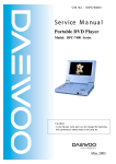
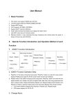
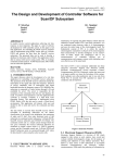
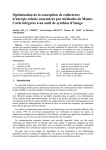
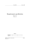
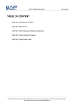
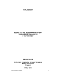
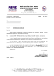
International Journal of Computer Applications (0975 – 8887)
National Conference on Emerging Trends in Advanced Communication Technologies (NCETACT-2015)
Study on I2C Protocol for Implementation on FPGA
Shital Mahajan
Department of Electronics and Telecommunication Engineering
(VLSI & Embedded Systems)
D. Y. College of Engineering,
Akurdi, Pune
ABSTRACT
In this study, having a study of implementation of I2C
protocol on FPGA. This study of project also contains
learning anew platforms, tools like I2C bus configuration
Xilinx 14.1, Verilog. I2C protocol has easy communication
without any data loss. It also has high speed compared to
other protocols. I2C uses only two wire for communication. It
also increases data transfer rate. I2C is used in data
observation for accuracy and efficiency. The design method
will be developed in Verilog, simulated on Xilinx 14.1 and
will be implemented on FPGA board.
General Terms
Protocol, Coding, Interfacing.
Keywords
IC24C02, FPGA, I2C, master, serial data communication,
slave, Spartan 3, Xilinx
1. INTRODUCTION
In the field of serial data communication, there are some
protocols like RS-232,RS-422, RS-485, SPI (Serial peripheral
interface), and For interfacing high speed and low speed
peripherals there is Micro wire. These protocols require
number of pin connections in the IC(Integrated Circuit) for
serial data communication to be taken place, There is a
requirement of less amount of pin connection for serial data
transfer as the physical size of IC have decreased over the
years. Protocols like USB/SPI/Micro wire and also mostly
UARTS are all only ‘one point to one point’ data transfer bus
systems. They all use multiplexing of the data path and to
send messages to service multiple devices. To overcome the
same problem Phillips introduced the I2C protocol which
needs only two lines to communicate.
The I2C protocol was developed by Philips Semiconductors
with purpose for allowing faster devices to communicate with
slower devices As well as also allow devices to communicate
with each other above a serial data bus without any data loss.
In this there is a model of I2C bus controller. This I2C
controller will be designed using verilog in xilink 14.1 and
targeted in Spartan-3.
In this system, presents there is an experimental design and
implementation of serial data communication by using I2C
master and slave bus controller with the help of a FPGA. The
I2C master will initiate the data transmission and acceptable
slave responds to it. Here 24C02 IC as a slave is to be
implemented. Also the ADC, EEPROM, and RTC can be used
to interface for communication among Slave and Master. So
as It remains for minimizing system-level interconnect.
Moreover transmitting information over the I2C bus will
increase system.
2. DESIGN AND IMPLEMANTATION
STUDY
A] I2C protocol: This is also known as Inter Integrated Circuit
Protocol, i.e. it is helpful when there is a need of
Communication between two ICs which are not present in
common Board. It is very simple to design. It needs only 2
wires for the communication Process. Hence this Protocol is
also known as 2-Wire Communication Protocol. The I2C
protocol was developed by Philips Semiconductors with
purpose for allowing faster devices to communicate with
slower devices as well as also allow devices to communicate
with each other above a serial data bus without any data
loss.[4][5]
2.1 I2C Bus Specification
The I2C Controller Bus is a two-wire, bi-directional serial bus
that provides a simple and efficient method of data
transmission over a short distance between many devices. I2C
provides good support for communication with various slow,
on-board peripheral devices that are accessed intermittently,
while being extremely modest in its hardware resource needs.
It is a simple, low bandwidth, short distance protocol. I2C is
easy to use to link multiple devices together since it has a
built-in address [1].The two I2C signals are serial data (SDA)
and serial Clock (SCL) as shown in Figure. The device that
initiates a transaction on the I2C bus is termed the master. The
master normally controls the clock signal. A device being
addressed by the master is called a slave. [1][2] The following
diagram shows I2C bus configuration using masters and
slaves.
Figure 1: I2C bus configuration using masters and slaves
The I2C protocol supports multiple masters, but most of the
system designs include only one. There may be one or more
slaves on the bus. Anyone of masters and slaves can receive
and transmit data bytes at a time. Standard I2C devices work
up to 100Kbps, while for fast-mode devices operate at up to
400Kbps. Most of the fast-mode devices are available today
support 400Kbps operation. Higher-speed operation may
allow I2C to have with the rising demand for bandwidth in
multimedia as well as other applications. [1]
2.2 I2C Characteristics
The ideal architecture with I2C has the characteristics high
performance,
flexibility,
easy
upgradability,
Low
development cost[3]. The SDA and SCL lines are bidirectional lines connected to a positive voltage supply
5
International Journal of Computer Applications (0975 – 8887)
National Conference on Emerging Trends in Advanced Communication Technologies (NCETACT-2015)
through a pull up resistor. The bus is free when these lines are
`high'. The data on the SDA line is valid only when the SCL
line is `high'. Change of data is allowed when SCL line
becomes `low'. During data transfer, the master generates the
START and STOP conditions, which are unique conditions
and are shown in Figure [2].
Figure 2: START and STOP conditions
2.3 I2C Bus Controller Design
I2C protocol consists of four parts 1)START signal
generation,2) Slave address transfer, 3) Data transfer,4) STOP
signal generation[1]. I2C controller is to be implemented. It is
for minimizing system level interconnects. Also transmitting
the information over I2C bus will improve system
performance. Following is the block diagram of
communication between Master and Slave.
FPGA will be used for the project as it has parallel processing
feature. This project will demonstrate how I2C Master
Controller (Master) transmits and receives data to and from
the Slave. For the implementation and interfacing of I2C
master controller to slave over FPGA Verilog language will
be used. This will simplifies the system level design. In this
study, an experimental design and implementation of serial
data communication by using I2C master and slave bus
controller will be designed with the help of an FPGA.[6] This
module will be designed in Verilog HDL. The design will be
created using Xilinx platform studio 14.1. It can be used in the
applications such as embedded system, mobile phones,
motherboard, set top boxes, DVD, PDA's or any other
electronic devices.
Figure 4 is the block diagram of I2C as a master and 24C02
IC as a slave of proposed System. In which slave i.e. memory
IC 24C02 is connected to master i.e. FPGA.[6][7] In the I2C
master controller, I2C start/stop is a first block in which start
and stop condition will be generated. At the time of SCL line
is high, there should be two conditions of SDA line i.e. low to
high and high to low. So at SDA line is low to high then a
start condition will be generated and at high to low then stop
condition will be generated. Arbitration unit monitors whether
bus is in ideal condition or not. If SDA and SCL both are high
then bus is also high that means bus is in ideal condition.
Microprocessor will be connected to switches and LEDs. I2C
controller state machine controls all units. I2C Synchronizer
and I2C clock generator will set frequency between 100Kbps
to 400Kbps.
3. CONCLUSION
Figure 3: I2C bus architecture.
It consists of a master and a slave connected using I2C bus.
The SDA line is connected to a positive supply voltage
through a pull up resistor. The SCL line is not connected to a
pull up resistor as there is only one master. For designing the
I2C master controller a finite state machine (FSM) is required.
We can easily implement finite state machine by writing
VHDL or Verilog code [1].
For this study I2C is to be used due to its simplicity of design
and easy maintenance. Also has the characteristics i.e. high
performance, flexibility, low development cost.FPGA will be
used for the project as it has parallel processing feature. This
will simplifies the system level design an experimental design
and implementation of serial data communication by using
I2C master and slave bus controller will be designed with the
help of an FPGA. This project will be designed in Verilog
HDL. The design will be created using Xilinx platform studio
14.1. With the help of this designed module the applications
can be designed. It can be used in the applications such as
embedded system, mobile phones, motherboard, set top
boxes, DVD, PDA’s or any other electronic devices.
4. REFERENCES
[1] B. H. Soni, Mr. J. J. Patel Design and implementation of
i2c bus controller using verilog. Journal of Information,
Knowledge and Research in Electronics and
Communication Engineering, 02:520, 2012.
[2] Um10204 i2c -bus specification and user manual Rev.4
[3] JayantMankar,
ChaitaliDarode,
KomalTrivedi,
MadhuraKanoje, PrachiShahare. REVIEW OF I2C
PROTOCOL. International Journal of Research in
Advent Technology, Volume 2, Issue 1, January
2014,474
[4] THE I2C BUS SPECIFICATION VERSION 2.1
January, 2000, Philips Semiconductors.
[5] Philips Semiconductor. I2c bus specification. Version
2.1, January 2000.
Figure 4: The I2C Master Controller Block Diagram
IJCATM : www.ijcaonline.org
[6] Jai Karan Singh. Design and implementation of i2c
master controller on fpga using vhdl. Aug-Sep 2012
6