Transcript
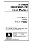
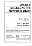
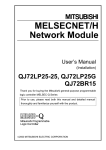
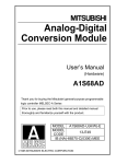
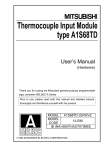
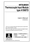
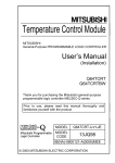
13JT24
IB-0800151-A (0012) MEE
©2000 MITSUBISHI ELECTRIC CORPORATION
Part name
(Read these precautions before using.)
When using Mitsubishi equipment, thoroughly read this manual and the associated
manuals introduced in the manual. Also pay careful attention to safety and handle the
module properly.
These precautions apply only to Mitsubishi equipment. Refer to the user’s manual of the
CPU module to use for a description of the PLC system safety precautions.
These SAFETY PRECAUTIONS classify the safety precautions into two
categories: "DANGER" and "CAUTION".
DANGER
CAUTION
Procedures which may lead to a dangerous condition and
cause death or serious injury if not carried out properly.
Procedures which may lead to a dangerous condition and
cause superficial to medium injury, or physical damage only,
if not carried out properly.
Depending on circumstances, procedures indicated by
CAUTION may also be linked
to serious results.
In any case, it is important to follow the directions for usage.
Store this manual in a safe place so that you can take it out and read it whenever
necessary. Always forward it to the end user.
[DESIGN PRECAUTIONS]
CAUTION
• Do not bunch the control wires or communication cables with the main circuit or power
wires, or install them close to each other.
They should be installed 100 mm (3.94 inch) or more from each other.
Not doing so could result in noise that may cause malfunction.
[INSTALLATION PRECAUTIONS]
CAUTION
• Use the PLC in an environment that meets the general specifications given in the User's
Manual of the CPU module being used.
Using this PLC in an environment outside the range of the general specifications may cause
electric shock, fire, malfunction, and damage to or deterioration of the product.
• When installing the module, securely insert the module fixing tabs into the mounting holes of the
base unit while pressing the installation lever located a t the bottom of the module downward.
Improper installation may result in malfunction , breakdown or the module coming loose and
dropping.
Securely fix the module with screws if it is subject to vibration during use.
• Tighten the screws within the range of specified torque.
If the screws are loose, it may cause the module to fallout, short circuits, or malfunction.
If the screws are tightened too much, it may cause damage to the screw and/or the module,
resulting in fallout, short circuits or malfunction.
• Switch all phases of the external power supply off when mounting or removing the module.
Not doing so may cause damage to the module.
• Do not directly touch the conductive area or electronic components of the module.
Doing so may cause malfunction or failure in the module.
[WIRING PRECAUTIONS]
Type
Analog output
I/O characteristics
maximum resolution
Normal
Digital input
resolution value
mode
Maximum
resolution
High
Digital input
resolution value
mode
Maximum
resolution
Accuracy
Ambient
(Accuracy in temperature
respect to
25 ± 5 °C
maximum
Ambient
analog output temperature
value)
0 to 55 °C
Conversion speed
– 16000 – 12000
0 to 12000
to 16000 to 12000
0.333 0.625 mV 0.333 mV 1.66 µ A
1.33 µ A
mV
ERROR
1
3
1
2
3
4
5
6
7
8
3)
4)
Manual No. (Model code)
SH-080054
(13JR02)
4
5
6
7
8
9
9
10
10
11
12
13
14
15
16
17
18
External wiring
FG
*1
D/A
conversion
11
12
13
14
15
16
CH.2
CH.3
CH.4
CH.5
CH.6
CH.7
CH.8
CH.1
COM
V+
CH.2
COM
V+
CH.3
COM
V+
CH.4
COM
V+
CH.5
COM
V+
CH.6
COM
V+
CH.7
COM
V+
CH.8
COM
17
24 V
18
24 G
90 (3.54)
1 kW
to
1 MW
V+
+15 V
10.5
(0.41)
+24 V
DC/DC
converter
24V
24G
FG
Filter
–15 V
Warranty
*1
D/A
conversion
*2
Motor drive module, etc.
0W
to
600W
I+
COM
GND
+15V
+24V
24 V DC
DC/DC
converter
24V
24G
FG
Filter
–15V
A.G
Switch setting for intelligent functional module
The settings for the intelligent function module are performed using the I/O allocation
settings for the GX Developer. It can be easy to set by inputting using hexadecimal-4
digits.
Output range setting
(CH.1 to CH.4)
Analog output range
4 to 20 mA
0 to 20 mA
1 to 5 V
0 to 5 V
– 10 to 10 V
User range setting
COM
H
I+
COM
I+
CH4 CH3 CH2 CH1
Switch 2
Output range setting
(CH.5 to CH.8)
COM
H
I+
COM
Switch 3 *2
b8
b15
0
COM
I+
Output range setting value
0 H *1
1H
2H
3H
4H
FH
CH8 CH7 CH6 CH5
I+
to
b7
b6
b5
b4
b3
b2
b1
b0
0
HOLD/CLEAR function setting
0 : CLEAR
1 : HOLD
CH8 CH7 CH6 CH5 CH4 CH3 CH2 CH1
Switch 4
H
COM
I+
00H
: Normal mode (non-synchronized)
01 to FFH : Synchronized output mode
COM
0H
:Normal resolution mode
1 to FH : High resolution mode
0H
: Normal mode
(D/A conversion processing)
1 to FH : Offset/gain setting mode
I+
COM
Switch 5
0 : Fixed
Mitsubishi Electric shall not be liable for any loss caused by reasons for which Mitsubishi is not held
accountable, lost business opportunities or unrealized gain on the customer's side resulting from failure of
the product, or any other damage, secondary disaster, accident, damage to equipment other than the
product or disruption of other business operations arising out of special circumstances which may or may
not have been predicted at Mitsubishi.
For safe use of the product
"
"
"
*1 Use a twisted two core shielded wire for the power wire.
*2 If there is noise or ripples in the external wiring, connect a 0.1 to 0.47 m F25V
condenser between the V+/I+ terminal and COM.
Switch 1
FG terminal L-shaped
metal fitting
FG terminal screw (M3 screw)
A.G
Setting
I+
7.4
(0.29)
unit (mm (in.))
(2) Q68DAI
A.G
27.4
(1.08)
GND
Q68DAI
V+
Motor drive module, etc.
24 V DC
Signal name
CH.1
*2
COM
A.G
Q68DAV
1
2
3
4
5
6
7
8
9
10
11
12
13
14
15
16
17
18
(1) Q68DAV
5.3
number
RUN
FG
Related Manual
IN 24VDC
5.2
80 µ s/ channel
2
The following manuals are also related to this product. Order them if necessary.
Point
If it is difficult to wire FG terminals due to the limited installation space, use FG terminal L-shaped metal fitting.
Within ± 0.3 % (Voltage : ± 30mV, Current : ± 60µA)
Terminal
Q68DA
ERROR
Wiring precautions
Within ± 0.1 % (Voltage : ± 10mV, Current : ± 20µA)
This section explains the names of the components for the D/A converter module.
1)
2)
RUN
(1) Use separate cables for the external output signal or external power supply
for the AC and D/A converter modules. Take steps to prevent the AC side
from being affected by surge or inductance.
(2) Ground one point of the shield for shielded wires or shielded cables.
– 12000
to 12000
0.83 µ A
3. Part Names
IN 24VDC
Manual Name
0 to 12000
0.416
mV
5.1
Q68DAI
8 points (8 channels)
16-bit signed binary (normal resolution
16-bit signed binary (normal
mode: –4096 to 4095,
resolution mode: –4096 to 4095,
high resolution mode:–12288 to
high resolution mode:–12288 to
12287)
12287, –16384 to 16383)
– 10 to 10V DC (External load
0 to 20 mA DC (External load
resistance 1 k Ω to 1 M Ω)
resistance 0 Ω to 600 Ω)
Analog output range
Analog output range
0 to 5 V 1 to 5 V – 10 to
Users 0 to 20 mA 4 to 20 mA Users
10 V
range
range
setting
setting
0 to 4000
– 4000 to 4000
0 to 4000
– 4000 to
4000
1.25 mV 1.0 mV 2.5mV 0.75mV
5µA
4µA
1.5 µ A
Q68DA
36 to 48 N · cm
42 to 58 N · cm
66 to 89 N · cm
42 to 58 N · cm
5. Wiring
Type
Q68DAV
Q68DAI
Item
Absolute maximum output
± 12 V
21 mA
Output short circuit protection
Available
Insulation method
Between I/O terminal and PLC power supply
: Photocoupler insulation
Between output channels
: Not insulated
Between external supply power and analog output : Not insulated
Number of occupied points
16 points
Connecting terminals
18 points terminal block
Applicable wire size
0.3 to 0.75 mm2
Applicable solderless terminals
Other terminals than FG:R1.25 - 3
(A solderless terminals with sleeves cannot be used)
FG terminal:R1.25-3, 1.25-YS3, RAV1.25-3, V1.25-YS3A
External supply power
24 V DC + 20 %, – 15 %
Ripple, spike within 500 mVP -P
Inrush current : 3.3A, within 70µs
Inrush current : 3.1A, within 75µs
0.19 A
0.28 A
Internal current consumption
0.39 A
0.38 A
(5 V DC)
Weight
0.18 kg
• Always ground the FG terminal for the PLC.
There is a risk of electric shock or malfunction.
• When turning on the power and operating the module after wiring is completed, always attach
the terminal cover that comes with the product.
There is a risk of electric shock if the terminal cover is not attached.
• Tighten the terminal screws within the range of specified torque.
If the terminal screws are loose, it may result in short circuits or malfunction.
If the terminal screws are tightened too much, it may cause damage to the screw and/or the
module, resulting in short circuits or malfunction.
• Be careful not to let foreign matters such as sawdust or wire chips get inside the module.
These may cause fires, failure or malfunction.
• The top surface of the module is covered with protective film to prevent foreign objects such as
cable offcuts from entering the module when wiring.
Do not remove this film until the wiring is complete.
Before operating the system, be sure to remove the film to provide adequate heat ventilation.
D/A Converter Module User's Manual
Q68DAV
6. External Dimensions
Tightening torque
Module mounting screw (M3 screw)
Terminal block terminal screw (M3 screw)
Terminal block mounting screw (M3.5 screw)
FG terminal screw (M3 screw)
The specifications for the D/A converter module are shown in the following
table. For general specifications, refer to the operation manual for the CPU
module being used.
CAUTION
About This Manual
Screw location
1
1
2. Specifications
Item
Number of analog outputs
Digital input
(1) Do not drop the module or cause it to receive strong impact.
(2) Tighten the terminal screws for the module to the specified torque shown below.
Insufficient tightening torque could result in shorts, failures or malfunction.
Qty.
Q68DAV/Q68DAI Model Digital-Analog module
FG terminal L-shaped metal fitting
SAFETY PRECAUTIONS
4. Handling Precautions
2
(0.08)
Q- 68D/A -U-H-JE
4)
8.5
(Hardware)
Output range setting value can be set within the ranges described below
depending on the D/A converter module's model name.
! Q68DAV .........0H, 2H to 4H, FH
*1: The module activates at the analog output range within 1
to 5V, when 0H is set.
! Q68DAI ...........0H, 1H, FH
*2: Switch 3 is set at decimal unit.
Setting is comparatively easier when the input type is change to decimal.
(0.33)
User's Manual
MODEL
MODEL
Number
3)
This manual explains specifications and the names of the components for the
Q68DAV type D/A converter module (hereafter Q68DAV) and the Q68DAI
type D/A converter module (hereafter Q68DAI) which are used in combination
with the MELSEC-Q Series CPU module. In this manual, both the Q68DAV
and Q68DAI are referred to as D/A converter modules.
After unpacking, confirm that the following products are enclosed.
Description
Displays the operating status of the D/A converter module.
On
: Normal operation
Flashing : During offset/gain setting mode
Off
: 5V power supply interrupted or watch dog timer error
ERROR LED
Displays the error status of the D/A converter module.
On
: Error
Off
: Normal operation
Flashing : Error in switch settings
Switch No. 5 of the intelligent function module has been
set to a value other than "0".
External power supply This is the terminal for connecting the 24 V DC external power
terminal
supply.
FG terminal
Terminal for frame ground
2)
1. Overview
Name
RUN LED
98 (3.86)
Prior to use, please read both this manual and detailed manual thoroughly
and familiarize yourself with the product.
1)
3.7
(0.15)
Thank you for buying the Mitsubishi general-purpose programmable logic
controller MELSEC Q Series.
Number
6.7
(0.26)
Q68DAV, Q68DAI
D/A Converter Module
Conformation to the EMC Directive and Low Voltage Instruction
When complying with EMC Directives and Low-Voltage Directives by assembling a
Mitsubishi PLC compatible with EMC Directive and Low-Voltage Directives into the user
product, refer to Chapter 3 "EMC Directives and Low-Voltage Directives" in the User's
Manual (Hardware Section) for the CPU module being used. The CE logo is printed on
the rating plate on the main body of the PLC that conforms to the EMC directive and low
voltage instruction.
This product is manufactured as a general-purpose product intended for general industrial use only. It is
not designed nor manufactured for use in an equipment or system affecting human lives.
If you are considering to use this product in equipment or systems for nuclear power generation, power
generation, aerospace, medical or passenger transport applications, consult our sales representatives.
This product is manufactured under our strict quality control system. However, if the product is used in
the intended facility in such a way that a failure of the product may lead to serious accident or loss,
incorporate backup or fail-safe functions into the system design.
Country/Region Sales office/Tel
U.S.A
Mitsubishi Electric Automation Inc.
500 Corporate Woods Parkway Vernon
Hills, IL 60061
Tel : 1-847-478-2100
Brazil
MELCO-TEC Rep. Com.e Assessoria
Tecnica Ltda.
Av. Rio Branco, 123-15 ,and S/1507,
Rio de Janeiro, RJ CEP 20040-005,
Brazil
Tel : 55-21-221-8343
Germany
Mitsubishi Electric Europe B.V. German
Branch
Gothaer Strasse 8 D-40880 Ratingen,
GERMANY
Tel : 49-2102-486-0
U.K
Mitsubishi Electric Europe B.V. UK
Branch
Travellers Lane, Hatfield, Herts., AL10
8XB,UK
Tel : 44-1707-276100
Italy
Mitsubishi Electric Europe B.V. Italian
Branch
Centro Dir. Colleoni, Pal. Perseo - Ingr.2
Via Paracelso 12, 20041 Agrate B.,
Milano, Italy
Tel:39-039-6053301
Spain
Mitsubishi Electric Europe B.V. Spanish
Branch
Pol. Ind. "Can Magi"- C/.Joan Buscalla,
2-4-A.C.420
08190 Sant Cugat del Valles, Barcelona,
Spain
Tel:34-935-653135
South Africa
MSA Manufacturing (Pty) Ltd.
P O Box 39733 Bramley 201 8
Johannesburg, South Africa
Tel : 27-11-444-8080
Hong Kong
Ryoden International Ltd.
10th Floor, Manulife Tower, 169 Electric
Road, North Point, HongKong
Tel : 852-2887-8870
Country/Region Sales office/Tel
China
Ryoden International Shanghai Ltd.
3F Block5 Building Automation
Instrumentation Plaza 103 Cao Bao Rd.
Shanghai 200233 China
Tel : 86-21-6475-3228
Taiwan
Setsuyo Enterprise Co., Ltd.
6F., No.105 Wu-Kung 3rd.RD, Wu-Ku
Hsiang, Taipei Hsine, Taiwan R.O.C.
Tel : 886-2-2299-2499
Korea
HAN NEUNG TECHNO CO.,LTD.
1F Dong Seo Game Channel Bldg.,
660-11, Deungchon-dong Kangsec-ku,
Seoul, Korea
Tel : 82-2-3668-6567
Singapore
Mitsubishi Electric Asia Pte, Ltd.
307 ALEXANDRA ROAD #05-01/02,
MITSUBISHI ELECTRIC BUILDING
SINGAPORE 159943
Tel : 65-473-2480
Thailand
F. A. Tech Co.,Ltd.
898/28,29,30 S.V.City Building,Office
Tower 2,Floor 17-18 Rama 3 Road,
Bangkpongpang, Yannawa,
Bangkok 10120
Tel : 66-2-682-6522
Indonesia
P.T. Autoteknindo SUMBER MAKMUR
Jl. Muara Karang Selatan Block A Utara
No.1 Kav. No.11 Kawasan Industri/
Pergudangan Jakarta - Utara 14440
Tel : 62-21-663-0833
India
Messung Systems Put,Ltd.
Electronic Sadan NO:111 Unit No15,
M.I.D.C BHOSARI,PUNE-411026
Tel : 91-20-7128927
Australia
Mitsubishi Electric Australia Pty. Ltd.
348 Victoria Road, PostalBag, No 2,
Rydalmere, N.S.W 2116, Australia
Tel : 61-2-9684-7777
HEAD OFFICE:MITSUBISHI DENKI BLDG MARUNOUCHI TOKYO 100-8310 TELEX:J24532 CABLE MELCO TOKYO
NAGOYA WORKS:1-14, YADA-MINAMI 5, HIGASHI-KU, NAGOYA, JAPAN
When exported from Japan, this manual does not require application to the Ministry
of International Trade and Industry for service transaction permission.
Specifications subject to change without notice.
Printed in Japan on recycled paper.