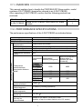
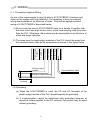
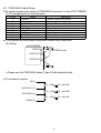
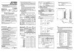
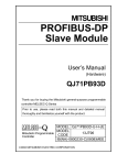
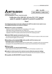
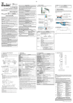
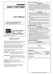
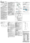
1
PROFIBUS-DP Slave Module User’s Manual (Hardware) A1SJ71PB93D Thank you for buying the Mitsubishi general-purpose programmable logic controller MELSEC Series Prior to use, please read both this manual and detailed manual thoroughly and familiarize yourself with the product. MODEL A1SJ71PB93D-U-H MODEL 13JT73 CODE IB(NA)-0800205-A(0109)MEE 2001 MITSUBISHI ELECTRIC CORPORATION • SAFETY PRECAUTIONS • (Read these precautions before using.) Before using this product, please read this manual and the relevant manuals introduced in this manual carefully and pay full attention to safety to handle the product correctly. The instructions given in this manual are concerned with this product. For the safety instructions of the programmable controller system, please read the CPU module user's manual. In this manual, the safety instructions are ranked as "DANGER" and "CAUTION". DANGER Procedures which may lead to a dangerous condition and cause death or serious injury, if not carried out properly. CAUTION Procedures which may lead to a dangerous condition and cause superficial to medium injury, or physical damage only, if not carried out properly. Note that the CAUTION level may lead to a serious consequence according to the circumstances. Always follow the instructions of both levels because they are important to personal safety. Please save this manual to make it accessible when required and always forward it to the end user. [INSTALLATION PRECAUTIONS] CAUTION • Use the PLC in an environment that meets the general specifications contained in the CPU user's manual. Using this PLC in an environment outside the range of the general specifications may cause electric shock, fire, malfunction, and damage to or deterioration of the product. • Load the module by securely inserting the module fixing hook at the bottom of the module into the fixing hole of the base unit. Always screw the module to the base unit to the specified torque. • Tighten the screws within the range of specified torque. If the screws are loose, it may cause the module to fallout, short circuits, or malfunction. If the screws are tightened too much, it may cause damage to the screw and/or the module, resulting in fallout, short circuits or malfunction. • Switch all phases of the external power supply off when mounting or removing the module. Not ding so may cause electric shock or damage to the module. • Do not touch the conductive area or electric parts of the module. Doing so may cause module malfunctioning or breakdowns. A-1 [WIRING PRECAUTIONS] CAUTION • Switch all phases of the external power supply of the PLC system off before connecting the PROFIBUS cable. If you not switch off the external power supply, it will cause failure or malfunction of the module. • Be careful not to let foreign matter such as filings or wire chips get inside the module. These can cause fire, breakdowns and malfunctioning. • The PROFIBUS cable which is connected to the module must be protected with a duct or secured in position with clamps. Unless the cable is thus protected or secured, the module or the cable could be damaged when the cable swings, moves or it is strained with careless pulls, or it could cause malfunction when the cable contacts with any undesirable objects. • When disconnecting the PROFIBUS cable from the module, do not pull by holding the cable section. To disconnect the cable, make sure to hold the connector which is coupled with the module. Do not attempt to pull the cable to disconnect it from the module. It could damage the module or the cable, or cause malfunction due to a poor contact of the cable. Revisions The manual number is given on the bottom left of the back cover. Print Date Manual Number Sep., 2001 IB(NA)-0800205-A First printing Revision This manual confers no industrial property rights or any rights of any other kind, nor does it confer any patent licenses. Mitsubishi Electric Corporation cannot be held responsible for any problems involving industrial property rights which may occur as a result of using the contents noted in this manual. 2001 MITSUBISHI ELECTRIC CORPORATION A-2 CONTENTS SAFETY PRECAUTIONS .............................................................................. A-1 REVISIONS ................................................................................................... A-2 About the Manuals ......................................................................................... A-3 Conformation to the EMC Directive and Low Voltage Instruction .................. A-3 1. OVERVIEW ...................................................................................................1 2. PERFORMANCE SPECIFICATIONS ............................................................1 3. INSTALLATION .............................................................................................2 3.1 Handling Precautions ...............................................................................2 4. PART NAMES AND SETTINGS ....................................................................3 5. WIRING..........................................................................................................5 5.1 Precautions Against Wiring ......................................................................5 5.2 PROFIBUS Cable Wiring .........................................................................6 6. OUTLINE DRAWINGS...................................................................................7 About the Manuals The following table lists manuals regarding this product. Use this table to order necessary manuals respective to the functions used. Related Manuals Manual No. (Model code) Manual name A1SJ71PB93D type PROFIBUS-DP Slave Module User's Manual SH-080195 (13JR47) Conformation to the EMC Directive and Low Voltage Instruction For details on making Mitsubishi PLC conform to the EMC directive and low voltage instruction when installing it in your product, please refer to Chapter 3, "EMC Directive and Low Voltage Instruction" of the User's Manual (Hardware) for the CPU module to use. The CE logo is printed on the rating plate on the main body of the PLC that conforms to the EMC directive and low voltage instruction. A-3 1. OVERVIEW This manual explains how to handle the PROFIBUS-DP Slave module, model numbers A1SJ71PB93D (hereinafter referred to as A1SJ71PB93D). After unpacking A1SJ71PB93D, confirm that the following products are enclosed. Model number A1SJ71PB93D Description Model A1SJ71PB93D PROFIBUS-DP Slave module Quantity 1 2. PERFORMANCE SPECIFICATIONS The performance specifications of the A1SJ71PB93D are indicated below. Transmission specifications Item Model PROFIBUS-DP station type Electrical standards and characteristics Medium Network configuration Data link method Transmission encoding method Transmission speed/maximum transmission distance 1 2 Maximum number of repeaters/network Maximum number of stations/segment Number of connection nodes/segments Station numbers that may be set Max. number of data that may be communicated Specifications A1SJ71PB93D Slave station Complies with EIA-RS485 Shielded twisted cable (Type A) Bus (however, tree type when a repeater is used) Polling method NRZ Maximum transmission Transmission Transmission distance when 3 speed distance [m/segment] repeaters are used [m/network] 9.6 [kbps] 19.2 [kbps] 1200 4800 45.45 [kbps] 93.75 [kbps] 187.5 [kbps] 1000 4000 500 [kbps] 400 1600 1500 [kbps] 200 800 3 [Mbps] 6 [Mbps] 100 400 12 [Mbps] 2 3 units 32 stations (including repeaters) 32 0 to 125 3 Number of I/O data is 192 words in total. (Number of input or output data is up to 122 words.) 1 Item Flash ROM write count Number of occupied I/O 5VDC Internal power consumption (A) External dimensions (mm) Weight (kg) Specifications Max. 10000 times 32 points (I/O assignment : 32 Special points) 0.36 130(H) 34.5(W) 0.18 93.6(D) 1 Transmission speed control within +/- 0.3% (EN50170Volume2 compliant) 2 Distance that the transmission distance can be expanded by (m/network) using repeaters Transmission distance (m/network) = (number of repeaters + 1) transmission distance (m/segment) For the general specifications, noise immunity, withstand voltage, insulation resistance and others in the PLC system using this module, refer to the used CPU module user’s manual. 3. INSTALLATION The following section explains the precautions when handling the A1SJ71PB93D, from the time they are unpacked until they are installed. For more details on the module installation, see the user's manual for the PLC CPU used. 3.1 Handling Precautions (1) Do not drop the module case or subject it to heavy impact since it is made of resin. (2) Do not remove the PCB of each module from its case. This may cause a failure in the module. (3) Be careful not to let foreign objects such as wire burrs enter the module during wiring. In the event any foreign object enters, remove it immediately. (4) Tighten the module mounting screws and connector mounting screws using torque within the following ranges. Screw location Module mounting screws (M4 screws) PROFIBUS cable connector mounting screws (#4 - 40UCN) Tightening torque range 78.4 to 117.6 N • cm 20 to 28 N • cm 2 4. PART NAMES AND SETTINGS Following is an explanation of the A1SJ71PB93D part names and settings. A1SJ71PB93D TEST B6 B5 S B4 T. B3 N B2 O B1 . B0 RUN ERR. SYNC FREEZE DIA BF (a) PROFIBUS I/F (b) A1SJ71PB93D 3 No. Name (a) LED Description Displays the A1SJ71PB93D status. Name Display description RUN Displays the A1SJ71PB93D operation status. On: Normal Off: Module WDT error occurrence ERR. On: Parameter setting error or module error occurrence Off: Normal SYNC On: During SYNC mode FREEZE On: During FREEZE mode DIA On: During extended fault notification processing BF On: Before data communication or communication error detected Off: During data communication TEST On: During execution of self-diagnostics B6 to B0 Indicate the station number of the host in binary. Example: Station No. 85 (55H) Remark B6 B5 B4 B3 B2 B1 B0 (b) PROFIBUS Connector for connecting the table for the PROFIBUS-DP interface network. 1 connector 1: For the connector type, use a male D-Sub 9 pin. The PROFIBUS cable must be created by the user. (for information regarding the cable wiring, refer to Item 5.2.) The size of the screw which can be used for the connector is #4-40 UNC. 4 5. WIRING 5.1 Precautions Against Wiring As one of the requirements to give full play to A1SJ71PB93D’s functions and make up the system with high reliability, it is necessary to have an external wiring unsusceptible to an influence of noise. Precautions against external wiring of A1SJ71PB93D is described below. (1) Do not route the wire of A1SJ71PB93D close to or bundle it together with the main circuit and high-tension lines, or the load-carrying lines from other than the PLC. Otherwise, the module may be susceptible to an influence of noise and surge induction. Wiring of input module A1SJ71PB93D Output module Output module Input module Input module PLC CPU Power supply module (2) The wires from the input/output modules of the PLC should be away from the communication cable as far as possible as shown in the figure below. Communication cable Wiring of output module Shielded covering (3) Grounding (a) When the A1SJ71PB93D is used, the FG and LG terminals of the power supply module of the PLC should basically be grounded. (b) If communication cannot be performed after grounding because of abnormal voltage applied to the FG terminal, the module may be used without grounding. 5 5.2 PROFIBUS Cable Wiring This section explains the wiring to PROFIBUS connector for the A1SJ71PB93D (1) Pin assignments for the connector Pin No. 1 2 3 4 5 6 7 8 9 Name Application Shield, Protective Ground — Receive/Transmit Data-P — Data Ground Voltage-Plus — Receive/Transmit Data-N — SHIELD Vacancy RxD/TxD-P Vacancy DGND 1 VP 1 Vacancy RxD/TxD-N Vacancy 1 The signals are used when termination resistors are connected. (2) Wiring A1SJ71PB93D 1 SHIELD RxD/TxD-P RxD/TxD-N 3 PROFIBUS cable 8 • Please use the PROFIBUS cable (Type A) with braided shield. (3) Termination resistor VP (6) Ru = 390 2%, min1/4W RtA = 220 2%, min1/4W Rd = 390 2%, min1/4W RxD/TxD-P (3) RxD/TxD-N (8) DGND (5) 6 6. OUTLINE DRAWINGS A1SJ71PB93D TEST B6 B5 S B4 T. B3 N B2 O B1 . B0 RUN ERR. 130 (5.12) SYNC FREEZE DIA BF PROFIBUS I/F A1SJ71PB93D 6.5 (0.26) 93.6 (3.69) 4 (0.16) 34.5 (1.36) Unit : mm (inch) 7 Warranty Mitsubishi will not be held liable for damage caused by factors found not to be the cause of Mitsubishi; machine damage or lost profits caused by faults in the Mitsubishi products; damage, secondary damage, accident compensation caused by special factors unpredictable by Mitsubishi; damages to products other than Mitsubishi products; and to other duties. For safe use ! This product has been manufactured as a general-purpose part for general industries, and has not been designed or manufactured to be incorporated in a device or system used in purposes related to human life. ! Before using the product for special purposes such as nuclear power, electric power, aerospace, medicine or passenger movement vehicles, consult with Mitsubishi. ! This product has been manufactured under strict quality control. However, when installing the product where major accidents or losses could occur if the product fails, install appropriate backup or failsafe functions in the system. Country/Region Sales office/Tel U.S.A Mitsubishi Electric Automation Inc. 500 Corporate Woods Parkway Vernon Hills, IL 60061 Tel : 1-847-478-2100 Brazil MELCO-TEC Rep. Com.e Assessoria Tecnica Ltda. Av. Rio Branco, 123-15 ,and S/1507, Rio de Janeiro, RJ CEP 20040-005, Brazil Tel : 55-21-221-8343 Germany Mitsubishi Electric Europe B.V. German Branch Gothaer Strasse 8 D-40880 Ratingen, GERMANY Tel : 49-2102-486-0 U.K Mitsubishi Electric Europe B.V. UK Branch Travellers Lane, Hatfield, Herts., AL10 8XB,UK Tel : 44-1707-276100 Italy Mitsubishi Electric Europe B.V. Italian Branch Centro Dir. Colleoni, Pal. Perseo - Ingr.2 Via Paracelso 12, 20041 Agrate B., Milano, Italy Tel:39-039-6053301 Spain Mitsubishi Electric Europe B.V. Spanish Branch Pol. Ind. "Can Magi"- C/.Joan Buscalla, 2-4-A.C.420 08190 Sant Cugat del Valles, Barcelona, Spain Tel:34-935-653135 South Africa MSA Manufacturing (Pty) Ltd. P O Box 39733 Bramley 201 8 Johannesburg, South Africa Tel : 27-11-444-8080 Hong Kong Ryoden International Ltd. 10th Floor, Manulife Tower, 169 Electric Road, North Point, HongKong Tel : 852-2887-8870 Country/Region Sales office/Tel China Ryoden International Shanghai Ltd. 3F Block5 Building Automation Instrumentation Plaza 103 Cao Bao Rd. Shanghai 200233 China Tel : 86-21-6475-3228 Taiwan Setsuyo Enterprise Co., Ltd. 6F., No.105 Wu-Kung 3rd.RD, Wu-Ku Hsiang, Taipei Hsine, Taiwan R.O.C. Tel : 886-2-2299-2499 Korea HAN NEUNG TECHNO CO.,LTD. 1F Dong Seo Game Channel Bldg., 660-11, Deungchon-dong Kangsec-ku, Seoul, Korea Tel : 82-2-3668-6567 Singapore Mitsubishi Electric Asia Pte, Ltd. 307 ALEXANDRA ROAD #05-01/02, MITSUBISHI ELECTRIC BUILDING SINGAPORE 159943 Tel : 65-473-2480 Thailand F. A. Tech Co.,Ltd. 898/28,29,30 S.V.City Building,Office Tower 2,Floor 17-18 Rama 3 Road, Bangkpongpang, Yannawa, Bangkok 10120 Tel : 66-2-682-6522 Indonesia P.T. Autoteknindo SUMBER MAKMUR Jl. Muara Karang Selatan Block A Utara No.1 Kav. No.11 Kawasan Industri/ Pergudangan Jakarta - Utara 14440 Tel : 62-21-663-0833 India Messung Systems Put,Ltd. Electronic Sadan NO:111 Unit No15, M.I.D.C BHOSARI,PUNE-411026 Tel : 91-20-7128927 Australia Mitsubishi Electric Australia Pty. Ltd. 348 Victoria Road, PostalBag, No 2, Rydalmere, N.S.W 2116, Australia Tel : 61-2-9684-7777 HEAD OFFICE:MITSUBISHI DENKI BLDG MARUNOUCHI TOKYO 100-8310 TELEX:J24532 CABLE MELCO TOKYO NAGOYA WORKS:1-14, YADA-MINAMI 5, HIGASHI-KU, NAGOYA, JAPAN When exported from Japan, this manual does not require application to the Ministry of Economy, Trade and Industry for service transaction permission. Specifications subject to change without notice. Printed in Japan on recycled paper.