1
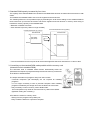
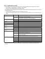
ADVANCED AND EVER ADVANCING
MITSUBISHI ELECTRIC
2000 No.135E
MITSUBISHI
NEW PRODUCT RELEASE
GENERAL-PURPOSE
PROGRAMMABLE LOGIC CONTROLLERS
Notification of the MELSEC-Q Series PLC CPU Upgrade
(Q02CPU,Q02HCPU,Q06HCPU,Q12HCPU,Q25HCPU)
New!
The following functions have been added to the QCPU to make it even easier to use.
The additional functions are shown as follows.
!Multiple PLC system compatibility
" Sequence control and motion control are incorporated in one PLC system.
" High-speed control by distributing load over multiple CPUs.
" Total volume of program memory and devices expanded by the addition of CPU modules.
" Operations of other CPU modules continue while one of the CPU modules goes down.
!Standard RAM capacity increased by four times
The capacity of the standard RAM in the Q12HCPU and Q25HCPU has been increased to 128k words to enable
the use of more file registers and local devices.
!Overwriting on the standard ROM made possible with the memory card
(Automatic write to standard ROM)
When ROM operations are being performed with the standard ROM, it is possible to write over the parameters
and programs in the standard ROM directly from a memory card at the field without PC (GX Developer).
!Debug on Line
(Forced ON/OFF of external inputs/outputs)
System debug with forcibly switch the I/O (X, Y) to ON/OFF by GX Developer is possible on Line.
!Possible to restrict access from external sources (Remote password setting)
It is possible to prevent QCPU from illegal remote access through serial communications or Ethernets.
!Compatible with MELSECNET/H remote I/O networks
1. Multiple PLC system compatibility
(1) Outline of multiple PLC system
Multiple PLC system is the system which enable a maximum of four QCPUs (PLC CPUs) or motion CPUs
(*1) mounted onto the main base unit to control the I/O modules and intelligent function modules.
In the multi PLC system, the CPU slots are assigned to PLC No. 1, No. 2, No. 3 and No. 4 in order from left to
right to specify the loaded QCPUs and motion CPUs.
QCPU1
QCPU2
Q25HCPU
Q61P-A1
Q25HCPU
QX10
QX10
QX41
QX41
QX10
QX10
*2
CPU slot:PLC No.1
Slot 0:PLC No.2
Slot 1:PLC No.3
Slot 2:PLC No.4
QX41
POWER
MODE
MODE
RUN
ERR
RUN
ERR
USER
BAT
USER
BAT
BOOT
BOOT
PULL
PULL
PULL
USB
USB
RS-232
RS-232
Q25HCPU
POWER
Q61P-A1
1 1
1 1
2
2 2
Setting of
controlling QCPU
Q25HCPU
MODE
Q25HCPU
MODE
Q25HCPU
MODE
QX10
QX10
MODE
RUN
ERR
USER
BAT
RUN
ERR
USER
BAT
RUN
ERR
USER
BAT
RUN
ERR
USER
BAT
BOOT
BOOT
BOOT
BOOT
PULL
PULL
PULL
Controlled by
sequence program
in QCPU1
PULL
PULL
USB
USB
USB
USB
RS-232
RS-232
RS-232
RS-232
Controlled by sequence program in QCPU2
*1: Motion CPUs are CPU modules that are connected to Mitsubishi servo amplifiers with SSCNET (which
reduces wiring and afford highly reliable connections) in order to perform motion control.
This enables synchronous operations with the servo motors and the simple structuring of absolute
position systems.
The motion CPUs will be released soon.
*2: The CPU slot (slot on the right of the power supply module) accepts only the QCPU.
(2) Features
(a) Possible to incorporate sequence control and motion control in one PLC system
It is possible to select the most suitable CPU module from the PLC CPUs (five types) and motion CPUs
(two types) in accordance with the size and use of the system when structuring systems.
PLC CPU
Sequence control
Q motion CPU
Q25HCPU
Q61P-A1
Q25HCPU
Q25HCPU
Q25HCPU
QX10
QX10
POWER
MODE
RUN
ERR
USER
BAT
MODE
RUN
ERR
USER
BAT
MODE
RUN
ERR
USER
BAT
MODE
RUN
ERR
USER
BAT
BOOT
BOOT
BOOT
BOOT
PULL
PULL
PULL
PULL
PULL
USB
USB
USB
USB
RS-232
RS-232
RS-232
RS-232
Motion control
Enables sequence control and
motion control in one system
(b) High-speed control by dispersing the load brought about by control tact
By separating and isolating CPU modules for each control item, such as machine control and data
processing, it is possible to enable high-speed control without affecting data processing or other
processes.
Q61P-A1
POWER
Q25HCPU
MODE
RUN
ERR
USER
BAT
QJ71BR11
RUN
T.PASS
SD
ERR
MNG
D.LINK
RD
ERR
QX10
QX10
(Several to several 10ms control)
Data processing CPU
(Less than 1ms control)
Machine controlling CPU
Data processing (slow)
Machine control (fast)
QX41
POWER
Q61P-A1
Q25HCPU
BOOT
PULL
Q25HCPU
QX10
MODE
RUN
ERR
USER
BAT
MODE
RUN
ERR
USER
BAT
BOOT
BOOT
QX10
QX41
QJ71BR11
RUN
T.PASS
SD
ERR
MNG
D.LINK
RD
ERR
PULL
PULL
PULL
PULL
USB
USB
USB
RS-232
RS-232
RS-232
Machine control is executed further faster
by load distribution according to control tact
All controls executed by single CPU
(c) CPU modules additions make it possible to expand the program memory and the number of devices
As it is not necessary to change I/O numbers when adding CPU modules, it is possible to expand
program memory and the number of devices without having to amend existing programs.
10% of the
memory available
Possible to expand by adding CPU modules
Q61P-A1
POW ER
Q25HCPU
MODE
RUN
QJ71BR11
RUN
T.PASS
SD
ER R
MNG
D.LIN K
RD
ER R
QX10
QX10
QX41
Q61P-A1
POW ER
Q25HCPU
Q25HCPU
MODE
MODE
RUN
RUN
ER R
ER R
ER R
USER
USER
USER
BA T
BA T
BA T
BOOT
BOOT
BOOT
PU LL
QJ71BR11
RUN
T.PASS
SD
ER R
MNG
D.LIN K
RD
ER R
QX10
QX10
QX41
PU LL
PU LL
90% of memory
in use
PU LL
PU LL
USB
USB
USB
RS-23 2
RS-23 2
RS-23 2
Addition of one CPU modules:
Expansion of program memory.
Expansion of device memory.
(d) Possible to continue operations with other CPU modules even when one CPU module goes down
As the operations (continue/stop) for other CPU modules can be set with parameters when one CPU
module goes down, it is possible to keep the damage to the entire system at a minimum when an error
occurs with one CPU module.
However, operations for PLC No.2 to 4 will be suspended if PLC No.1, which controls the multiple PLC
system, goes down.
Q6 1P-A1
POWER
Q25HCPU
QX10
QX10
QX10
QX10
QX10
QX10
QX10
QX10
QX10
Q6 1P-A1
POWER
Q25HCPU
MOD E
Q25HCPU
MOD E
R UN
Q25HCPU
MOD E
R UN
ER R
QX10
QX10
QX10
QX10
QX10
QX10
QX10
ER R
U SER
U SER
BA T
BA T
BA T
BA T
BOOT
BOOT
BOOT
PU LL
QX10
R UN
ER R
U SER
QX10
MOD E
R UN
ER R
U SER
BOOT
PU LL
PU LL
PU LL
PU LL
PU LL
U SB
U SB
U SB
U SB
R S-232
R S-232
R S-232
R S-232
If one CPU module goes down,
the entire system goes down
Possible to continue operations with other CPU
modules even when one CPU module goes down
2. Standard RAM capacity increased by four times
The capacity of the standard RAM in the Q12HCPU and Q25HCPU has been increased from 32k words to 128k
words.
This enables the standard RAM to use more file registers and local devices.
The following effects are now possible simply by amending the local device settings in the standard RAM for
those users who up until now have had to set the file registers and local devices in memory cards owing to
insufficient memory capacity in the standard RAM.
" Reduction of QCPU scan time *
" Cost reductions (memory cards no longer needed)
Q12HCPU/Q25HCPU after upgrading
Q12HCPU/Q25HCPU up until now
Standard
RAM
u ƒ ƒ
ƒ
b ƒ
N 1
Standard RAM
u ƒ ƒ
ƒ
b ƒ
N 1
R0
t @
ƒ
ƒ ƒ
C ƒ
‹ ƒ
Œ ƒ
W X
ƒ ^ƒ
Increased by
four times
ZR0
t @
ƒ
ƒ ƒ
C ƒ
‹ ƒ
Œ ƒ
W X
ƒ ^ƒ
i 32k“_ j
i 32k“_ j
to File register
(32k points)
R32767
File register
to (128k points)
ZR131071
*: The remove/restore time for 4k point local devices with eight files has been reduced from 31.5ms to 6ms.
3. Overwriting on the standard ROM made possible with the memory card
(Automatic write to standard ROM)
The automatic write to standard ROM function automatically writes the
parameters and sequence programs already stored in the memory card across
to the QCPU's standard ROM.
The simple amendment of programs away from the local site.
" Personal computers (GX Developer) are not required for installing
programs.
It is no longer necessary to take a personal computer when installing
programs amended by the design office into the QCPU at a local sites.
" Only necessary to send a memory card to distant sites.
The local operator only needs to insert the memory card into the QCPU.
(Dipswitch setting are necessary.)
ATA cards are useful for memory cards.
" Saving from the program lost by battery out.
" Easy to load the data from a personal computer.
Program
file
Parameter
file
Memory card
Local site
CPU
Program
memory
Standard ROM
4. Possible to debug the QCPU during operations (Forced ON/OFF of external inputs/outputs)
The forced ON/OFF of external inputs/outputs is a function that enables the GX Developer to forcibly switch the
input (X) and output (Y) ON and OFF while the QCPU is operating.
<In the case of PLC test functions>
Not possible to switch off with PLC tests
X0
Sensor input ON
X0
M100
ON
Sensor input
Y10
M0
Facility abnormality
detection ON
Facility warning alarm output
ON OFF
Y10
Warning alarm
output
Not possible to switch ON and
OFF with the PLC test while
the QCPU is operating
<In the case of forced ON/OFF of external input>
OFF possible with enforced input
X0
M100
OFF
Sensor input
Personal
computer
(GX Developer)
ON and OFFof external output
possible with enforced output
M0
Facility abnormality
detection ON
Y10
Warning alarm
output
Note: Y10 is set at OFF in the output module,
but remains ON with the circuit.
[Forced ON/OFF of external input]
The enforced OFF function can set the system at OFF without disconnecting the external lines when the
sensor remains ON.
[Forced ON/OFF of external output]
By forcibly setting the warning alarm output signal for other facilities to OFF when it remains on during
facility start-up, it is possible to resolve the system error and continue with test operations.
5. Possible to restrict access from external sources (Remote password setting)
(1) The remote password prevents remote users from illegally accessing the QCPU from remote locations (the
remote passwords restricts the writing of parameters, sequence programs and device data.)
The remote password set will be written into the QCPU as a parameter.
[During access via public telephone lines]
[During access via Ethernets]
Modem
Public
telephone line
Accessing
machine
Accessing
machine
(Host station)
Modem
Ethernet
(2) Remote passwords are made possible through combinations of the following modules.
" Serial communication modules of function version B (QJ71C24 (-R2))
" Ethernet modules of function version B (QJ71E71 (-B2))
6. Compatible with MELSECNET/H remote I/O networks
(1) It is compatible with a remote I/O system with the use of Q series I/O.
MELSECNET/H remote I/O network
(2) The MELSECNET/H module (QJ71LP21-25, QJ71BR11) of function version B is necessary to structure a
MELSECNET/H remote I/O network.
[Compatible CPU]
Function
Relevant QCPU
Multiple PLC system compatibility
Increased standard RAM capacity
(Q12HCPU and Q25HCPU only)
Automatic writing in the standard ROM
Forced ON/OFF of external inputs/outputs
Remote password setting
MELSECNET/H remote I/O network compatible
Relevant GX Developer
" QCPUs with function version B or higher Version 6
(products shipped during and after (SW6D5C-GPPW) or
higher
November 2000)
" QCPUs with function version B or higher.
" QCPUs with serial numbers of 02092 or
higher (products shipped during and after
September 2000)
[Verifying the serial numbers and function versions]
The serial number and function version can be verified from the SERIAL column on the QCPU name plate. The
serial numbers and function versions can also be verified for GX Developers.
SERIAL 02092
-B
Serial number
(first five digits)
Function version
[List of configurable functions]
The MELSEC-Q series modules listed below can be used without modification for multiple PLC systems.
" Input modules, output modules, I/O modules, power modules
" Basic base units, additional base units, addition cables
The intelligent function modules that are restricted for use with multiple PLC systems depending on the function
version are listed below.
" Function version A modules can only be controlled with PLC No.1.
" The modules used with PLC No. 2 to 4 of a multiple PLC system should be those of function version B or
later.
Product
MELSECNET/H module
Type
QJ71BR11
QJ71LP21-25
Ethernet module
Serial communication
module
CC-Link module
FL-net module
Intelligent communication
module
Analog/digital conversion
module
Digital/analog conversion
module
Temperature control module
QJ71E71
QJ71E71-B2
QJ71C24
QJ71C24-R2
QJ61BT11
QJ71FL71
QD51
QD51-R24
Q64AD
Q68ADV
Q68ADI
Q62DA
Q64DA
Q64TCTT
Q64TCTTBW
Q64TCRT
Q64TCRTBW
Positioning module
QD75P1
QD75P2
QD75P4
QD75D1
QD75D2
QD75D4
Description
10Mbps communication speed-compatible coaxial bus (control station,
normal station, remote master station)
10Mbps/25Mbps communication speed-compatible duplex optical bus
(control station, normal station, remote master station)
Ethernet interface module (10BASE-T, 10BASE5)
Ethernet interface module (10BASE2)
RS-232, RS-422/485, 1 channel each
RS-232, 2 channels
Master station, local station
FL-net (OPCN-2) interface module
BASIC program, 2 channels of RS232C
BASIC program, 1 channel of RS232C, 1 channel of RS-422
Analog input (voltage, current), 4 channels
Analog input (voltage), 8 channels
Analog input (current), 8 channels
Analog output, 2 channels (voltage, current)
Analog output, 4 channels (voltage, current)
Temperature control module, thermocouple input, transistor output
Temperature control module with disconnection detection function
Thermocouple input, transistor output
Temperature control module, platinum temperature-measuring resistor
input, transistor output
Temperature control module with disconnection detection function
Platinum temperature-measuring resistor input, transistor output
Pulse train open collector output, 1 axis
Pulse train open collector output, 2 axes
Pulse train open collector output, 4 axes
Pulse train differential output, 1 axis
Pulse train differential output, 2 axes
Pulse train differential output, 4 axes
Refer to the data book for details on the possibility of using AnS series I/O modules and special function
modules.
[Manuals]
Manual name
QCPU(Q mode) User’s Manual
(Functions Explanation/Proguram Fundamentals)
QCPU(QMode)/QnACPU Programming Manual
(Common Instructions)
Country/Region
U.S.A
Brazil
Germany
U.K
Italy
Spain
South Africa
Hong Kong
China
Taiwan
Korea
Singapore
Thailand
Indonesia
India
Australia
Manual shipment type
IB/SH No.
Type code
Sold separately
SH-0080038-B
13JL98
Sold separately
SH-0080039-C
13JF58
Sales office
Mitsubishi Electric Automation Inc.
500 Corporate Woods Parkway Vernon Hills, IL 60061
MELCO-TEC Rep. Com.e Assessoria Tecnica Ltda.
Av. Rio Branco, 123-15 ,and S/1507, Rio de Janeiro, RJ CEP 20040-005, Brazil
Mitsubishi Electric Europe B.V. German Branch
Gothaer Strasse 8 D-40880 Ratingen, GERMANY
Mitsubishi Electric Europe B.V. UK Branch
Travellers Lane, Hatfield, Herts., AL10 8XB,UK
Mitsubishi Electric Europe B.V. Italian Branch
Centro Dir. Colleoni, Pal. Perseo - Ingr.2
Via Paracelso 12, 20041 Agrate B., Milano, Italy
Mitsubishi Electric Europe B.V. Spanish Branch
Pol. Ind. "Can Magi"- C/.Joan Buscalla, 2-4-A.C.420
08190 Sant Cugat del Valles, Barcelona, Spain
MSA Manufacturing (Pty) Ltd.
P O Box 39733 Bramley 201 8 Johannesburg, South Africa
Ryoden International Ltd.
10th Floor, Manulife Tower, 169 Electric Road, North Point, HongKong
Ryoden International Shanghai Ltd.
3F Block5 Building Automation Instrumentation Plaza 103 Cao Bao Rd. Shanghai
200233 China
Setsuyo Enterprise Co., Ltd.
6F., No.105 Wu-Kung 3rd.RD, Wu-Ku Hsiang, Taipei Hsine, Taiwan R.O.C.
HAN NEUNG TECHNO CO.,LTD.
1F Dong Seo Game Channel Bldg., 660-11,Deungchon-dong Kangsec-ku,
Seoul, Korea
Mitsubishi Electric Asia Pte, Ltd.
307 ALEXANDRA ROAD #05-01/02,
MITSUBISHI ELECTRIC BUILDING SINGAPORE 159943
F. A. Tech Co.,Ltd.
898/28,29,30 S.V.CITY BUILDING,OFFICE TOWER 2,FLOOR
17-18 RAMA 3 ROAD,BANGKPONGPANG,YANNAWA,BANGKOK 10120
P.T. Autoteknindo SUMBER MAKMUR
JL. MUARA KARANG SELATAN BLOK A UTARA NO.1 KAV.
NO.11 KAWASAN INDUSTRI/ PERGUDANGAN JAKARTA - UTARA 14440
Messung Systems Put,Ltd.
Electronic Sadan NO:111 Unit No15, M.I.D.C BHOSARI,PUNE-411026
Mitsubishi Electric Australia Pty. Ltd.
348 Victoria Road, PostalBag, No 2, Rydalmere, N.S.W 2116, Australia
Tel/Fax
Tel : 1-847-478-2100
Fax : 1-847-478-0328
Tel : 55-21-221-8343
Fax : 55-21-221-9388
Tel : 49-2102-486-0
Fax : 49-2102-486-717
Tel : 44-1707-276100
Fax : 44-1707-278695
Tel : 39-039-6053301
Fax : 39-039-6053312
Tel : 34-935-653135
Fax : 34-935-891579
Tel
Fax
Tel
Fax
Tel
Fax
: 27-11-444-8080
: 27-11-444-8304
: 852-2887-8870
: 852-2887-7984
: 86-21-6475-3228
: 86-21-6484-6996
Tel
Fax
Tel
Fax
: 886-2-2299-2499
: 886-2-2299-2509
: 82-2-3668-6567
: 82-2-3664-8335
Tel : 65-473-2480
Fax : 65-476-7439
Tel : 66-2-682-6522
Fax : 66-2-682-6020
Tel : 62-21-663-0833
Fax : 62-21-663-0832
Tel
Fax
Tel
Fax
: 91-20-7128927
: 91-20-7128108
: 61-2-9684-7777
: 61-2-9684-7245
HEAD OFFICE:MITSUBISHI DENKI BLDG MARUNOUCHI TOKYO 100-8310 TELEX:J24532 CABLE MELCO TOKYO
00 (MEE)
Specifications subject to change without notice.
Printed in Japan on recycled paper.