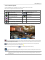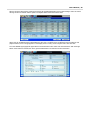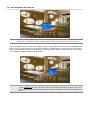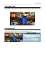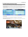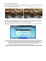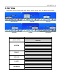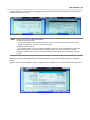
1
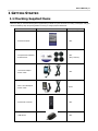
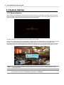
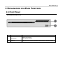
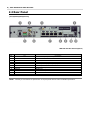
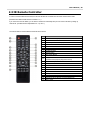
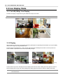
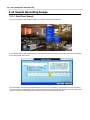
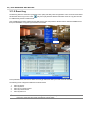
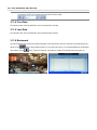
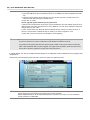
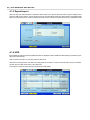
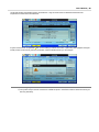
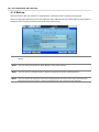
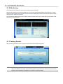
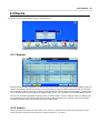
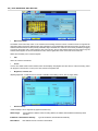
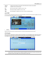
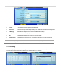
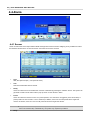
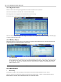
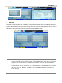
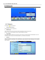
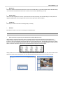
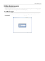
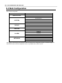
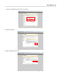
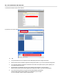
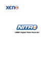
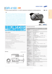
1 | FULL HD Network Video Recorder Safety Information The safety information is provided for the wellness of the equipment and for the safety of the operator. Please review and observe all instructions and warnings in this manual. Note : Keep this manual handy every time you operate this equipment. Also, check with your dealer for further assistance and for the latest revision of this manual. Your dealer might provide you with a digital version of this manual. We also ask to keep the original box and packing materials in case of return and for long-term storage of the NVR unit. Preparations before installation To protect your NVR from damage and to optimize performance, be sure to keep the NVR away from dust, humidity, and area with high voltage equipment such as refrigerator. Do not install or place equipment in areas where the air vents can be obstructed, such as in tight enclosures or small utility closet. Keeping the unit in a temperature-controlled room with ample regulated power is highly recommended. Do not overload the wall outlet, as this can result in the risk of fire or electric shock. Uninterruptible power devices such as UPS power surge protectors are recommended, and the NVR units must at least be connected with UL, CUL, or CSA approved power surge protector. Avoid direct sun light and avoid heat. FCC Information This equipment has been tested and found to comply with the limits of Class A digital device, pursuant to part 15 of the FCC Rules. These limits are designed to provide reasonable protection against harmful interference when the equipment is operated in a commercial environment. This equipment generates, uses, and radiates radio frequency energy, and if not installed and used in accordance with the instruction manual, may cause harmful interference to radio communications. Operation of this equipment in a residential area is likely to cause harmful interference in which case the user will be required to correct the interference at his own expense. Changes or modifications not expressly approved by the party responsible for compliance could void the user's authority to operate the equipment under FCC rules. UL Information - for pluggable equipment, the socket-outlet shall be installed near the equipment and shall be easily accessible - if the battery is placed elsewhere in the equipment, there shall be a marking close to the battery or statement in the servicing instructions. CAUTION RISK OF EXPLOSION IF AN INCORRECT TYPE REPLACES BATTERY. DISPOSE OF USED BATTERIES ACCORDING TO THE INSTRUCTION. THIS EQUIPMENT IS FOR INDOOR USE, AND ALL THE COMMUNICATION WIRING IS LIMITED TO INSIDE OF THE BUILDING, OR ANY SIMILAR WORD. User’s Manual | 2 Contents CHAPTER 1 : NVR USER MANUAL 1 GETTING STARTED 6 1.1 Checking Supplied Items 6 1.2 System Startup 7 2 EXPLANATION FOR EACH FUNCTION 2.1 Front Panel 2.2 Rear Panel 2.3 IR Remote Controller 3 OPERATION 8 8 9 10 11 3.1 User Log-in 11 3.2 Quick Setup 12 3.3 Live Display Mode 13 3.4 PTZ Operation 18 3.5 Freeze Mode 20 3.6 Registration 20 3.7 Instant Record 21 3.8 Playback of Recorded Video 22 3.9 Simultaneous Live and Playback (CAMEO) 23 3.10 Quick Backup during Live & Playback 24 3.11 Search Recording Image 25 3.12 DST Setting and Screen Saver 30 4 SETTING 32 4.1 System 33 4.2 Device 42 4.3 Record 45 4.4 Alarm 47 4.5 Network 51 5 WEB SURVEILLANCE 56 5.1 Web Login 56 5.2 Web Configuration 57 5.3 Web monitoring 59 5.4 Web Playback 62 3 | FULL HD Network Video Recorder 6 APPENDIX : DYNDNS SITE REGISTRATION 63 7 APPENDIX : SPECIFICATION 66 User’s Manual | 4 Chapter 1 NVR USER MANUAL 5 | FULL HD Network Video Recorder User’s Manual | 6 1 GETTING STARTED 1.1 Checking Supplied Items Make sure that you have the following items supplied with your NVR. If any of these items are missing or damaged, notify your vendor immediately. Keep the packing utilities for moving or storage purposes afterwards. Items Photo Quantity Quick Start Guide 1 Set CD (Manual & Software) Rubber Mount 1 Set 1 Set (4 Pieces) 12V 3A DC Adaptor Power Cable 1 Set 48V 1.4A PoE Adaptor Power Cable Option IR Remote Controller 1 Set USB Mouse 1 Set 7 | FULL HD Network Video Recorder 1.2 System Startup 1.2.1 System Startup After connecting peripheral devices such as cameras, monitors and a mouse to the NVR, power up the NVR by connecting DC12V 3A adaptor to the power jack on the rear panel. The boot logo will display as shown below. Please wait until the boot process completes. Optional PoE needs independent power input of 48VDC. Login with ‘User Name’ at the login window which will appear as shown below. There is only one Administrator Account configurable in the NVR system. It is assigned with an unchangeable User ID marked as ‘admin’. The default password is empty (No Password). Administrator account has full access to the NVR and its configurable parameters. The Administrator Account also has the ability to create new users and to assign rights to the new user accounts. Those new users created by ‘admin’ account can also login with a specific password set by ‘admin’ account. NOTE Do not forget the administrator’s password that was set for the first time. In case the password is lost, contact your vendor. NOTE The mouse is included. In case you need to replace it, it is highly recommended to choose well-known major brands such as DELL, MICROSOFT, LOGITECH, or SAMSUNG. User’s Manual | 8 2 EXPLANATION FOR EACH FUNCTION 2.1 Front Panel [4CH (W)280x(H)48x(D)273mm] No. Items Functions 1 LED Indicator Indicate System Status Power, Record, Network 2 USB Port USB Port (Ver. 2.0) for Mouse Operation, Backup Device or Firmware Update 9 | FULL HD Network Video Recorder 2.2 Rear Panel [4CH (W)280x(H)48x(D)273mm] *INR-4CH with Wi-Fi Antenna(Option) No. 1 2 PoE Power Audio IN/OUT PoE Power Input (48V/1.4A) Audio In/Out Port 4 5 6 7 8 9 10 11 ON/OFF ALARM IN/OUT USB PoE Ethernet HDMI e-SATA DC12V Power ON/OFF Switch Alarm Input/Output (1Relay output) Mouse Input PoE Camera Input WAN Port True HDMI Output e-SATA Main Power Input (12V/3A) NOTE I/O Functions Carefully check whether the specification of the peripheral devices match the NVR’s specification. User’s Manual | 10 2.3 IR Remote Controller In order to use the IR Remote Controller, the ID of the IR Remote Controller must be same as the ID of the NVR. (Default ID # for NVR and IR Remote Controller is “1”.) If you have more than two NVRs, you are able to control them individually with just one remote controller by setting up ‘Remote ID’. (The Remote ID is adjustable from ‘1’ up to ‘8’.) The function buttons of the IR Remote Controller are as below. No. Functions 1 Start Instant Emergency Record 2 Numeric Buttons 3 Auto-Sequence on Live Display Mode 4 Freeze Button to Pause Live Video 5 Call Monitor Activation 6 Channel Selection 7 Instant Playback 8 Search Button 9 OK (Select) Button 10 Audio Mute 11 Playback Control on Search Mode (Fast Backward/Playback/Stop/Fast Forward) 12 Exit Menu Setup 13 Display Mode 14 Zoom 15 PIP Mode 16 Bookmark 17 Zoom In & Out Button 18 Backup 19 PTZ Control 20 Directional Arrows Buttons (Up/Down/Right/Left) 21 Menu Setup 11 | FULL HD Network Video Recorder 3 OPERATION 3.1 User Log-in Check the power connection. The system can be used after power-on. The NVR has various setting categories. The administrator can set the system password and <User> to prevent unauthorized changes to setting values and alteration of recorded file. Enter the <Admin> or <User> password which has been set by using the virtual keyboard. NOTE 1) <LOGIN> window will be permanently displayed in monitor as above picture until user logs in with the right ID and password. The default user ID is ‘admin’ and password is none(No password). 2) If it is set as Auto Log-In, NVR does not require LOG-IN. (Please refer to 4.1.2 User.) 3) Please be sure that the PoE Adapter should be connected to the NVR after the NVR is turned on so that the IP address can be allocated properly to NVR. The “HELP” button will help you understand how to setup several important settings, even without the user’s manual book. For example, if you need help about how to set “Quick Setup”, click “HELP” button at the right bottom of the ‘Quick Setup’ menu. User’s Manual | 12 3.2 Quick Setup 3.2.1 NVR Setup Quick Setup is specially designed to enable easier & faster configuration for the major NVR settings such as NVR network setup, IP camera search & registration. When the NVR boots up, the Quick Setup will be operated automatically after logging in. The Quick Setup pop-up is controllerable in the main menu. There are two ways for connecting to network setup: DHCP or Static IP. The fatory default setting is as followings: [WAN Port] IP Address: 192.168.1.160 Subnet Mask: 255.255.255.0 Gateway: 192.168.1.1 [Local Port: Switch Setting] IP Address: 10.10.1.1 Subnet Mask: 255.255.255.0 Gateway: 10.10.1.1 3.2.2 IP Camera Connection When the IP cameras are connected to the NVR, the user can search the connected cameras by clicking the ‘Search’ button. Once the cameras are searched, check the box of each camera and click the ‘Add to Camera List’ button. Then the cameras will be shown in the list at the bottom. Click ‘Save’ button. NOTE In case of requiring the ID and Password for certain IP cameras for proper registration, please click the ‘Edit’ button. The ID and Password should be the one which are used for web configuration page. 13 | FULL HD Network Video Recorder 3.3 Live Display Mode 3.3.1 Full HD(1080p) Live Display Full HD Live Display is supported using the HDMI video output of the NVR. NOTE In playback mode, the maximum resolution is 1920*1080(main) and 640*360(secondary) <Full HD Live & Playback Display> 3.3.2 Display Channel selection can be done on the remote controller by pressing the corresponding channel buttons (1,2,3,4) and display mode can be changed by using the MODE button. The live images can be displayed in 1 and 4 channel mode. Whenever the left/right arrow button on the front panel or IR remote controller is pressed, the screen will be sequentially changed. [1 Ch] [4 Ch] To select channel by mouse, click target channel to display in full screen live mode. Clicking the screen again is to return to previous display mode. Pop-up menu will be displayed by clicking right mouse button to select the display mode easily. NOTE To properly select a channel using the mouse, the user is required to perform a slow and clear click of the left mouse button. User’s Manual | 14 3.3.3 Icons Description The live mode displays icons or messages on the screen to indicate the system mode or status. Below are the icon categories that are indicated on the monitor. Icon to be shown at Left-upper corner on each channel screen Icon to be shown at Left-bottom corner on full screen. Continuous Recording Sequence display on Motion Detection Recording Digital zoom on Sensor Activating Recording Audio Channel Motion Detection + Sensor Activating Recording Instant Recording (Emergency Rec) Continuous Recording + Motion Recording The sliding menu for display will appear when the mouse cursor is moved to the bottom of the display and right clicking the mouse enables to a pop-up for menu access. means “Instant (emergency) recording”, which is useful to urgently start recording. In emergency recording, the system follows the instant record settings. The default settings for instant record are maximum performance recording of streaming from IP camera and applied for all channels. means “PTZ” mode, which is useful to instantly switch to PTZ control. In PTZ mode, user can move pan/tilt and zoom-in/out by moving the mouse pointer, like a virtual joystick. User can click the right-forwarded arrow button to automatically playback the latest video clip. means the HDD usage percentage by video recording. If it shows 60%, then 60% of HDD space has been used up for recording. NOTE If you cannot find any colored-mark in the top right corner of the live screen mode, then it means that the system does not record any image. In this case, you need to check recording schedule or camera of the main setup menu. 15 | FULL HD Network Video Recorder 3.3.4 Pop-up Menu User can click the right button of the mouse to pop up a sub-menu as shown below. When “SEQUENCE” is selected, sequentially changed. icon is shown on the bottom left corner of the screen, and display screen will be User can select the “ZOOM” on a sub-menu by clicking the right mouse button on a full screen mode. When digital zoom function is activated, icon will be shown and zoomed area will be displayed on the bottom left corner. User can select “Zoom-In size(x1.5, x2, x2.5 or x3)” on zoom pop-up menu. After selecting, move a yellow box by using the mouse to drag in the desired area of the camera to zoom. In order to go back to live display mode, please click “Zoom-In size” again. User’s Manual | 16 When a camera is disconnected, a warning sound may be generated depending on the system settings. Users can set the warning sound from ‘Network Failure’ option in the System Alarm section of the Alarm menu. Admin user can set different level of authorization for each user. If a certain user is not allowed to view a certain live and playback channel, then no image appears on the display screen. To setup, move to System menu and click ‘User’. The ‘User Add/Edit’ popup page will appear like the screenshot below when admin user clicks the button ‘Add’ at the right bottom. If the boxes are checked, the user is granted authorization to access each function and section. 17 | FULL HD Network Video Recorder 3.3.5 Switch Stream The NVR can perform dual recording from dual stream supported network cameras. The user can select a desired stream by network condition during Live and Playback mode. NOTE Switch Stream function will only be available for 8CH and 16CH NVR. 3.3.6 Alarm Status Intuitively, System alarm and Camera alarm will be displayed in icons. System alarm includes HDD S.M.A.R.T, Fan failure, Disk Error and No Disk and Recording failure. Camera alarm displays network connection status, motion event and sensor event from connected cameras. However, motion and sensor from camera will only be displayed when a network camera supports the motion and sensor. [Alarm Deactivated] [Alarm Activated] User’s Manual | 18 3.4 PTZ Operation The PTZ menu will only be available when a PTZ camera is connected to NVR. The user can go to PTZ mode by right clicking the mouse and selecting “PTZ” in the pop-up menu as shown below or by selecting the joystick button in the menu bar located on the bottom of the main screen. The PTZ mode will only be activated while in full screen when a PTZ camera is connected. In PTZ mode, the user can control the PTZ operations with a USB mouse. While pressing the left button of the mouse, the user can drag the mouse pointer up/down or left/right to move the pan/tilt position of the camera. If the user moves the mouse pointer far away from the center position of the main screen, the PTZ camera will increase its pan/tilt speed. The user can also zoom-in/out by rolling the wheel of mouse up or down. NOTE PTZ functions are available by using the USB mouse and the IR remote control. For focus control in PTZ screen mode, the user can right click the mouse to get the pop-up menu as shown below. The default mode is to “ZOOM”. The user can select “FOCUS” to switch the wheel function of mouse from zoom-in/out to focus. This will change the default behavior of the mouse wheel. The user can also select the preset button or exit PTZ screen mode. 19 | FULL HD Network Video Recorder NOTE User will see numeric pad to select “Preset” number. The preset is defined by setting a PTZ protocol in the setting menu. The maximum number of preset is 255, but the max supported by the PTZ may be less. User can automatically switch the PTZ camera positions according to the predefined preset settings by using GUARD TOUR function. The connected PTZ camera must support touring functions. “GUARD TOUR” on the pop-up menu can be enabled after the channel that the PTZ camera is connected to is changed to full screen. Please make sure that PTZ camera setting is correct, otherwise, “GUARD TOUR” is shown as disabled. CAUTION Depending on PTZ camera, some preset positions might be skipped if, for example, the PTZ camera cannot mechanically move or control focus within the interval time required by the NVR. In this case, it is recommended to increase the interval setting to a value that allows for the cameras to finish its Pan & Tilt. User’s Manual | 20 3.5 Freeze Mode Click the right button on the mouse and select the Freeze mode while viewing a live image. In the Freeze mode, the image pauses; the date/ time information does not; and the system clock continues running. Press FREEZE to pause the live view. To resume the live view, press FREEZE again, or click the right button on the mouse and select the FREEZE again. 3.6 Registration When the user wants to change the camera source, the registration menu allows the NVR to search and register connected network cameras easily. Click the right button on the mouse and select ‘Registration’ to move. 21 | FULL HD Network Video Recorder 3.7 Instant Record In the case of emergency, the user can enable the Instant Record feature. Click the right button on the mouse and select ‘Instant Record’ and the icon will be appeared and changed to Red ( ) After clicking ‘Instant Rec’, the icon will be changed as seen in the picture below. Click ‘Instant Rec’ once again to escape. User’s Manual | 22 3.8 Playback of Recorded Video It is easy to use the USB mouse to playback recorded files. The recorded files can be seen backwards or forwards. Press the rewind and fast-forward buttons, and the playback speed can be controlled in steps of 2, 4, 8, 16, and 32 times real time when playing backwards( ) or forwards( ). Users can also play ‘Frame by Frame’ by clicking the button or . Please be aware that playing frame by frame in reverse will only display the I-frame (First recorded image for every second of video). While viewing the live camera feed, the playback button also be performed by using the pop-up menu. can be used to automatically play the latest video clip. This can The picture below shows the system playing back a video. In the playback screen, the user has various playback options such as; make an instant manual backup (archive), go to calendar search mode, change channel, and change screen modes. By clicking the left mouse button in the colored-time bar, the user can jump to a different time in the recording. In addition, the vertical bar on the time bar can be dragged (hold left click) to quickly advance or reverse time while still displaying the related recorded video. Once at the desired position, release left click to begin your normal playback mode from that time. 23 | FULL HD Network Video Recorder 3.9 Simultaneous Live and Playback (CAMEO) The Cameo function allows viewing playback of a single channel, while viewing the live camera display simultaneously on other channels. In live view mode, right click the mouse on the channel that is desired to playback and then select Cameo to activate this function. Users can see the blue frame on the CH1 screen when Cameo function is activated as shown below. User’s Manual | 24 3.10 Quick Backup during Live & Playback Video can be easily archived while viewing during live and playback mode. In live & playback mode, the user can right click the mouse and the Backup menu will appear immediately. When desired playback period is decided, set the start time and end time with target channels. After plugging the USB stick into the NVR, left click “Scan” to allow the NVR to find the flash drive. After the USB flash drive is detected, enter a file name in the field below. A password and backup viewer can also be added to the backup for security and ease of use. 25 | FULL HD Network Video Recorder 3.11 Search Recording Image 3.11.1 Date/Time Search The user can select the date and time to search for a certain file within the recorded video. In the calendar, dates in RED means that there is recorded video data. Click a desired date in Red. Then, the recorded data for the selected date will be shown. Once the recorded video data of the selected date is shown, the user can adjust the vertical search line to the time that the user wants to search by dragging the mouse. As the vertical line is moved back and forth, the user can see the “Search time” clock also changes. Once the search time is decided, click Play to see the selected video data. User’s Manual | 26 The colors of the time bar are different, depending on the recording mode. No color - NONE “NONE” means there is no recorded video for that time slot. Red color - Instant recording Yellow color - Continuous recording Green color - Motion-detection recording In this mode, the system records only when motion is detected The motion-recording configuration can be set in the camera menu from the NVR directly, or from the network camera configuration. Orange color - Sensor-activated recording In sensor mode, the system will record when a sensor is triggered during the dwell time as set in “SENSOR” of the “ALARM” menu. Sensor input can be selected between camera input sensor and NVR input sensor. NVR input sensor is a direct alarm input to the NVR physically and a Camera input sensor is triggered by network. The user should verify if the specific network camera is integrated with the NVR to the manufacturer. Pink color - Motion detection + Sensor-activated recording The system does not record without motion and sensor event. Motion event data comes from the network camera and can be set in “Camera” in “DEVICE” menu. This menu is for integrated network camera settings and sensor type need to included in “Sensor” in “ALARM” menu. If user sets “OFF” in both “MOTION” and “SENSOR” in the “DEVICE” menu, then the system will neither record nor notify the Advanced Client Software or Central Management System. Light Blue color - Continuous + Motion recording In this mode, the system records with the continuous recording mode settings when no motion is detected. However, if motion is detected, the system will start recording with the motion recording mode settings. During continuous recording mode, the system records with 1 frame per second. When motion recording mode is activated, the system will follow the camera setting value which the user can set in the record setup menu. *Record Setup is available only for approved camera models. 27 | FULL HD Network Video Recorder 3.11.2 Event Log The Event log search is used to find a particular event, quickly and easily. Click the right button on the mouse as shown below and select the ‘Event Log’ to move. Click to a USB memory device in text file format. play icon to play back the selected event data. Users can copy this event list Once a USB memory stick is inserted into the USB port, the user must press the “SCAN” button to detect the USB stick and then press “EXPORT” to copy the log information to the media. To sort particular events, the user can select an event type with time & date by a mouse or remote controller. The following are the categories indicated on the Event Viewer. 1. 2. 3. 4. 5. Alarm by Sensor Alarm by Motion Alarm by Connection Failure Alarm by Instant Record Alarm by HDD Full NOTE If the Alarm does not activate even though the alarm input setting has been made, check the alarm connection of the NVR rear panel and Network camera alarm. User’s Manual | 28 3.11.3 System Log The system log search can be used to find particular system log information, quickly and easily. The user can copy this event list to a USB memory device in text file format. Click the right button on the mouse as shown below and select the ‘System Log’ to move. Once export is completed, the user can find a date folder created in USB thumb drive. There is “system.log” file stored in the date folder. The following are the categories indicated on the system log viewer. 1. 2. 3. Log by system Log by setup Log by network 29 | FULL HD Network Video Recorder NOTE 20 numbers of log record will be shown on one page of the <System Log> and <Event Log> window. User can click the arrow icon to search the log records on another page. 3.11.4 First Data Go to the first screen of the recorded video. This is the oldest video recorded. 3.11.5 Last Data Go to the last screen of the recorded video. This is the latest video recorded. 3.11.6 Bookmark Go to the bookmark list to search the recorded video data in the bookmark list. Users can make their own bookmark list very simply by click video data by clicking button, during playback. When you do a bookmark search, you can easily playback the bookmarked button, right next to each list. The maximum number of bookmarks that can be kept is 32. User’s Manual | 30 3.12 DST Setting and Screen Saver DST starts at 2:00 local time on 2nd Sunday of March, and ends at 2:00 DST on 1st Sunday of November. During DST (Daylight Saving Time) period, the NVR time clock has to be adjusted according to the regional time zone. That is, the NVR time clock will be shifted by one hour after the DST settings start, and the NVR will restore the time clock back to normal after DST finishes. To enable the DST setting on the NVR, go to the menu: SYSTEM > SYSTEM INFO and click “DATE/TIME” to get the DST setting window as shown below. Users can setup DST “Begin & End” time after checking “USE DST” box. Since the clock jumps from 2:00 to 3:00, when you go to search mode, you can clearly see there is no data in all channels for one hour due to DST. DST ends at 2:00 DST, and the clock jumps backward to 1:00 standard time on 1st Sunday of November. When DST finishes, there is an hour of overlapped video. The overlapped time video will be indicated in a blue color in the Intelli-Search Bar during playback mode. 31 | FULL HD Network Video Recorder When the user clicks on such overlapped period, a message titled “Recorded video Selection” will pop up. The user can then select whether to play DST data or Non-DST data. Click OK to play DST image. [“DST” image is displayed on screen] Click CANCEL to play Non-DST image. [“Non-DST” image is displayed on screen] To enable the SCREEN SAVER setting on the NVR, go to the menu setup: SYSTEM > SYSTEM INFO and click “SCREEN SAVER” to get the SCREEN SAVER setting window as shown below. Users can select CRT and/or VGA by checking the boxes. Users can set the WAITING TIME for when the monitor will automatically turn off. Users can turn on the selected monitor by clicking a mouse, pressing any frontal key buttons, or pressing any buttons on the remote controller. NOTE WAITING TIME: Users can select the WAITING TIME from NONE, 1,2,3,4,5,6,7,8,9,10,20,30,40,50, and up to 60 MIN. The SCREEN SAVER will not work when either WAITING TIME is set to “NONE” or both SPOT and VGA checkbox are unchecked. SCREEN SAVER may not work during system upgrade, HDD format, or data backup process. The system continues to record while the monitor is turned off. When it comes to the “AUTO LOGOFF” setting, please refer to the USER setting. User’s Manual | 32 4 SETTING General setting structure consists of “Quick Setup”, “System”, “Device”, “Record”, “Alarm,” and ‘Network” as shown below. <QUICK SETUP> <RECORD> Main MENU QUICK SETUP SYSTEM DEVICE RECORD ALARM NETWORK <SYSTEM> <DEVICE> <ALARM> <NETWORK > Sub MENU NVR REGISTER SYSTEM INFO USER EXPORT/IMPORT HDD BACKUP MONITORING FACTORY DEFAULT REGISTER CAMERA PTZ AUDIO SCHEDULE RECORD SETUP HOLIDAY SENSOR SYSTEM ALARM MOTION ALARM NOTIFICATION NETWORK DDNS IP FILTER 33 | FULL HD Network Video Recorder 4.1 System The system menu button is selected by clicking the right mouse button. Users can address the mouse pointer for the “System” menu icon, sub-menu window will be displayed and user can move into specific menu by selection of sub-menu to set up and/or edit. 4.1.1 System Info Use this sub-menu to check system information status or to change the system-related configuration. Users can then move to other sub-menu of the System; System Info, User, Export/Import, HDD, backup, monitoring and Factory Default by moving mouse pointer or pressing the arrow buttons on the front panel. Mac address is a unique network identification number for each system. User’s Manual | 34 In “DATE/TIME SET,” user can activate DST (Daylight Saving Time). Select the time synchronization server and other basic settings like time zone/time format. NOTE There are two types of TIME SYNC MODE. 1) NVR as NTP Server mode The operating NVR is set as a Time Sync Server, which can synchronize the time clock of another NVR(s) connected over the same network environment. 2) NVR as NTP Client Mode The operating NVR is set as one of the client NVR(s). Input the IP No of designated NVR, Advanced Client Software (ACS), or Central Management System (CMS), as a Time Sync Server in “SYNC SERVER”; and then its time clock is synchronized with Time Sync Server by the setup time in “SYNC CYCLE”. Remote ID: users must setup the Remote ID to match the ID setting in the IR remote controller in order for the remote to function. Upgrade: Users can easily upgrade the system in “Upgrade” menu via USB/FTP server, upon the selection as shown below: 35 | FULL HD Network Video Recorder PROCEDURE CAUTION How to upgrade system firmware by using USB memory stick 1) Insert the USB thumb-drive formatted by FAT32 in any USB port of NVR (compatible with USB 2.0) 2) Once the system detects the thumb-drive, the user will see its brand or model name in the “DEVICE” field after pressing the “SCAN” button. 3) Click “OK” to confirm. How to upgrade system firmware by using FTP server 1) Select FTP in the drop-down list and type a given IP address in the Host Address (FTP server IP address) field. Username and password is “none” (Default). *The FTP server address is subject to change without a prior notice. 2) Click ‘Check’ button then NVR will detect the latest Firmware version from the FTP server. If there is a new firmware, the NVR will ask you whether you want to upgrade it or not. 3) Click ‘OK’ to confirm it and then click ‘START’ to start upgrading. It is recommended to format the HDD after finishing the firmware upgrade because the data recorded by previous firmware may cause a malfunction of the NVR due to different a format. It is possible to send the system firmware back to factory default. This may be useful if functionality takes a step backwards after a system upgrade. It is highly recommended to check all functions and menus after a firmware upgrade for proper layout and performance. In “Display Setting”, the user can set OSD information display in Live & Playback mode and Dwell time of set-up display, OSD and Sequence. Transparency is the transparency level of the menu screen. 0% means no transparency at all. NOTE NVRs support the following video resolutions: 640x360, 1280x720, 1280x1024, 1920x1080 User must set the proper resolution according to the monitor resolution. Default HDMI resolution is set to 1024x768. Depends on resolution of monitor, it is recommended to change resolution to 1920x1080. User’s Manual | 36 4.1.2 User Master user of this system is always Admin with no factory default password. Admin must change the password of the NVR for extra security. Admin can designate a new user with different permission levels by functions, menu access and live & playback. “Function” is to authorize the user to control certain functions, like search, PTZ control, backup and playback. “Menu Access” is to authorize the user to access certain menu settings, like system, camera, record, network, alarm and quick setup. “Live & Playback” is to restrict a user to see both live display and a playback video for a certain camera channel. NOTE Total number of users including administrator is 9 users. User can change the setting, so the NVR does not require login or lock the NVR control. Click ‘Option’ button at the right bottom, then the ‘Option’ popup window appears. If user selects “On Boot” on the popup page, the NVR will not ask for an ID and Password input again even though the system reboots. On the contrary, if the user selects Auto Log-off and sets the time, the NVR will automatically go to the live display mode that occurs after the set time. Then, the NVR will ask for an ID and Password input when user wants to control the NVR. 37 | FULL HD Network Video Recorder 4.1.3 Export/Import Users can copy and paste the system configuration values in this menu. “Export” allows the user to copy the settings for this system to USB memory devices. “Import” allows the user to recall the settings saved from other systems using USB memory devices. During import process, make sure that the firmware version of the source NVR is the same as the destination NVR. 4.1.4 HDD Internal HDD information and External HDD information is displayed. External HDD information display is possible only with approved e-SATA storage. User can select “Overwrite” or “Rec Stop” when the HDD is full. Users also can easily format a new HDD or an existing HDD for each drive. In order to format an HDD, check the checkbox and then click the “HDD Clear” button in the HDD menu. The maximum number of built-in HDD units varies across NVR models. User’s Manual | 38 On the NVR system, NVR Health Check is represented in % sign as shown below. It indicates the lifetime and the temperature in Celsius of the hard disk drive. If system resources are occupied with a task, such as making a network connection or performing video playback during the format process, the format may fail. If the format fails, reboot the NVR and then try to format again. NOTE 1) Formatting may take around 40 sec for 320GB, 1 minute for 500GB, or 7 minutes for 2TB. 2) The system always reserves a maximum of 20GB of space in each built-in HDD to utilize the memory for archiving effectively. 39 | FULL HD Network Video Recorder 4.1.5 Backup Users can archive a video clip recorded for a certain period on a selected channel or channels as shown below. Connect an appropriate USB memory device, like USB thumb drive, USB HDD and press “SCAN” button to get the system to recognize it before archiving. Necessary file size will be shown before burning. NOTE Backup device shall be a well-known major brand of USB thumb drives formatted by FAT/FAT32 for proper backup. NOTE User can easily backup video in “Quick Backup” during video playback. NOTE User can click the “Calculate” button to learn the backup file size before executing backup. NOTE User can rename the backup file name before starting backup process and also put a password in the backup file for security purpose. In order to playback the file, user should input the password. User’s Manual | 40 Backup Video Player There will be a single file after archiving, if “Auto Player” was selected. The user can double click “Player.exe” file to open the video data file (PSF format) in the folder. Users can print out, capture a still image, zoom out, or make an ASF file format, by using the icons located on top of the player window. NOTE User also can play the backup-video clips by Advanced Client Software and Central Management System. 41 | FULL HD Network Video Recorder 4.1.6 Monitoring The monitoring menu enables the user to see the status information intuitively. Network status displays the receiving bandwidth from cameras and transmitting bandwidth to external access in a graph. Property shows the NVR network information and the Client status displayed by external access through network. It keeps showing the time & date with IP address. The connection log displays the camera connection and disconnection history log. It includes channel, time & date, and IP addresses for past connections. 4.1.7 Factory Default With an authorized password, users can get the system back to factory default configuration. NOTE Upon clicking the “Start” button and entering the admin password, all the configuration values made by the user will be deleted. To proceed, select the boxes listed. The boxes that are chosen will be set to factory defaults. Factory defaulting the NVR does not delete recorded video data. User’s Manual | 42 4.2 Device The Device sub-menus are Register, Camera, PTZ and Audio. 4.2.1 Register Network cameras should be registered in the NVR in order to transmit video. The Register menu allows the NVR to search for network camera easily. Cameras can be found in the local network by clicking the ‘Search’ button if cameras are connected. When cameras are searched, the user can assign the searched network camera a target channel of NVR by “Add to Camera list”. If an added camera channel needs to be changed, please use the “CH” drop down menu and select desired channel. The user can also search and register cameras manually in a WAN condition. To do so, assign the channel, IP address, login ID, and Password. The most important information is the RTST URL information from the network cameras. If the network cameras support dual stream, you are able to set up a secondary stream. 4.2.2 Camera Users can setup camera title and covert-motion area. “Covert” is a feature that is used to hide a channel from view. Users can setup a camera on each channel by clicking Channel ’01 ~ 04’ button. 43 | FULL HD Network Video Recorder Motion Area Setup The default motion area setup relies on the network camera setting and direct control of network camera is supported for approved models. Choose the desired motion area by dragging a mouse while holding the left mouse button. All zones can be selected and desired areas are also partially selectable. Only 4 individual zone areas are consecutively available by dragging a mouse on the motion area. If users select the area one more time, the very first selection will be removed and the very last selection will be applied. To remove all selections made, click the right button on the mouse and choose ‘Clear All’. Select also “Sensitivity” from ‘Lowest to Highest’. Title Users can name the camera title. Covert “Covert,” also called ‘hidden camera’ feature, hides camera display and playback as if there were no camera recording. Users can apply this covert function not only to Live view, but also to Playback view. Brightness, Contrast, Hue Adjusting brightness, contrast and hue to camera is available. When setting is done, click the ‘Apply’ button. Advanced Setup “Advanced Setup” can be supported by approved cameras only. Network Type Choose DHCP or Static IP. When choosing Static IP, IP address, Subnet Mask and Gateway will be activated. IP Address / Subnet Mask / Gateway Mac Address Type the IP Address, Subnet Mask and Gateway. Mac Address of the IP camera is not activated. User’s Manual | 44 Auto Iris Adjusts light automatically by responding to external Illuminance variation. Not activated. Flicker Available to set to Off, 50Hz or 60Hz. BLC Back Light Compensation. Available to set to On or Off. WDR Wide Dynamic Range. Available to set to On or Off. AWB Auto White Balance. Available to set to In-Door, Out-Door or Manually setting. 4.2.3 PTZ PTZ function will be activated when PTZ camera is connected to NVR. Full control of the PTZ camera is available in this menu. For more details, please refer to Section 3.4 PTZ Operation. Protocol Select the proper protocol of the connected PTZ camera. The NVR only supports approved PTZ cameras. 4.2.4 Audio Users can select the audio input from network cameras if it is supported or from the NVR audio input. However, each channel can accept only one audio input. Users should set up the audio of the camera to be activated as 8KHz / 16bits. Mapping is only available for either the Network camera audio or the local audio input of NVR on the same channel. NOTE Users can listen to the audio on both live display and playback mode depending on the setting. In addition, users can listen to the audio for both live display and playback mode through the network using HD Central Management System (HD-CMS), and/or Internet Explorer web browser. 45 | FULL HD Network Video Recorder 4.3 Record Users can configure various record settings such as Continuous, Motion, and Sensor for each individual camera channel in the Record Setup Menu. Network Stream settings relies on the network camera for recording. Approved network camera settings will be set by the NVR menu and the user can set up the streaming video quality, FPS, and bitrates in network camera menu as well. 4.3.1 Schedule Users can set up the record schedule by applying various record modes to each date and time. Simply select a record mode by mouse and drag it to the desired date and time. In a mode of Continuous and Motion, the NVR records data at 1 Frame Per Second(FPS) only before the motion occurs(C) and when the motion occurs(M), it records as set in the record setup. 4.3.2 Record Setup Users can set the streaming setup of a network camera to record. Main stream record is possible up to 1920*1080 and secondary stream is up to 640*360 with adjustable FPS, Quality, Pre Alarm and Post Alarm. User’s Manual | 46 Channel Select channel to set the registered network camera Resolution Select resolution up to 1920*1080(Full HD) for main stream and 640*360 for secondary stream. Bit Rate type Select between CBR(Constant Bit Rate) and VBR(Variable Bit Rate) Quality Select the desired Quality level(Lowest/Low/Normal/High/Highest) FPS Select desired FPS(Frame per Second) to record up to 30fps. Pre/Post Alarm Select desired Pre Alarm time within 5 seconds and Post Alarm time within 15 seconds. NOTE Due to system performance, Bitrates per channel must be limited to 4,000kbps/CH for Main Stream and 512Kbps/CH for Secondary Stream. 4.3.3 Holiday Users can setup a specific day of a month or day of week as holiday as shown below. Once the holiday is selected, the recording setup for those holidays will be affected by the schedule setting in the schedule. 47 | FULL HD Network Video Recorder 4.4 Alarm 4.4.1 Sensor Users can select the sensor input between NVR and supported network cameras. Mapping is only available for either the Network camera sensor or the local sensor of the NVR on the same channel. Type OFF, N/O (Normal Open) , N/C (Normal Close) Cam Select the associated camera channel. Notify Users can select how to be alerted when a sensor is activated by pressing the “NOTIFY” button. The system can generate a buzzer sound and/or make a pop-up screen for the camera in alarm. Preset Users can select the camera to move to a preset position, once the sensor is triggered. (User should setup a preset position in the PTZ menu 4.2.3 in advance) In addition, users can set multi-preset with a single PTZ camera. Therefore, users can cover a multi-preset zone with a single PTZ camera. CAUTION Relay Relay contact can handle up to 24VDC/1A(or 125VAC/0.5A) of other devices. If connected to a circuit that is over 24VDC/1A(or 125VAC/0.5A), the system may experience problems. User’s Manual | 48 Off / Relay Output to trigger other device. Dwell Time Set the recording period from the start of the sensor input activation. During this period, the corresponding camera video will record according to the frame and alarm (relay) output set. The recording stops and alarm output is turned off when the dwell time has elapsed. Copy Setting Upon pressing Copy Settings button, Copy Settings popup will appear. In this popup, choose the sensor the user wants to copy from at the “From” field. Choose the parameters such as Type, Cam, Notify, Preset, Relay, and Dwell Time on the check box. Check on the checkbox next to the sensor numbers to apply the copy setting(s) to another channel on the “To” box. NOTE “Sensor” here means the alarm connected to the NVR, which is triggered by a physical sensor input or transmitted data from network camera sensor input NOTE If the sensor does not operate properly, check the setting of the sensor type (N/O or N/C). The alarm might not function if the actual connecting sensor type and the sensor type in the system setting are inconsistent. NOTE There are three options to choose from to notify of Camera Input Sensor – All, Beep and Cam pop-up. “Beep” means that beep sounds automatically when an alarm is triggered. “Cam pop-up” means that multi-screen live video mode will be switched automatically to single channel mode when an alarm is triggered. This single channel video will be the channel triggered by alarm. “All” means that “Beep” and “Cam pop-up” will be used simultaneously when an alarm is triggered. 49 | FULL HD Network Video Recorder 4.4.2 System Alarm S.M.A.R.T. alarm is an alarm signal triggered when the HDD is about to be out of operation. Connection Failure alarm is activated when a camera is disconnected. Recording failure alarm is triggered when the NVR doesn’t record normally. Fan Failure alarm is triggered when the internal fan is stopped. Users can also set the percentage for HDD Usage. For example, when usage is 50%, the NVR will notify by a camera popup or a beep sound when HDD is 50%. 4.4.3 Motion Alarm Select Motion alarm to record only when motion detection is triggered by the NVR S/W upon the users defined motion area. An alarm signal is sent via the selected sensor-out channel. COPY SETTINGS Upon pressing the Copy Settings button, the Copy Settings popup will appear. In this popup, choose the camera the user wants to copy in the “From” field. Choose the parameters such as Use, Notify, Relay, and Dwell Time on the check box. Check on the checkbox next to the sensor numbers to apply the copy setting(s) to another channel on the “To” box. NOTE “Motion Alarm” here means alarm triggered by motion detection set by motion menu of Network Camera. 4.4.4 Notification Remote Notify The system can notify an alarm message to the IP address of the Advanced Client Software over the network. Users can choose from a selection of different kinds of alarms by pressing “ADD.” Alarms can be generated by Sensor, Motion Detection, Disk Full, Admin PW Changed, Video Loss, and Power On/Off. User’s Manual | 50 E-Mail Notify The system can send notifications to an Email address or Advanced Client Software and the Central Management System over the network. Users can choose from a selection of different kinds of alarms by pressing “ADD.” Alarms can be generated by Sensor, Motion Detection, Disk Full, Admin PW Changed, Video Loss, and Power On/Off. By clicking “Use TLS”, users can use a public email address such as Yahoo, Google, or Hotmail accounts. Type the NVR name in the “NVR Name” box. The NVR name will appear in the email so that users can recognize which NVR sent an email. NOTE Configurations first priority is always given to “Schedule Setup” of the “RECORD” menu. Thus, the system will not send an alarm message or email notification upon motion alarm or sensor even though the user marks the checkbox of the above event selection, unless the user sets the “Schedule Setup” in the “RECORD” menu. For example, if the user sets “Continuous” only for “Schedule Setup” of the “RECORD” menu and marks the “All” checkbox in “REMOTE NOTIFY”, then the system will not send alarm messages. In this case, the user has to set “C + M”, “MOTION”, “SENSOR” or “C+ S” for REMOTE NOTIFY or E-Mail NOTIFY to function properly. 51 | FULL HD Network Video Recorder 4.5 Network 4.5.1 Network The system has a built-in web server. Internet Protocol Version Not selectable. TCP / IP v4 support only. Network Type Select network connect type. Select either LAN for fixed (Static) IP or DHCP for dynamic IP. If DHCP is selected, click ‘IP DETECT’ button to detect IP address information. Subnet Mask Subnet Mask address classifies the subnet that the system belongs to. Standard address is 255.255.255.0. For more information, please consult your network administrator or your internet service provider. Gateway This is the IP address of the network router or gateway server. It is required when the user wants to connect through the external router from a remote location. For more information, please consult your network administrator or your internet service provider. User’s Manual | 52 DNS Server Enter the IP address of the Domain Name Server. There are two DNS settings. (The preferred DNS and the alternative DNS) *You should enter the DNS Server information in order to use the internet. (Provided by your ISP) Switch Setting When PoE option is applied, the user can put the camera into a PoE port directly. The network setting for a PoE port will be designed independently. This IP range should not be the same range as the NVR IP address. TCP/IP Port Enter the port number to use when connecting locally or remotely. Web Port Enter the port number to use when connecting from the Web Browser. NOTE TCP/IP Port, Web Port should be a different number from each other. UPnP (Universal Plug and Play) and Auto Private IP Setup (NAT Traversal) UPnP stands for Universal Plug and Play, which is a relatively new technology that indicates a universal protocol for widespread plug-and-play devices to ease the network implementation. When a PC and an NVR both support the UPnP function, the PC can automatically recognize the NVR in the same local area network. The advantage of this function is that a PC can connect to the NVR directly by clicking on the icon representing the NVR in the <My Network Places> folder as shown below. The first five characters of the file name of a detected NVR is subject to a firmware version. Simply double click on the desired icon. Then, it will open an internet browser that connects to the NVR via the remote control software as shown below. Please type in your User ID and Password to login and click ‘Connect’ button to connect. 53 | FULL HD Network Video Recorder Auto Private IP Setup (NAT Traversal) The UPnP NAT Traversal function will help to automatically setup a router if the NVR connects to the internet via a router. When a PC connects to the NVR, which is not in the same local area network, a real IPO address and corresponding port number is required. However if the NVR is behind a router, the communication between the PC and the NVR will be transmitted back and forth by the router. The router will need to setup port mapping (Port Forwarding) before images from the NVR is remotely viewed on the PC. For each individual NVR, the setting needs to be done individually. If the NVR has UPnP NAT traversal function, the setting of the router will be done automatically when it is enabled. Just check ‘Auto IP (NAT Traversal)’ check box in the UPnP setup menu. Then it will take care of Auto IP detect by itself. NOTE The system transfers video images at real-time over the network even with recording off. For example, user can monitor live video even when motion has not occurred during motion detection mode. NOTE If there is no physical network connection, it may take a few minutes for the system to start working, since the network configuration in DHCP mode and the DHCP connection cannot be made. User’s Manual | 54 4.5.2 DDNS The User has to mark the “Use DDNS” check box to use it. DDNS Server 1. Please choose either joinip.net or joinip2.net, which are the fixed domain names of the DDNS servers. 2.Create your own Hostname. 3.Leave the ID and Password blank. (only used for DynDns. Please refer to page 63) 4. Press the Start button to register the DDNS. NOTE The standard DDNS domain name is joinip2.net, and users can use joinip.net or dyndns.com by using the drop-down list. 4.5.3 IP Filter USERS CAN BLOCK OR ALLOW THE SPECIFIC IP ADDRESSES TO MANAGE. CHECK THE BOX ‘USE IP FILTER’ FIRST TO ALLOW SOME SPECIFIC IP ADDRESSES TO USE. THE DEFAULT IS 0.0.0.0 / 0. SELECT ‘EDIT’ TO INPUT THE DESIRED IP ADDRESS RANGE. WHEN THE REGISTERED SETTING NEEDS TO BE CHANGED, THE USER CAN SELECT ‘EDIT’ OR ‘DELETE’. 55 | FULL HD Network Video Recorder 4.5.4 System Shutdown and change password The system can be powered off with the ‘Shut Down’ button. The ‘Shut Down’ can also be done by right clicking the mouse. The default password for the ‘admin’ account is none. Therefore, just click the ‘OK’ button on the popup window. If you change the password for ‘admin’ account, please type in the changed password to login. NOTE Users can type in the password using the virtual keyboard or the numeric buttons on the IR remote controller. User’s Manual | 56 5 WEB SURVEILLANCE The system has a built-in web server. Using an ordinary web-browser over a network, users can always stay connected to the system for live monitoring, playback, or remote configuration without installing the Advanced Client Software (ACS). 5.1 Web Login The user is required to input the correct IP address in the web browser after making the web port available in the router. After allowing the download of the Active-X file, users can find the login page view seen below. Default USER ID is “admin” and No password. 57 | FULL HD Network Video Recorder 5.2 Web Configuration Menu of Web Configuration Main Classification QUICK SETUP Sub Classification NVR REGISTER SYSTEM INFO. SYSTEM USER HDD DEFAULT REGISTER DEVICE CAMERA AUDIO RECORD RECORD SETUP SCHEDULE SENSOR ALARM NETWORK SYSTEM MOTION NOTIFICATION NETWORK DDNS IP FILTER After logging in with the right ID and password, users can make various configuration changes in the Web Configuration window seen below. This Web Configuration menu is only available to the “admin” account. User’s Manual | 58 [System] [Record] [Device] [Network] [Quick Setup] NOTE This NVR system has its own built-in web server. This web CGI screen is directly supported from the built-in web server in the NVR, regardless of Internet connection. 59 | FULL HD Network Video Recorder 5.3 Web monitoring The user has to download an Active-X file from the NVR and install it on the workstation PC before monitoring live video. [Web Active X Install ] If you have a problem with downloading ActiveX due to the following reason, you can follow the steps below. “Windows has blocked this software because it cannot verify the publisher” You can temporarily disable this security feature to get the website run the required ActiveX and later on re-enable the security. To disable this feature, 1. Open internet explorer, click Tools – Internet Options. 2. Click the Security tab – Custom Level button. User’s Manual | 60 3.Under ActiveX ensure the following are set to enabled Run ActiveX and plug-ins – Enabled Download Signed ActiveX Control – Enabled Script ActiveX controls marked as safe for scripting – Enabled 4.Set the following to “Prompt” Download unsigned ActiveX Control – Prompt Initialize and script ActiveX controls not mark as safe – Prompt 5. Click OK and Apply and OK. Restart the browser. You should now be able to run the ActiveX control on the website Users can get into web monitoring after log in as shown below. In order to connect to the NVR, the user has to click “ Connect ” button which is located at the top left corner. 61 | FULL HD Network Video Recorder Users can monitor live video in 1, 4, 9 or 16 screen modes. If the user wants to see a single channel in full screen, the user can double-click on the left mouse button when the cursor is positioned on the live video screen. The user can change to single mode by clicking the mode icon located at the bottom left. NOTE The image resolution in “Live monitoring” in this web browser is directly transferred from the NVR ( Live image over the web browser depends on the Live Stream value on Record mode of NVR ) NOTE If the live image is not properly shown on IE web browser due to network traffic jam or narrow bandwidth, it is recommended to close and re-open the IE web browser. User’s Manual | 62 5.4 Web Playback Users can remotely playback the NVR images by clicking the “SEARCH” button in the middle of the bottom window. In order to connect to the NVR, the user has to click “ Connect ” button which is located at the top left corner. Playback Time Select the date and time on Time Search, located at the middle of left side of window, and click button. Playback Icon Play/Pause is toggled and playback speed is shown on the left box. Play DST Check this box to play overlapped images during DST (Daylight Saving Time) period. For further details, please refer to Section 3.7 (DST Setting and Image Playback). Search Bar The user can move the blue vertical line to the time that the user wants to search. The colors of the time bar are different depending on each recording mode. Please, refer to Section 4.3.2 for details on color. 63 | FULL HD Network Video Recorder Appendix : DynDNS Site Registration 1) Go to www.dyndns.com 2) Log in to the Site after registration 3) Click “ Add Hostname“ button on “Host Services” User’s Manual | 64 4) Put in the IP address and Host name on the blank 5) Click “NEXT” Button 6) Click “Activate Services” button 65 | FULL HD Network Video Recorder 7) Confirm the domain name and IP address 8) Check the connection status Tip 1. It may take a little time to be completely done for DNS deployment after changed sub domain. 2. Please recheck NVR’s IP address registered in the My Service Menu, if you can’t access NVR using dyndns. 3. If you are using dyndns to change the IP address for the NVR to the update request, dyndns update by the circumstances that may be late. 4. Dyndns domain is registered by the policy. If the update occurs frequently, it may be blocking. Please recheck NVR’s service status registered in the My Service Menu, if you don’t access dyndns. 5. If you don’t access dyndns for a long time, domain will be deleted automatically. To prevent this, please access it regularly, or you will have to pay for it again. For more information, please contact to dyndns directly User’s Manual | 66 APPENDIX : SPECIFICATION NVR-4CH Photo Compression Video H.264 HP supported Audio ADPCM, PCM supported HDD Interface 1ea x SATA I / II / III Operating System Embedded Linux Video output HDMI (1920x1080p/1280x720p/1280x1024/1024x768) Decoding Live & Playback Max 120fps @ 1080P, 16Mbps (Total) Display mode 1/4 auto sequence Search Mode Date/Time, Record Table, Calendar, Event, Bookmark, Play from Search, System log De-Interlace N/A 3D DNR N/A Main Stream Max 120fps @ 1080P, 16Mbps (Total) 2nd Stream Real-time up to D1 (CIF, D1 selectable) mode Continuous, Event, Pre-alarm, Post-alarm Record Interface 1x 10/100/1000Mbps WAN port N/A Network Protocol TCP/IP, DHCP, NTP, HTTP, DDNS, RTP, RTSP, FTP, SMTP External NAS N/A Storage e-SATA Yes USB 2 x USB 2.0 Serial N/A Interface PoE 4 ports (optional, 802.3 AT supported) Mobile iPhone, iPad, Android, Kindle fire Audio In / Out 1 x Audio in, 1 x Audio out Alarm 1/1 PTZ Network Protocol Main: 12V / 3A Power PoE : 48V / 1.4A etc Mouse, IR receive, LED (Power, HDD, Network) Operating Temperature 0°C ~ 40°C Operating Humidity 0% ~ 90% Accessories Remote controller Approvals FCC, CE approval NOTE The specification is subject to change without any notice. 2Mega Pixel Full HD Mini Bullet IP Camera 67 | Appendix : Specification Photo Image Processor Memory Image Sensor Total Pixels Effective pixels Scanning system Min. illumination Video Compression Resolution Frame rate Video Video Streaming Lens Operational Audio Network Electrical Environmental Mechanical NOTE S/N Ratio Focal Length Aperature Field of View Lens Type IR LED Day & Night Wide Dynamic Range Digital Noise Reduction Exposure White Balance Blemish Compensation Audo In/Out Audio Steaming Audio Compression Ethernet Supported Protocols Web Viewer Configuration Tool ONVIF Wireless Interface Power Source Power comsumption Power Input Operation Temperature Operating Humidity Storage Temperature Ingress Protection Dimension (W x H x D) Weight SONY Xarina DDR3 256MB, NAND Flash 512MB 1/2.8" SONY IMX140LQJ Exmor CMOS 1952(H) x 1116(V) = 2.18M pixels(Full-HD mode) 1944(H) x 1104(V) = 2.14M pixels(Full-HD mode) Progressive Color : 0.5 Lux / BW : 0 Lux(IR LED on) H264, MJPEG, XJPEG 1920x1080 to 160x120 H.264 : 30fps@all resoluation Multiple, individually configurable streams in H.264 and Motion JPEG Controllable frame rate and bandwidth VBR/CBR H.264, MJPEG, XJPEG more than 42dB (AGC off) 3.6mm F1.8 113° x 86° x 65° Fixed 24EA Auto (IR cutfilter) Off / On(30frame) Auto (2D/3D Dual streaming) Auto(Shutter, Gain Control) Auto On None None None RJ-45(10/100BASE-T) IPv4, HTTP, FTP, TELNET, DNS, RTSP, RTP, TCP, UDP, DHCP Through NVR NVR Through NVR None DC 12V± 10%, PoE Max. 6W DC Jack Connector -10℃ ~ +50℃ 0~96%(Non-condencing) -20℃ ~ +60℃ IP66 Grade The specification is subject to change without any notice. 75(W) x 70(H) x 135(D) 500g User’s Manual | 68