1
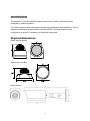
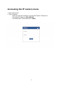
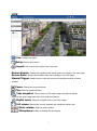
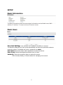
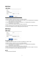
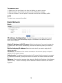
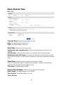
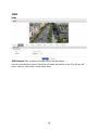
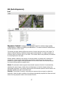
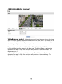
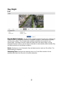
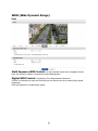
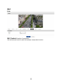
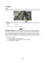
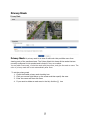
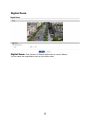
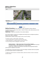
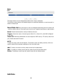
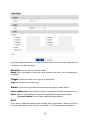
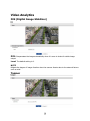
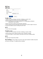
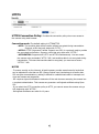
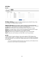
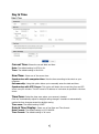
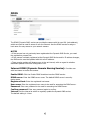
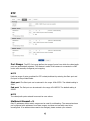
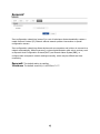
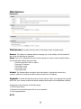
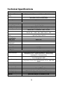
Menu set up manual for the Xeno IP camera range
Contents
OVERVIEW .............................................................................................................................. 4
Physical Dimensions ....................................................................................................... 4
Key Features .................................................................................................................. 5
System Requirements..................................................................................................... 5
Accessing the IP camera menu.................................................................................................. 6
LIVE ............................................................................................................................... 7
SETUP ............................................................................................................................ 8
Basic Information ........................................................................................................... 8
Basic Users .............................................................................................................. 8
Basic-Network ....................................................................................................... 10
Basic-Date & Time................................................................................................. 11
Video Streams ............................................................................................................. 11
Image-Basic .......................................................................................................... 15
WDR (Wide Dynamic Range)................................................................................. 21
BLC ....................................................................................................................... 22
Motion Detection .......................................................................................................... 27
Trigger ......................................................................................................................... 28
System ......................................................................................................................... 28
Action ........................................................................................................................... 29
Video Analytics ............................................................................................................. 36
DIS (Digital Image Stabilizer) ....................................................................................... 36
Tamper ........................................................................................................................ 36
System Options ............................................................................................................ 38
Users ..................................................................................................................... 38
HTTPS ................................................................................................................... 40
IP Filter ................................................................................................................. 41
Day & Time ........................................................................................................... 42
TCP/IP................................................................................................................... 43
RTP ....................................................................................................................... 46
Technical Specifications ......................................................................................... 52
Troubleshooting ..................................................................................................................... 54
Upgrading the Firmware ............................................................................................... 54
General Troubleshooting .............................................................................................. 54
OVERVIEW
This camera is a Full-HD 1080/60p network camera with a built-in web based viewer
accessible by multiple browsers
This camera supports dual compression formats and simultaneous triple streaming. The two
standard compression formats include H.264 and MJPEG. The triple streams can be
configured to a variety of resolutions, bit rates and frame rates.
Physical Dimensions
Plastic internal domes
Vandal dome housing
Bullet housing
Key Features
1. Sony Exmor™ CMOS Full-HD Sensor
• IMX140LQJ
• 1/2.8 inch RGB Bayer
• MIPI CSI-2 Serial Out
2. Sony Xarina™ Image Signal Processor
• True WDR
• 2D/3D Noise Reduction
• Digital Image Stabilizer
3. Sony Xarina™ H.264 Encoding, MJPEG Encoding
• Up to 1920x1080@60fps
• Dual 1920x1080@30fps at True WDR Mode
• TCP/IP, UDP, HTTP, RTP, RTSP, IPv4/v6…….
4. Built-In Web Browser
• Active X
• Support IE/Chrome/Safari
5. ONVIF Compliant
• Profile S
• Support ONVIF Compatible 3rd Party VMS or NVR
System Requirements
1. Operating System
• Windows XP (32 bit) Professional Edition
• Windows 7, 8 (32/64 bit) Ultimate, Professional Edition
2. Processor
• Intel Core 2 Duo 2.4 GHz or higher (for using 1920*1080 30 fps)
• Intel Core i7 2.8 GHz or higher (for using 1920*1080 60 fps)
3. Memory
• 2 GB or higher
4. Resolution
• 1280X1024 pixels or higher (32 bit color)
5. Web Browser
• Microsoft Internet Explorer Ver. 7.0, 8.0, 9.0, 10.0
• Safari Ver. 4.0 (Plug-in free viewer only)
• Google Chrome Ver. 4.0 (Plug-in free viewer only)
Accessing the IP camera menu
1. Open Web browser
2. Type IP address
• Enter the camera’s IP address in the Internet Explorer® address bar.
• The default IP address is 192.168.0.10
• The default User ID and Password is admin
LIVE
Live: Displays live video.
Setup:
Enters setup menu.
Logout: Exit current login and/or Enter new login.
Stream Source: Specify the viewable video stream source to display in live view page.
Screen Ratio: Specify the viewable video size to display in live view page.
Manual Trigger: Used to start or stop the event out manually according to event
settings.
Pause: Freeze the current windows.
Play: Play the paused windows.
Take snapshot: Take a picture of the video image currently on display.
Supports the origin image size view, print, and save feature.
Digital zoom:
Supports a digital zoom in live video image.
Full screen: Expand the current windows into maximum monitor size.
Mute volume: Mute the audio volume.
Microphone: Enable or Disable the microphone.
SETUP
Basic Information
The Basic Information shows the camera basic information such as Model name, MAC
address, IP address, TV output mode and Firmware version.
Basic Users
User List Setting:
User accounts can be added or modified or removed.
The authority depends upon user group automatically and shows the permission status to
access the menus. The default user name / password are admin.
User Name: Shows the name which registered to access the camera.
User Group: Shows the assigned permission given to users.
Authority: Shows the permission status to access the menus.
• Click the Add, Modify, or Remove button for managing user account.
Add User
To add a new user:
1. Click the Add tab, and then new pop-up window appears.
2. Click in the User name box and type a new user name (1 to 14 alphanumeric characters).
• User names are not case sensitive.
3. Click in the Password box and type a password (1 to 8 alphanumeric characters).
• Passwords are case sensitive.
4. Click in the Confirm password box and retype a password.
5. Click in the User group box and select one of the groups you wish to assign to the user.
6. Click the OK button to save the settings and add a new user.
Edit User
To modify a user:
1. Select one of the User Name in the User List Setting you want to edit.
2. Click the Edit tab, and then new pop-up window appears.
3. Click in the Password box and type a password (1 to 8 alphanumeric characters).
• Passwords are case sensitive.
4. Click in the Confirm password box and retype a password.
5. Click in the User group box and select one of the groups you wish to assign to the user.
6. Click the OK button to save the settings and edit a user.
NOTE
The user name can’t be edit.
To remove a user:
1. Select one of the User Name in the User List Setting you want to remove.
2. Click the Remove tab. A dialog box appears with confirmation message.
3. Click the OK button. The user profile is removed from the User List Setting profile.
NOTE
The admin user name can’t be edited.
Basic-Network
IP Address Configuration:
The DHCP (Dynamic Host Configuration Protocol)
server has a feature that automatically assigns an IP address to the device if there is a
device on the network.
Obtain IP address via DHCP server: Select the choice box if you want to assign the
IP address from DHCP server automatically, and then the remaining setting are read-only
text.
Use the following IP address: Select the choice box if you want to assign the IP
address manually.
IP address: The address of the camera connected to the network. Specify a unique IP
address for this network camera.
Subnet mask: The address that determines the IP network that the camera is connected
to (relative to its address). Specify the mask for the subnet the network camera is located
on.
Gateway: The router that accesses other networks. Specify the IP address of the Gateway
(default router) used for connecting devices attached to different networks and network
segments.
Basic-Date & Time
Current Time: Shows the current date and time.
Date: The default setting is 1970-01-01.
Time: The default setting is 00:00:00.
New Time:
Select one of the server time.
Synchronize with computer time: Sets the time according to the clock on your
computer.
Set manually: Using this option allows you to manually enter the date and time.
Synchronize with NTP Server: This option will obtain the correct time from an NTP
server every 60 minutes. The NTP server's IP address or host name is specified in the time
server.
Time Zone:
Select the time zone where your camera is located.
Click the "Automatically adjust for daylight saving changes" checkbox to automatically
update the time changes caused by daylight saving.
Time zone: The default setting is GMT.
Date & Time Display:
Select one of the Date and Time format.
Date Format: The default setting is YYYY-MM-DD.
Time Format: The default setting is 24 hours.
Video Streams
Video Source:
Specify the system performance. Depending on capture mode, each
stream configuration will be affected and the streaming will be adjusted under system
performance automatically.
Mode: The default mode is 1920x1080 Max. 60fps, for True-WDR usage set the capture
mode to 1920x1080 Max. 30fps.
Video Stream1:
Configures the H.264 setting value for stream1.
Compression: Selects the stream profile that is to be used for transmissions. The default
setting is Baseline Profile.
Resolution: Specified as the number of pixel-columns (width) by the number of pixel-rows
(height). The Resolution can be adjusted in the range from 320x240 to 1920x1080. The
default setting is a 1920x1080.
Frame rate: Indicates the number of fps (frame per second) available for the video
stream configuration. The Frame rate can be adjusted in the range from 1 to 30 fps. The
default setting is 30 fps.
GOP size: The GOP size can be adjusted in the range from 1 to 60 fps. The default setting
is 30 fps.
Bitrate control: The bit rate can be set as VBR (Variable Bit Rate) or CBR (Constant Bit
Rate).
• VBR: Automatically adjusts the bit rate according to the image complexity, using up
bandwidth for increased activity in the image, and less for lower activity in the monitored
area.
• CBR: Allows you to set a fixed target bit rate that consumes a predictable amount of
bandwidth. As the bit rate would usually need to increase for increased image activity, but in
this case the frame rate and image quality are affected negatively.
Bitrate: Indicates the quality of the video stream (rendered in kilobits per second). The
higher value means the higher video quality and bandwidth required. The Compression can
be adjusted in the range from 100 to 12000 kbps. The default setting is 4000 kbps.
Video Stream2:
Configures the MJPEG setting value for stream2.
Compression: The default setting is MJPEG.
Resolution: Specified as the number of pixel-columns (width) by the number of pixel-rows
(height). The Resolution can be adjusted in the range from 320x240 to 640x480. The
default setting is a 640x360.
Frame rate: Indicates the number of fps (frame per second) available for the video
stream configuration. The Frame rate can be adjusted in the range from 1 to 30 fps. The
default setting is 5 fps.
Quality: Automatically adjusts the compression rate to guarantee the image. The default
setting is 60.
Video Stream3:
Configures the H.264 setting value for stream3.
Compression: Selects the stream profile that is to be used for transmissions. The default
setting is High Profile.
Resolution: Specified as the number of pixel-columns (width) by the number of pixel-rows
(height). The Resolution can be adjusted in the range from 320x240 to 1920x1080. The
default setting is a 1280x720.
Frame rate: Indicates the number of fps (frame per second) available for the video
stream configuration. The Frame rate can be adjusted in the range from 1 to 30 fps. The
default setting is 10 fps.
Gop size: You can select the number of Group of pictures (I-frame, P-frame).
The Gop size can be adjusted in the range from 1 to 20 fps. The default setting is 10 fps.
Bitrate control: The bit rate can be set as VBR (Variable Bit Rate) or CBR (Constant Bit
Rate).
Bitrate: Indicates the quality of the video stream (rendered in kilobits per second). The
higher value means the higher video quality and bandwidth required. The Compression can
be adjusted in the range from 100 to 12000 kbps. The default setting is 1000 kbps.
Image-Basic
Appearance Control:
The image appearance allows you to adjust the camera
setting parameters and change the camera orientation. All of parameters are
recommended to be modifying for good image quality suitable for installation place.
Brightness: Controls the brightness of detail in a scene. The brightness can be adjusted
in the range 1~16. The default setting is 1.
Contrast: Controls the contrast of detail in a scene. The contrast can be adjusted in the
range 1~16. The default setting is 9.
Saturation: Controls the saturation of detail in a scene. The saturation can be adjusted in
the range 1~16. The default setting is 9.
Hue: Controls the hue of detail in a scene. The hue can be adjusted in the range 1~7. The
default setting is 4.
Sharpness: Controls the sharpness of detail in a scene. The sharpness can be adjusted in
the range 1~8. The default setting is 5.
Enable flip image: Rotate the camera image 180 degrees vertically.
Enable mirror image: Reflect duplication of camera image.
OSD
OSD Control: Click checkbox of Enable OSD to use this feature.
You can input desired words on Text blank and select the location of the Text (left-up, leftdown, right-up, right-down) on drop down menu.
AE (Auto Exposure)
Exposure Control: Configure the exposure control to suit the image quality
requirements in relation to lighting considerations. This camera features automatic and
manual exposure control mode.
The shutter and gain settings affect the amount of motion blur and noise in the image. To
adapt to different lighting, available storage space and bandwidth, it is often necessary to
prioritize either low motion blur or low noise. This camera allows using different prioritization
in normal light and in low light.
Shutter speed is related to the amount of time the shutter is opened and is measured in
seconds (s). A slow shutter speed allows more light to reach the sensor and can help
produce a brighter image in low light situations. On the other hand, a slow shutter speed
can cause moving objects to appear blurry.
Mode: The automatic mode supports the automatic exposure function for automatically
adjusting the sensor’s gain, shutter time and diaphragm so that the images achieve the
appropriate brightness. The manual mode supports the manual exposure control function for
manually adjusting the gain and shutter time.
Priority: This function is used for controlling the exposure time and gain to adjust the
luminance. Under the dark conditions, this camera automatically expands the frame rate and
enters the long exposure mode in this normal AE mode.
Shutter: Used to for controlling the gain while keeping the shutter time fixed to adjust the
luminance.
Min. Shutter: Adjust the Min. Shutter speed in the range 1/500~1/135,000 sec
Max. Shutter: Adjust the Max. Shutter speed in the range 1/10~1/10,000 sec
Gain: Gain is the amount of amplification applied to the image. A high gain may provide a
better image in low light situations but will increase the amount of image noise. The gain
can be adjusted in the range 1.2~54 dB
Min. Gain: Adjust the Min. Gain in the range 1.2~54 dB
Max. Gain: Adjust the Max. Gain in the range 1.2~54 dB
Auto Iris: This function is used for controlling the shutter time, gain and diaphragm of the
mechanical iris lens to adjust the luminance. In this mode, it is also possible to adjust the
luminance using the gain and iris diaphragm while keeping the exposure time fixed.
AWB (Auto White Balance)
White Balance Control:
White balance control is used to make colors in the image
appear the same regardless of the color temperature of the light source. This camera can be
set to automatically identify the light source and compensate for its color. Alternatively,
select the type of light source from the drop-down list.
Mode: Configure the options for White Balance. The default setting is ATW-Indoor.
Cb Gain: Adjusts the picture output in the blue range. The White balance B gain can be
adjusted in the range 1~256, where a higher value produces a higher blue image. The
default setting is 20.
Cr Gain: Adjusts the picture output in the red range. The White balance R gain can be
adjusted in the range 1~256, where a higher value produces a higher red image. The
default setting is 20.
Day/Night
Day & Night Control: The IR cut filter prevents infrared (IR) light from reaching the
image sensor. In poor lighting conditions, for example at night, or when using an IR lamp,
set the mode to Night. This increases light sensitivity and allows the product to “see”
infrared light. The image is shown in black and white when the mode is Night. If using
Automatic Exposure control, set the mode to Automatic to automatically switch between Day
and Night according to the lighting conditions.
Mode: Configure as one of Automatic, Day and Night mode to transit an IR cut filter. The
default setting is Automatic.
Switching Time: Configure the switching time of an IR cut filter transition for the
specified dwell time from the point of transition detection.
WDR (Wide Dynamic Range)
Multi Exposure WDR Control: In high-contrast scenes such as against a back
light, this function reduces overexposure and underexposure.
Digital WDR Control: Augmenting Tone Reproduction-Extension.
ATR-EX is controlled by slope and contrast gain on the tone curve as tracking level grade
brightness.
Click the checkbox to enable defog mode.
BLC
BLC Control: Backlight Compensation.
Set the Mode and Level to enable the backlight compensation function.
DNR
2D-NR / 3D-NR Control:
The noise reduction (NR) function eliminates image
noise in order to improve the image quality of the cameras. They consist of the 2D-NR
function which eliminates noise for a single frame while monitoring the correlation of the
pixels, and links with 3D-NR to suppress noise.
The 3D-NR function which reduces noise using the frame memory while factoring in the
correlation between multiple frames.
Mode: The default setting is On.
Level: Configure one of Level 1, Level2, Level3 and Level4.
Corridor
Corridor Control: The corridor format allows you to get a vertically oriented video
stream from the camera. The video is adapted to the monitored area, maximizing image
quality while eliminating bandwidth and storage waste. The Corridor Format is even more
useful for modern HDTV network cameras that deliver a 16:9 aspect ratio since the resulting
image will have a 9:16 aspect ratio – can be used for narrow corridors, hallways or aisles.
To set
1.
2.
3.
the Corridor format
Check the Enable corridor checking box.
Rotate the camera position compare to normal positioning.
Select the Rotation degrees.
Privacy Mask
Privacy Mask:
A privacy mask is an area of solid color that prohibits users from
viewing parts of the monitored area. The Privacy Mask List shows all the masks that are
currently configured in this product and indicates if they are enabled.
You can add a new mask, re-size the mask with the mouse, and give the mask a name. The
color of privacy mask will be set automatically after Save.
To set the privacy mask
1. Check the Enable privacy mask checking box.
2. Click your mouse right button on the screen and then specify the area.
3. Enter the name and then click Save.
4. If you want to delete an mask area in the list, click the
icon
Digital Zoom
Digital Zoom:
Click checkbox of Enable digital zoom to use this feature.
You can select the magnification level on drop down menu.
Motion Detection
Motion Detection: Motion detection is used to generate an alarm whenever
movement occurs (or stops) in the viewer. A total of 8 Motion and/or Mask windows can be
created and configured.
Sensitivity: Configure the sensitivity for the motion detection.
Once motion detection windows are configured, this camera can be configured to perform
actions when motion is detected.
Possible actions include uploading images, alarm out and E-mailing.
To create a motion or mask window, follow steps:
1. Click the right button of mouse to see the mouse menu.
2. Select New Motion (or Mask) Window in the mouse menu.
3. Click and drag mouse to designate a motion area.
• Include windows — define areas where motion should be detected
• Exclude windows — define areas within an Include window that should be ignored
• Threshold: Configure the threshold for the motion detection.
• Dwell Time: Configure the hold time an event lasts for the specified hold time
from the point of detection of a motion.
To exclude parts of the include window, select the Configure excluded window and position
the exclude window within the include window.
To delete an include window or exclude window, select the window in the list of windows
and click Delete.
Trigger
System
System booting: This is used to trigger the event every time the Network Camera is
started.
Dwell time: The default setting is 3 seconds.
Manual
Manual Trigger:
The Manual Trigger features an alarm out signaling, JPEG file
transfer to FTP server, and sends email to SMTP server whenever operator clicks Manual
Trigger button in the Live View window.
NOTE
Dwell time means how long time the alarm output signal hold on as an output signaling
source.
Network
Net Loss: This is used to trigger the event every time the network connection fails.
Click the check box to activate the Network Loss event.
Dwell time: The default setting is 3 seconds.
Action
E-Mail
E-Mail(SMTP): Use the Simple Mail Transfer Protocol (SMTP) server to send an email
notification when an event server is activated. The camera can be configured to send
event and email messages via SMTP.
If your mail server requires authentication, click the Use (SMTP) authentication checkbox for
use authentication to log in to this server.
Sender: Click in the Sender box and enter the Email address as the sender.
Interval: Enter the Email sending time interval after event occurred.
Aggregate events: Enter the number of events for Email sending. If the event numbers
are reached the setting value, Email sending is available.
Use Email server: Click the Use Email server checkbox and provide the following
information for Email server.
Mail Server: Enter the host names or IP addresses for your mail servers in the fields
provided.
NOTE
If a host name is used, a valid DNS server must be specified in the Network-Basic settings.
Port: Enter the SMTP server port number for the SMTP Server. The Port number can be
adjusted in the range 1-65535. The default setting is 25.
NOTES
- If your mail server requires authentication, click the Use (SMTP) authentication checkbox
for use authentication to log in to this server.
- Please consult with your network administrator, if you want to change the port number.
Use (SMTP) authentication: If your mail server requires authentication, click the Use
(SMTP) authentication checkbox for use authentication to log in to this server.
User name: Enter the User name as provided by your network administrator.
Password: Enter the Password as provided by your network administrator.
Login method: Select one for SMTP authentication method allowed.
NOTES
- If a PLAIN or LOGIN mechanism is negotiated, the camera sends user name and password
to the SMTP server.
- The LOGIN mechanism is supported by Microsoft, as well as by some other clients. Most
other clients support the PLAIN authentication mechanism.
- Since the vast majority of Email clients support only PLAIN or LOGIN, mail server
administrators will probably want to consider using STARTTLS to provide an encryption
"tunnel" between the client and server, to protect the user name and password.
Receiver List: Enter the recipient’s email address as the receivers.
Receiver1~8: Enter the recipient’s email address as the receiver to test.
E-Mail(SMTP) Test: Enter the recipient's email address and click the Test button to
test that the mail servers are functioning and that the email address is valid. When the
setup is complete, the connection can be tested by clicking the Test button.
Receiver: Enter the recipient’s email address as the receiver to test.
FTP
FTP Setting: FTP notification will save a file on the specified FTP server. Click the
Enable FTP checkbox and provide the following information for FTP notification.
Server: Enter the IP address or host name of the target FTP server.
• Passive Mode: Under normal circumstances the network camera simply requests
the target FTP server to open the data connection. Checking this box issues a PASV
command to the FTP server and establishes a passive FTP connection; whereby the network
camera actively initiates both the FTP control and data connections to the target server. This
is normally desirable if there is a firewall between the network camera and the target FTP
server.
Port: Enter the port number used by the FTP server. The Port number can be adjusted in
the range 1-65535. The default setting is 21.
Remote directory: Specify the path to the directory where the uploaded images will be
stored. If this directory does not already exist on the FTP server, there will be an error
message when uploading.
User name: : Enter the User name as provided by your network administrator.
• Anonymous login: Click the Anonymous login checkbox to permit anyone to
access FTP server.
Password: Enter the Password as provided by your network administrator.
NOTE
If you permit to login FTP server by anyone without password, click the Anonymous login
checkbox.
JPEG Setting: Configure the JPEG to send the FTP server.
Pre-event: Defines how many JPEG file will be made during 0-3 seconds before the event
is generated.
Post-event: Defines how many JPEG file will be made during 0-3 seconds after the event
is generated.
Prefix file name: Click in the Prefix file name box and type a name for JPEG image file (1
to 32 alphanumeric characters).
Additional suffix: Provide additional information for JPEG image file.
Rule
This page shows current configuration status when event is activated.
The common event actions will upload images to a specified destination or send an email or
active an output port
Event Rule List:
An event type is a set of parameters describing how the camera will
perform certain actions. Event type may be set up as Triggered according to requirements.
Name: Shows the descriptive name provided by the user.
Trigger: Shows the source of event type as Alarm-In-1, Alarm-In-2, and VMD configured
by the user.
Event Out: Shows the destination of event output as SMTP server, FTP server, Alarm-out
port, Audio alert and SD record.
NOTE
To add new event, click the Add button. This button opens new dialog window, which are
used to make all the necessary settings for the new event map.
Add: To add a new event rule list, select it and click the Add button.
Edit: To modify an existing event map list, select it and click the Edit button.
Delete: To delete an event map list, select it and click the Delete button.
Add Rule
Event Map page provides how to configure the event action if there is event triggering such
as Alarm-In and Manual trigger.
General: Enter the user favorite event name.
Name: Click in the Name box and type a user favorite event name (1 to 31 alphanumeric
characters).
Trigger: Shows the Event source type to be configured.
Type: Selects the Event source type.
Action: The Event Out provides that the camera will perform certain actions.
Active output port: Click the Active output port checkbox to enable the Alarm out port.
Email: Click the Email checkbox to enable the emailing below each email address.
• To email address: Click the each email addresses checkbox.
NOTE
If you want to additional message when emailing, click in the Subject / Additional Info box
and type a description for the text you are creating (0 to 255 alphanumeric characters).
FTP & JPEG: Click the FTP & JPEG checkbox to enable the image uploading to FTP
server using JPEG image.
Video Analytics
DIS (Digital Image Stabilizer)
DIS: Compensates the image automatically when it is seen to shake for stable image
output.
Level: The default setting is 8.
NOTE
Mitigate the degree of image vibration when the camera vibrates due to the external factors
such as wind.
Tamper
Tamper: Camera Tampering can generate an alarm whenever the camera is repositioned
or severely defocused. To send an alarm, for example an email, an event map must be set
up.
Dwell time: The default setting is 3 seconds.
NOTE
The Dwell time that must elapse before an alarm is generated. This can help prevent false
alarms for known conditions that affect the image.
To configure the camera to send an alarm when tampering occurs:
1. Go to Event Map > Add.
2. Select Event In Type.
3. Set Event Out for notification of an image changing if the lens is repositioned or
rendered severely out of focus.
System Options
Users
User List:
User accounts can be added or modified or removed. The authority depends
upon user group automatically and shows the permission status to access the menus. The
default user name / password are admin.
User Name: Shows the name which registered to access the camera.
User Group: Shows the assigned permission given to users.
Authority: Shows the permission status to access the menus.
• Click the Add, Modify, or Remove button for managing user account.
Add User
To add a new user:
1. Click the Add tab, and then new pop-up window appears.
2. Click in the User name box and type a new user name (1 to 14 alphanumeric characters).
• User names are not case sensitive.
3. Click in the Password box and type a password (1 to 8 alphanumeric characters).
• Passwords are case sensitive.
4. Click in the Confirm password box and retype a password.
5. Click in the User group box and select one of the groups you wish to assign to the user.
6. Click the OK button to save the settings and add a new user.
Edit User
To Edit a user:
1. Select one of the User Name in the User List Setting you want to edit.
2. Click the Modify tab, and then new pop-up window appears.
3. Click in the Password box and type a password (1 to 8 alphanumeric characters).
• Passwords are case sensitive.
4. Click in the Confirm password box and retype a password.
5. Click in the User group box and select one of the groups you wish to assign to the user.
6. Click the OK button to save the settings and edit a user.
NOTE
The user name can’t be edited.
To Delete a user:
1. Select one of the User Name in the User List Setting you want to delete.
2. Click the Remove tab. A dialog box appears with confirmation message.
3. Click the OK button. The user profile is removed from the User List Setting profile.
NOTE
The admin user name can’t be edited.
User Setting:
Click the Enable anonymous viewer login checkbox to enable anonymous
user login to the camera. The default setting is disabled.
HTTPS
HTTPS Connection Policy: Provides the connection policy when user access to
the camera using web browser.
Connection mode: The default setting is HTTP&HTTPS.
• HTTP: The sensitive data will be transfer without encrypted during transmission.
Supports a URL that only starts with "HTTP: "
• HTTPS: HTTPS (Hypertext Transfer Protocol over SSL) is a protocol used to provide
the encrypted transmission. Supports a URL that only starts with "HTTPS: "
• HTTP&HTTPS: Supports both HTTP and HTTPS simultaneously. You can access
the camera using a standard “HTTP:” URL, but sensitive data is not encrypted during
transmission. To ensure that sensitive data is encrypted, you must use a secure
"HTTPS: " URL.
NOTES
- To ensure security on the internet, all web browsers provide several security levels that
can be adjusted for site that use SSL (Secure Socket Layer) technology to transfer data.
SSL encrypts communications, making it difficult for unauthorized users to intercept and
view user names and passwords.
- SSL requires signed certificates to determine if the web browser accessing the camera has
a required authentication. This camera can generate a self-signed certificate using Open
SSL.
- If you select the HTTP connection policy to HTTP, you cannot access the camera using a
URL beginning with “HTTPS:”
- Self-signed certificates are valid for 10 years.
IP Filter
IP Filter Setting:
Provides the IP filtering elements such as On/Off, Priority, Policy
and IP Ranges. The default setting is disabling.
Enable IP filtering: Click the Enable IP filtering checkbox to enable the IP address
filtering function. This dialog allows you to add new allowed/denied IP addresses. These can
be added whole ranges (subnets) of IP address can be added directly.
On/Off: Click the checkbox to active the settings (Priority, Policy, and IP ranges).
Priority: The number means a priority if there are duplicated IP address each IP ranges.
Policy: Determines the filtering attribute of the IP address selected.
Start IP: Enters the start IP address to ALLOW/ DENY in the IP range selected.
End IP: Enters the end IP address to ALLOW/ DENY in the IP range selected.
NOTES
To add a subnet of network addresses, these must be added in CIDR (Classless InterDomain Routing) notation. For example: entering 192.168.1.0/24 will add all the addresses
in the range 192.168.1.1 to 192.168.1.254. Please contact with your network administrator
for more detail.
• If you are accessing the network camera via a proxy server, the IP address for the
proxy server must be added as an allowed address.
Day & Time
Current Time: Shows the current date and time.
Date: The default setting is 1970-01-01.
Time: The default setting is 00:00:00.
New Time:
Select one of the server time.
Synchronize with computer time: Sets the time according to the clock on your
computer.
Set manually: Using this option allows you to manually enter the date and time.
Synchronize with NTP Server: This option will obtain the correct time from an NTP
server every 60 minutes. The NTP server's IP address or host name is specified in the time
server.
Time Zone: Select the time zone where your camera is located.
Click the "Automatically adjust for daylight saving changes" checkbox to automatically
update the time changes caused by daylight saving.
Time zone: The default setting is GMT.
Date & Time Display:
Select one of the Date and Time format.
Date Format: The default setting is YYYY-MM-DD.
Time Format: The default setting is 24 hours.
TCP/IP
IP Address: The DHCP (Dynamic Host Configuration Protocol) server has a feature that
automatically assigns an IP address to the device if there is a device on the network.
Obtain IP address via DHCP server: Select the choice box if you want to assign the
IP address from DHCP server automatically, and then the remaining setting are read-only
text.
Use the following IP address: Select the choice box if you want to assign the IP
address manually.
IP address: The address of the camera connected to the network. Specify a unique IP
address for this network camera.
Subnet mask: The address that determines the IP network that the camera is connected
to (relative to its address). Specify the mask for the subnet the network camera is located
on.
Gateway: The router that accesses other networks. Specify the IP address of the
Gateway(default router) used for connecting devices attached to different networks and
network segments.
IPv6 Address Configuration:
Check this box to enable IPv6 address
configuration. Other settings for IPv6 are configured in the network router.
DNS Configuration:
DNS (Domain Name Service) provides the translation of host
names to IP addresses on your network.
Obtain DNS server via DHCP: Select the choice box if you want to use the DNS server
settings provided by the DHCP server automatically, and then the remaining setting are
read-only text.
Use the following DNS address: Select the choice box if you want to use the desired
DNS server manually.
Domain name: Enter the domain to search for the host name used by the network
camera.
Primary DNS server: Enter the IP address of the primary DNS server.
Secondary DNS server: Enter the IP address of the secondary DNS server.
Hostname Configuration: This camera can be accessed using a host name
instead of an IP address. The host name is usually the same as the assigned DNS name.
Port: Allows the user to access the camera using web browser encrypted communication.
HTTP port: The default HTTP (Hypertext Transfer Protocol) port number is 80 and can be
changed to any port within the range 1024-65535.
HTTPS port: The default port number is 443 and can be changed to any port within the
range 1024-65535.
RTSP port: RTSP (Real Time Streaming Protocol) allows a connecting client to start a
video stream. The default setting is 7070 and can be changed to any port within the range
1024-65535.
DDNS
The DDNS (Dynamic DNS) service can provide the camera with its own URL (web address),
which can then be used to access it over the Internet. Use the DDNS service to assign a
host name for easy access to your network camera.
NOTES
• If the camera has not previously been registered at the Dynamic DNS Service, you need
the registration process first.
• If the camera is already registered at the Dynamic DNS Service and its IP address changes,
the DNS service must be updated with this new IP address.
• These regular updates will always occur at the set interval, with no regard to whether
automatic updates have been configured or not.
Internet DDNS (Dynamic Domain Naming Service):
Provides user
with host name to access the camera.
Enable DDNS: Click the Enable DDNS checkbox to active DDNS service.
DDNS server: Enter the DDNS server name. The default DDNS server is securitydevice.name
Registered host: Enter the registered host name.
User name: Enter the registered user name to be used for accessing the DDNS server.
Password: Enter user password to be used for accessing the DDNS server.
Confirm password: Enter user password again to confirm.
Interval: Set the interval at which to regularly update the Dynamic DNS service.
The default setting is 1 hour.
RTP
Port Range: The RTP Port range defines the range of ports from which the video/audio
ports are automatically selected. This feature is useful if the camera is connected to a NAT
router with manually configured port mapping.
NOTE
Limit the range of ports permitted for RTP unicast/multicast by entering the Start port and
End port in the provided fields.
Start port: The Start port can be entered in the range 1024-65532. The default setting is
5008.
End port: The End port can be entered in the range 1024-65532. The default setting is
50999.
NOTE
The video/audio ports entered here must be even values.
Multicast-Stream1~3:
Only IP addresses within certain ranges can be used for multicasting. The camera has been
pre-configured with addresses from these ranges, and does not normally need to be
reconfigured. If an address does need to be changed, please contact your network
administrator.
Destination IP: Click in the destination IP box and type IP address.
NOTES
- Multicast addresses are allocated according to these IANA policies.
- The default setting IP address is 231.1.128.20
RTP port: The RTP port can be entered in the range 1024-65532. The default setting is
5000.
NOTE
The RTP port entered here must be even values.
TTL: The TTL can be entered in the range 1-255. The default setting is 1.
NOTES
• TTL (Time To Live) If IP packets (i.e. data) fail to be delivered to their destination within a
reasonable length of time (which could be for various reasons), this setting tells network
routers when to discard the packet.
• The value is usually measured in 'hops', i.e. the number of network routers that can be
passed before the packet arrives at its destination or is dropped.
UPnP
UPnP is enabled by default, and the network camera then is automatically detected by
operating systems and clients that support this protocol.
UPnP:
Click the Enable UPnP checkbox to disable the UPnP. The default setting is
enabling.
Friendly name: Click in the Friendly name box and type a description for the text you are
creating (1 to 32 alphanumeric characters). If your computer is also enabled, the camera is
automatically detected and a new icon is added to “Model Name-MAC address”.
NOTE
UPnP must also be enabled on your Windows computer. To do this, open the Control Panel
from the Start Menu and select Add/Rename programs. Select Add/Remove Windows
Components and open the Networking Services section. Click Details and then select UPnP
as the service to add.
Zeroconf
Zero configuration networking (zeoconf) is a set of techniques that automatically creates a
usable Internet Protocol (IP) network without manual operator intervention or special
configuration servers.
Zero configuration networking allows devices such as computers and printers to connect to a
network automatically. Without zeroconf, a network administrator must set up services, such
as Dynamic Host Configuration Protocol(DHCP) and Domain Name System(DNS), or
configure each computer’s network settings manually, which may be difficult and timeconsuming.
Zeroconf: The default setting is enabling.
IP Address: The default zeroconf ip is 169.254.117.177
Maintenance
Maintenance: Provides software reset of the camera when troubleshooting.
Restart: The camera is restarted without changing any of the setting. Use this method if
the unit is not behaving as expected.
Reset: The unit is restarted and most current settings are reset to factory default values,
but the following settings does not reset.
• The boot protocol (DHCP or static)
• The static IP address
• The default router
• The subnet mask
• The system time
Default: The Default button should be used with caution. Pressing this returns the
camera’s settings to the factory default values including the IP address.
Upgrade:
Provides the latest firmware into this camera. When you upgrade the firmware
with a file, your camera receives the latest available functionality and unparalleled reliability.
Upgrades the new firmware as following steps;
1. Click Browse button.
2. Browse to the desired firmware file on your computer.
3. Click Upgrade button.
NOTE
Do not disconnect power to the unit during the upgrade. The unit restarts automatically
after the upgrade has completed. (2~3 minutes)
Setup Export: Save all parameters and user-defined scripts to a backup file. Click the
Backup button to take a backup of all the parameters, and any user-defined script.
Setup Import: Use a saved backup file to return the unit to a previous configuration.
Click the Browse button to locate the saved backup file and then click the Restore button.
NOTE
Backup and Restore can only be used on the same unit with running the same firmware.
This feature is not intended for the configuration of multiple units or for firmware upgrades.
Log & Report
Log & Report:
The log files records event in the unit since the last system restart and
can be a useful diagnostic tool when troubleshooting. The Report contains important
information about the server.
System Log: Provides the system log information.
Event Log: Provides the events log information.
Server Report: Provides the information about the server status and should be included
when requesting report. Information be found here includes the camera’s firmware version,
MAC address, system information, IP address and network connections.
Technical Specifications
IMAGE
Image Sensor
Number of Effective
Pixels
Min. Illumination
Scanning Mode
S/N Ratio
CAMERA
Wide Dynamic Range
Day and Night Mode
Noise Reduction
Auto Exposure Mode
Shutter Speed Control
Gain Control
Auto White Balance
Mode
Back Light
Compensation
Image Effect
Privacy Mask
Digital Image
Stabilization
Tamper
Video Motion Detection
Corridor Format
Defog
NETWORK
Video Compression
Video Resolution
Video Frame Rate
Video Streaming
Audio Sample Rate
Audio Bit Rate
FTP Uploading
Event In
Event Out Notification
Login Authority
Event Buffering
Manual Trigger
Security
Network Time Sync
Sony 1/2.8” 2.3Megapixel RGB Bayer Array CMOS Sensor
1920(H) x 1080(V) approx. 2.07M pixels (Full-HD mode)
Colour Mode: 0.15 lx at 50IRE/30fps
B/W Mode: 0.09 lx at 50IRE/30fps
Progressive Scan
54dB
Multi-Exposure WDR, ATR-EX
Automatic, Day, Night
2D-NR, 3D-NR
Automatic (Priority: Frame rate/Low noise), Manual
Automatic: Min. 1/135,000 sec ~ Max. 1/60 sec
Manual: Min. 1/10,000 sec ~ Max. 1/10 sec
Automatic: Min. 1.2dB ~ Max. 54dB
Manual: Min. 1.2dB ~ Max. 54dB, Default 1.2dB
ATW-Indoor/Outdoor, Shade, Clear sky, Fluorescent light,
Light bulb, Flame, Manual
On/Off
Mirror, Flip
Max.8 Area Selection
On/Off
On/Off
Max.4 Area Selection
90°/270°
On/Off
H.264(High, Main, Base line profile), MJPEG
1920x1080(Full-HD), 1280x1024(SXGA), 1280x720(HD),
704x480(4CIF/NT), 704x576(4CIF/PAL), 640x480(VGA),
352x288(CIF), 320x240(QVGA)
Full-HD Capture Mode : Up to 60fps@1920x1080,
Dual 30fps@1920x1080
Simultaneously H.264 and MJPEG
Independent Frame Rate and Bandwidth Control, VBR/CBR
Mode
8kHz
64kbps
MJPEG Still Image
Onboot/Network Loss/Tampering/Motion
E-mail, FTP
Administrator, Operator, Guest
FTP : Pre/Post Event Time: 0~30sec, FPS: 1~2 fps
Still Image Capture
Multi User Authority, IP Filtering, HTTPS
Synchronize Computer/NTP Server, Manual
Software Reset
Auto Recovery
Remote Upgrade
Protocols
Restart, Reset, Factory Default
Backup, Restore
Using Web Browser
TCP/IP, UDP, IPv4/v6, HTTP, HTTPS, FTP, UPnP, RTP,
RTSP, RTCP, DHCP, ARP, Zeroconf
Client Software
Built-In Web, ONVIF Compatible 3rd Party VMS
Max. User Connection
10 Users
API Support
SDK, ONVIF Profile S Compliant
EXTERNAL IN/OUT (Optional)
Audio
Audio 3.5mm Line In, Audio 3.5mm Line Out
Ethernet
RJ-45(10/100Base-T)
OPERATION ENVIRONMENTS
Operating Humidity
0~90% (non-condensing)
Operating Temperature
-10 ~ +50
Power Supply
Power Consumption
DC12V, PoE(IEEE802.3af Compliant, Class3)
DC12V: 6W, PoE: 6W
Specifications are subject to change without notice in advance.
Troubleshooting
If you suspect a problem is being caused by incorrect configuration or some other minor
problem, consult the troubleshooting guide below.
Upgrading the Firmware
Firmware is software that determines the functionality of the network camera. One of your
first actions when troubleshooting a problem should be to check the current firmware. The
latest version may contain a correction that fixes your particular problem. The current
firmware version in your camera is displayed on the Basic Configuration or About. For the
latest firmware of the camera, please contact with your product administrator.
Detailed instructions on how to perform the upgrade process are provided with each new
release. See also the Maintenancen/ Upgrade for more information.
General Troubleshooting
The following list covers some of the problems that may be encountered and suggests how
to remedy them:
Symptom
Possible Causes or Corrective Actions
1. The camera cannot be accessed by some clients.
If using a proxy server, try disabling the proxy setting in your browser. Check all cabling
and connectors.
2. The camera works locally, but not externally.
Check if there are firewall settings that need to be adjusted. Check if there are router
settings that need to be configured.
3. Poor or intermittent network connection.
If using a network switch, check that the port on that device uses the same setting for the
network connection type (speed/duplex).
4. The camera cannot be accessed via a host name.
Check that the host name and DNS server settings are correct.
5. Not possible to log in.
When HTTPS is enabled, ensure that the correct protocol (HTTP or HTTPS) is used. When
attempting to log in, you may need to manually type in http or https in the browser's
address bar.
6. No image using Refresh and/or slow updating of images.
If images are very complex, try limiting the number of clients accessing the camera.
7. Images only shown in black & white.
Check the Video & Image setting.
8. Blurred images.
Refocus the camera.
9. Poor image quality.
Increased lighting can often improve image quality. Check that there is sufficient lighting
at the monitored location. Check all image and lighting settings.
10. Rolling dark bands or flickering in image.
Try adjusting the Exposure Control setting under AE and AWB part.
11. H.264 not displayed in the client.
Check that the correct network interface is selected in the Video & Image/Stream.
12. Multicast H.264 not displayed in the client.
Check with your network administrator that the multicast addresses used by the camera
are valid for your network. Check that the Enable multicast checkbox are enabled in the
System/Network/RTP tab. Checks with your network administrator to see if there is a
firewall preventing viewing.
13. Multicast H.264 only accessible by local clients.
Check if your router supports multicasting, or if the router settings between the client and
the server need to be configured. The TTL value may need to be increased.
14. Color saturation is different in H.264 and Motion JPEG.
Modify the settings for your graphics adapter. Please see the adapter's documentation for
more information.
15. Poor audio quality.
Too many users/clients connected to the camera may affect the sound quality adversely.
Try limiting the number of clients allowed to connect.
16. Distorted audio.
Check that the correct Audio Input source is selected. Select Microphone for a connected
external microphone. Select Line for a connected line in source.
NOTE
If you cannot find the help you require, please see the User's Manual, or contact with your
network administrator.