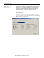
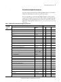
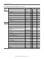
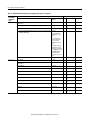
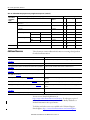
1
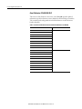
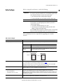
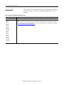
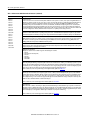
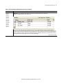
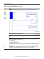
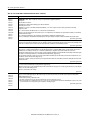
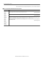
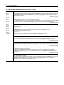
Release Notes ControlLogix Controllers, Revision 20 ControlLogix Controllers Catalog Numbers 1756-L61, 1756-L62, 1756-L63, 1756-L64, 1756-L65, 1756-L71, 1756-L72, 1756-L73, 1756-L74, 1756-L75 ControlLogix-XT Controller Catalog Numbers 1756-L63XT, 1756-L73XT GuardLogix Controllers Catalog Numbers 1756-L61S, 1756-L62S, 1756-L63S, 1756-LSP, 1756-L71S, 1756-L72S, 1756-L73S, 1756-L7SP GuardLogix-XT Controller Catalog Numbers 1756-L73SXT, 1756-L7SPXT Topic Page Compatible Software Versions 6 Before You Begin 7 Enhancements 8 Corrected Anomalies 11 Known Anomalies 19 Restrictions 24 Install the Controller Revision 25 Additional Memory Requirements 26 Additional Resources 32 2 ControlLogix Controllers, Revision 20 IMPORTANT Consider the following before upgrading the firmware on your Logix5000™ controller: • Before updating your controller, we strongly recommend that you review information pertinent to previous major firmware revisions. For example, when updating from revision 18.x to 20.x, view information in the following publications: - ControlLogix® Controllers (1756-L6x controllers), Revision 18 Release Notes, publication 1756-RN018 - ControlLogix Controllers (1756-L7x controllers), Revision 18 Release Notes, publication 1756-RN677 - ControlLogix Controllers (1756-L7x controllers), Revision 19 Release Notes, publication 1756-RN019 Firmware release notes contain material for all minor revisions subsequent to each major revision. If your controller, for example, is at revision 17.11, and not the last minor revision, 18.15, you should view all of the information for revisions 17.11...18.15 before updating to revision 20.x. Release notes are available at: http://www.rockwellautomation.com/literature. • After upgrading the firmware on your module, we strongly recommend that you retest and/or validate your application offline before going online. About This Publication This publication describes enhancements, anomalies (corrected and known), restrictions for ControlLogix controllers, firmware revisions 20.011…20.013, and GuardLogix® controllers, firmware revision 20.011…20.013. Information that has been added or changed since the last revision of this publication is indicated by a change bar as shown to the side of this paragraph. In addition to information specific to the most recent firmware revision, the information from previous minor revisions is retained in these release notes. We strongly recommend that you review the information provided regarding previous firmware revisions. We recommend that you do so because, if you are upgrading your firmware through multiple previous revisions, all of the information specific to all of the revisions is applicable. For example, if you need to upgrade your 1756-L71 controller from revision 20.012…20.013, all of the information specific to revisions 20.012…20.013 is applicable. Rockwell Automation Publication 1756-RN220C-EN-P - October 2012 ControlLogix Controllers, Revision 20 3 About Publication 1756-RN220C-EN-P This revision of the firmware release notes, 1756-RN220C, provides updated information specific to firmware revision 20.013 for all ControlLogix controllers. The controllers and catalog numbers included in firmware revision 20.013 are listed in this table. Table 1 - Controllers and Firmware Revisions Identified in Publication 1756-RN220C Cat. No. Major and Minor Revision No. 1756-L61 20.013 1756-L62 1756-L63 1756-L63XT 1756-L64 1756-L65 1756-L61S 1756-L62S 1756-L63S 1756-L71 20.013 1756-L71S 1756-L72 1756-L72S 1756-L73 1756-L73XT 1756-L73S 1756-L73SXT 1756-L74 1756-L75 Rockwell Automation Publication 1756-RN220C-EN-P - October 2012 4 ControlLogix Controllers, Revision 20 About Publication 1756-RN220B-EN-P This revision of the firmware release notes, 1756-RN220B, provides updated information specific to firmware revision 20.012 for all ControlLogix controllers. The controllers and catalog numbers included in firmware revision 20.012 are listed in this table. Table 2 - Controllers and Firmware Revisions Identified in Publication 1756-RN220B Cat. No. Major and Minor Revision No. 1756-L61 20.012 1756-L62 1756-L63 1756-L63XT 1756-L64 1756-L65 1756-L61S 1756-L62S 1756-L63S 1756-L71 20.012 1756-L71S 1756-L72 1756-L72S 1756-L73 1756-L73XT 1756-L73S 1756-L73SXT 1756-L74 1756-L75 Rockwell Automation Publication 1756-RN220C-EN-P - October 2012 ControlLogix Controllers, Revision 20 5 About Publication 1756-RN220A-EN-P This revision of the firmware release notes, 1756-RN220A, provides updated information specific to firmware revision 20.011 for all ControlLogix controllers. The controllers and catalog numbers included in firmware revision 20.011 are listed in this table. Table 3 - Controllers and Firmware Revisions Identified in Publication 1756-RN220A Cat. No. Major and Minor Revision No. 1756-L61 20.011 1756-L62 1756-L63 1756-L63XT 1756-L64 1756-L65 1756-L61S 1756-L62S 1756-L63S 1756-L71 20.011 1756-L72 1756-L72S 1756-L73 1756-L73XT 1756-L73S 1756-L73SXT 1756-L74 1756-L75 Rockwell Automation Publication 1756-RN220C-EN-P - October 2012 6 ControlLogix Controllers, Revision 20 Compatible Software Versions To use firmware revision 20.013, these minimum software versions are required. Table 4 - Compatible Software Versions Software Required Software Version, Min Compare Tool 3.20.02 ControlFLASH™ 11.00.00 FactoryTalk® AssetCentre 4.00.00 (CPR 9, SR3) FactoryTalk Services Platform 2.50.00 (CPR 9, SR5) FactoryTalk Activation 3.50.00 (CPR 9, SR5) RSLinx® Classic 2.59.01 (CPR 9, SR5) RSLinx Enterprise 5.50.04 (CPR 9, SR5) RSLogix™ 5000 20.01.00 (CPR 9, SR5) RSNetWorx™ for ControlNet 11.00.00 (CPR 9, SR5) RSNetWorx for DeviceNet RSNetWorx for EtherNet/IP For system requirements, go to http://www.rockwellautomation.com/rockwellsoftware/design/rslogix5000/sys req.html. Rockwell Automation Publication 1756-RN220C-EN-P - October 2012 ControlLogix Controllers, Revision 20 7 Before You Begin Before you upgrade your firmware, consider the following. IMPORTANT Loss of communication or power during a controller firmware upgrade may result in the controller rejecting the new firmware. If the controller firmware upgrade fails due to the conditions described, these corrective actions may be required: • Cycle controller power and successfully complete the upgrade. • If a nonrecoverable fault occurs, then return the controller for factory repair. IMPORTANT For the 1756-L7x controllers, if you meet both of the following conditions, you will not be able to update or connect through RSLogix 5000 software to your 1756-L7x controller using the USB port: • The controller is at firmware revisions 18, 19, or 1.008. • You are using a personal computer with an operating system that is 64-bit (Windows 7 operating system in 64-bit mode). If you meet both conditions, you will have to update the controller or connect through RSLogix 5000 software through different means, such as the Ethernet network. These preliminary actions are required before upgrading your controller firmware. Table 5 - Before You Begin If Then You are updating a 1756-L7x controller Before you begin updating your controller, check the status of your Secure Digital (SD) card. If your SD card is Then Unlocked You can successfully upgrade the firmware to the intended revision. Locked and the Load Image option is set to On Power Up You should unlock the SD card before beginning the upgrade. If the card is locked when you attempt to upgrade the firmware, the upgrade fails and the controller reverts to the firmware revision already stored on the SD card. Figure 1 - SD card - Unlocked and Locked Unlocked Locked Your controller is close to its limits of memory This revision may require more memory than previous revisions: • To see what components of your current project require more memory, see page 26. • RSLogix 5000 software, version 13.0 or later, lets you estimate the memory requirements of the controller offline. To upgrade to this revision, you may need to use a controller with a larger amount of memory. Your controller is at firmware revision 11 or earlier You must first upgrade to revision 12 or 13, before attempting to upgrade to revision 20.xx. Once you have your controller upgraded to revision 12 or 13, then you can upgrade the controller to revision 20.xx. Your controller meets both of these conditions: • It has nonvolatile memory • It is currently at revision 11.x or earlier Remove the CompactFlash card from the controller or check the Load Image option of the CompactFlash card. If it is set to On Power Up or On Corrupt Memory, first store the project with the Load Image option set to User Initiated. Otherwise, you may get a major fault when you upgrade controller firmware. This occurs because the On Power Up or On Corrupt Memory options cause the controller to load the project from nonvolatile memory. The firmware mismatch after the load then causes a major fault. Your controller is connected to a DH-485 network Disconnect it from the DH-485 network before you upgrade the controller firmware. If you upgrade the controller firmware while it is connected to a DH-485 network, communication on the network may stop. Rockwell Automation Publication 1756-RN220C-EN-P - October 2012 8 ControlLogix Controllers, Revision 20 These enhancements are available when you use ControlLogix and GuardLogix controllers, firmware revision 20.012, with RSLogix 5000 software, version 20.01.00. Enhancements Table 6 - Enhancements with Firmware Revision 20.012 Cat. No. Description 1756-L71S Software and firmware support added. 1756-L61 1756-L62 1756-L63 1756-L64 1756-L65 1756-L61S 1756-L62S 1756-L63S 1756-L63XT 1756-L71 1756-L72 1756-L73 1756-L74 1756-L75 1756-L72S 1756-L73S 1756-L73XT 1756-L73SXT Security To enhance system and device-level security in systems that use our products, Rockwell Automation prescribes validated, defense-in-depth measures and design practices to enhance system and device-level security. For the latest information on security solutions and enhancements, visit http://www.rockwellautomation.com/solutions/security. Rockwell Automation Publication 1756-RN220C-EN-P - October 2012 ControlLogix Controllers, Revision 20 9 These enhancements are available when you use ControlLogix and GuardLogix controllers, firmware revision 20.011, with RSLogix 5000 software, version 20.00.00. Table 7 - Enhancements with Firmware Revision 20.011 Cat. No. Description 1756-L61 1756-L62 1756-L63 1756-L64 1756-L65 1756-L61S 1756-L62S 1756-L63S 1756-L63XT 1756-L71 1756-L72 1756-L73 1756-L74 1756-L75 1756-L72S 1756-L73S 1756-L73XT 1756-L73SXT Automatic Device Configuration for Drives This feature supports the automatic device replacement functionality for drives. This makes it easier to perform quick, efficient drive replacement without requiring any laptop, software, or user intervention aside from wiring in the new drive and setting a network address. Previously, device configuration data for PowerFlex® drives was kept in the ACD file and had to be manually managed via the AOP of the device. Now, when a module is replaced, the controller will automatically send it to the configuration data. Always supported by Sercos and CIP motion drives. Version 20 extends ADC support to the PowerFlex 755 drives. Electronic Data Sheet AOP This feature allows select devices that have properly configured EDS sheets to integrate directly with Logix without the need for a device profile. This improves the flexibility of the Integrated Architecture™ by providing a richer integrated experience to more devices. Finding/Adding Devices to the Logix Tree Enhancements to the Select Module dialog box make it easier to use and find devices. The Select Module dialog box now shows all registered devices. It also includes new string and category filters, a wildcard search, and a favorites list. Module Discovery in RSLogix 5000 Software Module Discovery is a new online capability that can browse the backplane or network to find devices to add to the Logix I/O tree (currently not supported in CompactLogix™ controllers). This feature simplifies the user experience for adding devices to the I/O tree by not requiring you to know the exact catalog number, slot number, or network address. It presents a list of all devices found on the backplane or remote network, identifies which devices already exist in the project, and provides a Create button for the rest to easily add them to the project. The devices must also support addition online. Unicast Support for Safety I/O Unicast became the standard communication format for EtherNet/IP I/O in version 18 of RSLogix 5000 software. Version 20 of RSLogix 5000 software now allows Logix controllers to communicate with Safety I/O via unicast. Rockwell Automation Publication 1756-RN220C-EN-P - October 2012 10 ControlLogix Controllers, Revision 20 Table 7 - Enhancements with Firmware Revision 20.011 (continued) Cat. No. Description 1756-L61 1756-L62 1756-L63 1756-L64 1756-L65 1756-L61S 1756-L62S 1756-L63S 1756-L63XT 1756-L71 1756-L72 1756-L73 1756-L74 1756-L75 1756-L72S 1756-L73S 1756-L73XT 1756-L73SXT Socket Connections Socket connections in version 20 allow connectivity with non-CIP devices such as printers or scanners, vision systems. Using MSG instructions in RSLogix 5000 software, programs can create, open, and close socket connections with other devices, assuming they have detailed information on how to communicate to the device. Communication modules that support sockets include 1756 -EWEB and 1768-EWEB, with a 500-byte maximum per data packet and a maximum of 20 connections, and 1756-EN2x ,1756-EN3TR, and CompactLogix 5730 series controllers, with a 3900-byte maximum per data packet and a maximum of 32 connections. There are four types of socket connections: UDP Socket (sending and receiving UDP datagrams), TCP Client (RSLogix 5000 software initiates a TCP connection to another device), TCP Server (other devices initiate a TCP connection to RSLogix 5000 software), and TCP Listen Connection (listens on a specified port for incoming connections). QuickConnect – EtherNet/IP Devices QuickConnect allows EtherNet/IP devices to quickly power up and connect to an EtherNet/IP network. QuickConnect requires a Logix controller with embedded QuickConnect firmware, and support in the I/O platform with embedded QuickConnect firmware (currently select ArmorBlocks®). MDSC – Master Driven Speed Control MDSC allows time based moves to be driven by position or velocity information instead of time. The external input can be any virtual or physical axis. There are several move types that can now be driven by position: MAM (motion axis move), MAJ (motion axis jog), MATC (time based CAMing), MCLM (linear interpolation) and MCCM (circular interpolation). Interpolated Actual Position Acceleration Compensation Interpolated axis positions returned by the motion planner when queried now compensate for axis acceleration. This improves the accuracy of the interpolated position by accounting for axis acceleration. Additional Controller Support RSLogix 5000 software version 20 includes support for the following new controllers: • 1756-L71 • 1756-L73XT (use 1756-L73 profile) • 1756-L72S • 1756-L73S • 1756-L72SXT • 1756-L7SPXT Security Authority Binding By checking the Require Matching Security Authority ID for Authentication and Authorization checkbox, you can bind the project file to a specific instance of the FactoryTalk Security directory. This lets you to verify the identity of the FactoryTalk Security directory that was used to authenticate and authorize users of a secured project file or secured controller. Once this is assigned, the project file or the controller containing the project file cannot be accessed by any users unless they are authenticated by this specific FactoryTalk Security directory. For more information, see the FactoryTalk Security System Configuration Guide, publication FTSEC-QS001. Restricted Communication By clicking the ‘Restrict Communications Except Through Selected Slots,’ software products including RSLinx, RSLogix 5000, and ControlFLASH software will not be able to communicate with the controller except via communication cards loaded in the selected slots. Communication from the controller to other devices, such as, remote I/O modules, other controllers, are not impacted by this setting. This setting is useful to be sure that configuration changes to the controller can only by made through selected networks. When this setting is enabled, these software products will not be able to communicate with the controller via the USB port. For more information, see the ControlLogix System User Manual, publication 1756-UM001. Change Detection When online with a controller, a 64-bit integer is displayed in the Audit Value dialog box. This Audit Value changes every time an event listed in the Changes To Detect configuration dialog box occurs. By inspecting this value, you can quickly determine if the behavior of a controller has been modified since the last time it was inspected. The Change Detection Audit Value is also exposed as a predefined tag by RSLinx Enterprise software for use in HMI displays or other applications. Additionally, it is included in every entry of the Controller Log. For more information, see the ControlLogix System User Manual, publication 1756-UM001. Rockwell Automation Publication 1756-RN220C-EN-P - October 2012 ControlLogix Controllers, Revision 20 11 Corrected Anomalies These anomalies have been corrected with these firmware revisions: • Corrected Anomalies with Firmware Revision 20.013 on page 11 • Corrected Anomalies with Firmware Revision 20.012 on page 12 • Corrected Anomalies with Firmware Revision 20.011 on page 12 These anomalies have been corrected with firmware revision 20.013. Table 8 - Corrected Anomalies with Firmware Revision 20.013 Cat No. Description 1756-L61 1756-L62 1756-L63 1756-L64 1756-L65 1756-L61S 1756-L62S 1756-L63S 1756-L63XT 1756-L71 1756-L72 1756-L73 1756-L74 1756-L75 1756-L72S 1756-L73S 1756-L73XT 1756-L73SXT CORRECTED: In Axis-Servo-Drive data types (SERCOS), the axis is not allowing execution of motor feedback or marker test while the axis’ safe-off input is open. This operated correctly in version 19.00.00, but does not operate correctly in version 20.00.00. Lgx00128300, Lgx00128827 1756-L71 1756-L72 1756-L73 1756-L74 1756-L75 1756-L72S 1756-L73S 1756-L73XT 1756-L73SXT CORRECTED: In Axis-CIP-Drive data types, the axis is not allowing execution of motor feedback or market test while the CIP Axis State is in ‘start inhibited’ or ‘precharge.’ Lgx00128301, Lgx00128828 CORRECTED: When using PowerFlex 750 drives with firmware that supports Drives ADC (Automatic Drive Configuration) on power up, the controller may become stuck in the transition to Run mode. When stuck in the transition to Run mode, the application is not executing and the outputs are not being updated. For more information, refer to Knowledgebase document 493802. Lgx00135067, Lgx00130112 CORRECTED: Under certain conditions, the presence, absence, or insertion of a Secure Digital (SD) card can cause the controller to generate a Major Non-Recoverable fault. For more information, see Rockwell Automation Knowledgebase document 495063. You can access the Rockwell Automation Knowledgebase at: http://www.rockwellautomation.com/support/americas/index_en.html. Lgx00135065, Lgx00130067 Rockwell Automation Publication 1756-RN220C-EN-P - October 2012 12 ControlLogix Controllers, Revision 20 These anomalies have been corrected with firmware revision 20.012. Table 9 - Corrected Anomalies with Firmware Revision 20.012 Cat No. Description 1756-L61 1756-L62 1756-L63 1756-L64 1756-L65 1756-L61S 1756-L62S 1756-L63S 1756-L63XT 1756-L71 1756-L72 1756-L73 1756-L74 1756-L75 1756-L72S 1756-L73S 1756-L73XT 1756-L73SXT CORRECTED: The ‘Home to Torque Level - Marker’ on SERCOS drives operated correctly in version 19.00.00, but does not in version 20.00.00. This functionality is now fixed. ‘Home to Torque’ without marker was not affected. Lgx00125135, Lgx00127942 CORRECTED: A program with coordinated motion using the Merge All parameter set at low velocity may cause the controller to generate unintended motion. Lgx00124761, Lgx00119183 CORRECTED: Overshooting of an MCLM instruction while using an MCCD instruction may occur. In an application, the AccOverrideFactor may not be changed, but an open list of path segments is processed. Lgx00124758, Lgx00124134 CORRECTED: Safe State Values out does not work for 1794-IE4XOE2, 1794-OE12, and 1794-OE8H modules. Important: This is an RSLogix 5000 software anomaly that requires version 20.01.00 software for the correction (PSA 2012-2-006). Lgx00126967, Lgx00126968, Lgx00127022 These anomalies have been corrected with firmware revision 20.011. Table 10 - Corrected Anomalies with Firmware Revision 20.011 Cat. No. Description 1756-L61 1756-L62 1756-L63 1756-L64 1756-L65 1756-L61S 1756-L62S 1756-L63S 1756-L63XT CORRECTED: Unsuccessful MSG execution results in subsequent unsuccessful messages in master/slave controller configurations. When a DF-1 serial connection is used between a master and slave controller, an MSG instruction is not successfully executed and an in-polling sequence error occurs if the master station address is not listed in the poll node list. However, with this anomaly, after the in-polling sequence error, subsequent MSG instructions are also unsuccessful. To work around this anomaly, change the master controller's station address to a different value or re-execute the unsuccessful MSG instruction in Master Transmit mode and use the Between Station Polls parameter. Lgx00083882, Lgx00082610 1756-L61S 1756-L62S 1756-L63S CORRECTED: During a download, if the number of safety connections causes the controller to exceed the number of allowed connections, the controller will experience a nonrecoverable fault. Lgx00117497, Lgx00109688 Rockwell Automation Publication 1756-RN220C-EN-P - October 2012 ControlLogix Controllers, Revision 20 13 Table 10 - Corrected Anomalies with Firmware Revision 20.011 (continued) Cat. No. Description 1756-L61 1756-L62 1756-L63 1756-L64 1756-L65 1756-L61S 1756-L62S 1756-L63S 1756-L63XT 1756-L72 1756-L73 1756-L74 1756-L75 CORRECTED: When performing indirect addressing of Boolean arrays that are inside UDTs, only Boolean arrays are affected. This figure is an example of a UDT that contains a Boolean array. If application code utilizes indirect addressing to manipulate bits in Boolean_Array, it is extremely important to keep indexes within valid limits. If application code uses an index greater than 63 for Boolean_Array, a major recoverable fault of Type 04/Code20 should occur. However, in this scenario, the controller will not fault. Instead, the data will be written to the next tag below Boolean_Array. For example, if the index is 64, it will actually manipulate the member Test_Bit. If the value of index is greater than 64, it will then begin affecting the member Dint_Value. The major recoverable fault Type 04/Code 20 will be logged if the value in the indirect address causes the code to write outside the UDT. Lgx00122441, Lgx00120456 Rockwell Automation Publication 1756-RN220C-EN-P - October 2012 14 ControlLogix Controllers, Revision 20 Table 10 - Corrected Anomalies with Firmware Revision 20.011 (continued) Cat. No. Description 1756-L61 1756-L62 1756-L63 1756-L64 1756-L65 1756-L61S 1756-L62S 1756-L63S 1756-L63XT 1756-L72 1756-L73 1756-L74 1756-L75 CORRECTED: A small window exists where, when the .PC bit is set on a Motion Group Stop (MGS) instruction configured as Stop Mode = Fast Disable, all axes in the selected group are not disabled. However, the axes in the group are disabled after the next Coarse Update. Lgx00113546, Lgx00106782 CORRECTED: This anomaly occurs only in applications that use Integrated Motion on the EtherNet/IP network. The Command Update Delay Offset feature is typically used with generic SERCOS drives that have different dynamic responses. The feature aligns the command position for each drive to compensate for the different dynamic responses. The Command Delay Compensation Offset parameter for each drive is adjusted as needed. However, the Command Update Delay Offset feature does not affect an Integrated Motion on the EtherNet/IP network axis as expected. An SSV instruction of ’CommandUpdateDelayOffset’ on an Integrated Motion on the EtherNet/IP network axis is accepted but has no effect on the Command Delay Compensation Offset feature. Even though the axis attributes can be modified, the instruction execution does not alter the command position of an Integrated Motion on the EtherNet/IP network axis. Lgx00107320 CORRECTED: The .ACCEL and .DECEL Motion status bits operate differently than in RSLogix 5000 software, version 17.x, because the axis status bits of the consumed axis are recalculated instead of reusing the axis status bits of the producer axis. Lgx00107454 CORRECTED: When a Master Axis Position Cam (MAPC) instruction, with Execution Schedule = Pending, is executed, its master axis is ignored. However, its master axis’ scaling constant is used to scale the Master Scaling parameter instead of the scaling constant on the axis that is currently active. Using the incorrect scaling constant results in incorrect overall scaling of the PCAM. You can take one of the following actions to work around this anomaly: • Set the PCAM’s master axis to be identical to the active master axis. • Update the Master Scaling coefficient off the pending move to achieve desired scaling factor. Lgx00113538, Lgx00112356 CORRECTED: When using Add-On Instructions, if you use the same backing/reference tag for multiple Add-On Instructions that are in different tasks, the controller may experience a major nonrecoverable fault (MNRF). For example, you have an Add-On Instruction called Motor_Start that is used twice in the application, once in Periodic Task 1 and once in Periodic Task 2; in both cases the Motor_Start Add-On Instruction uses the same backing/reference tag Pump_Motor_Start. The following events may occur when the program is executing. 1. Periodic Task 1 is executing and the Motor_Start is being scanned. 2. Periodic Task 2 preempts Periodic Task 1. 3. Periodic Task 2 runs and the Motor_Start is executed. 4. Periodic Task 1 is allowed to again execute and completes scanning of the Motor_Start. 5. Upon completion of scanning Motor_Start, the controller can MNRF. The MNRF occurs if one instance of the Motor_Start scans false and the other scans true. To work around this anomaly, use individual backing/reference tag for all Add-On Instructions. Lgx00122436, Lgx00113448 CORRECTED: This anomaly occurs only in applications that use Integrated Motion on the EtherNet/IP network. When an Integrated Motion on the EtherNet/IP network drive operates on an axis that is configured for Cyclic Travel mode and uses a Coarse Update Rate that is fast enough to generate Lost and Late Drive to Controller updates, there may be instances where the axis' Actual Position briefly exceeds its Unwind Position. In this case, the Late and Lost Drive to Controller updates are logged in the drive's Status tags. Some network activities, for example, disturbances or loading, may also cause the controller to experience this anomaly. To workaround this anomaly, complete one of the following: • Change the axis' Coarse Update Rate to a rate that does not cause Lost and Late Drive to Controller updates, that is, slow down the Coarse Update Rate. • Troubleshoot the network for other causes of the anomaly and correct those issues. Lgx00113950, Lgx00114022 CORRECTED: When you perform a Partial Import Online (PIO) of a function block routine that contains S-Curve function blocks across Logix platforms, set the .Initialize bit in the backing tag control structure of all S-Curve instructions. This configuration causes the S-Curve instructions to re-initialize themselves. Failure to set the .Initialize bit in the backing tag control structure of all S-Curve instructions may cause the S-Curve function block to execute with uninitialized values. Lgx00114927, Lgx00114956 Rockwell Automation Publication 1756-RN220C-EN-P - October 2012 ControlLogix Controllers, Revision 20 15 Table 10 - Corrected Anomalies with Firmware Revision 20.011 (continued) Cat. No. Description 1756-L61 1756-L62 1756-L63 1756-L64 1756-L65 1756-L61S 1756-L62S 1756-L63S 1756-L63XT 1756-L72 1756-L73 1756-L74 1756-L75 CORRECTED: An anomaly can occur when you nest simultaneous branches in a Sequential Function Chart (SFC) routine as shown below. Bottom-most Steps During normal operations, the logic does not step out of a simultaneous branch until all of the incoming legs have reached their bottom-most step. In the example shown, the logic does not step out of the Outer simultaneous branch until the leftmost leg has stepped out of the Inner simultaneous branch. The first time through the SFC routine, the application works as expected. On subsequent scans, however, the chart steps out of the Outer simultaneous branch even though the left leg has not reached the Inner simultaneous branch yet. This behavior occurs because the information in the bottom step, that is, the step next to the word Outer, remains from the previous scan. This stale information incorrectly causes the transition to move on as if the left leg is at the bottom step when it actually is not. To work around this anomaly, confirm all of the incoming legs have reached their bottom steps in the transition. You can check the .x bits to make sure the bottom-most step of each converging leg is active before allowing the chart to advance. This check can be added to the transition logic already present. For example, the steps in the following expression are the bottom steps (see graphic above) of the incoming legs. Each step has a timer. The transition does not move on until all of the step timers have reached their preset value. The expression can be modified to be sure those steps are truly active. This is the original expression: // Unit is ready to Transition Step1_ready.dn and Step2_ready.dn and Step3_ready.dn and Step4_ready.dn and Step5_ready.dn This is the modified expression to work around this anomaly. // Unit is ready to Transition Step1_ready.x and Step2_ready.x and Step3_ready.x and Step4_ready.x and Step5_ready.x and Step1_ready.dn and Step2_ready.dn and Step3_ready.dn and Step4_ready.dn and Step5_ready.dn IMPORTANT: The x bit is cleared when the chart transitions out of a step. Adding this check to the condition forces the engine to wait until all of those steps are genuinely active before advancing out of the simultaneous branch. Lgx00118188, Lgx00116506 CORRECTED: Applications that have a large quantity of HMI tags on scan in the controller can experience a non-recoverable major fault when doing online edits. Lgx00118192, Lgx00115817 Rockwell Automation Publication 1756-RN220C-EN-P - October 2012 16 ControlLogix Controllers, Revision 20 Table 10 - Corrected Anomalies with Firmware Revision 20.011 (continued) Cat. No. Description 1756-L61 1756-L62 1756-L63 1756-L64 1756-L65 1756-L61S 1756-L62S 1756-L63S 1756-L63XT 1756-L72 1756-L73 1756-L74 1756-L75 CORRECTED: If a FOR instruction is scanned true and an instruction has an index out of range that references a UDT or multi-dimensional array, the controller will fault. Clearing the fault and returning to run mode will cause a nonrecoverable major fault. Lgx00118589, Lgx00113423 CORRECTED: When producing a UDT that ends with a single BOOL data type and is consumed as a unicast connection, the values in the produced tag are not seen by the consumer and a 203 connection timeout error is shown. Lgx00118911, Lgx00116634 CORRECTED: If the data types do not match in the JSR and SBR when passing a BOOL data type into a subroutine with the JSR and SBR, data corruption can occur. Lgx00123921, Lgx00123385 CORRECTED: Executing a Home Command (MAH) could cause unintended motion, equal to the negative unwind distance, when the controller executes the final offset move to the home position. The Conversion Constant and the Drive Resolution are the main contributor along with being a rotary axis. Other parameter settings that contribute to this condition are as follows: – Home Mode = Active – Home Sequence = Marker or Switch-Marker – Home Offset = Small incremental distance (that is, 5 degrees) – Rotary Configuration with an unwind To solve, upgrade to version 20 of ControlLogix, or for versions prior to V20, set the Home Offset position to 0, use a MAM instruction to move the offset distance, then MRP (Motion Redefine Position) to the home position. Lgx00124698, Lgx00123947 CORRECTED: This occurs for a coordinate system configured to be a Delta Three Axis, Delta Two Axis, or a SCARA Delta Geometry robot in RSLogix 5000 software. When the user executes an MCT instruction and the source coordinate system axes are moved, there is a possibility that for a small set of commanded positions, the user could see: 1.#QNAN value in the robot axes command position, velocity and acceleration tags. Lgx00125282, Lgx00125018 Rockwell Automation Publication 1756-RN220C-EN-P - October 2012 ControlLogix Controllers, Revision 20 17 Table 10 - Corrected Anomalies with Firmware Revision 20.011 (continued) Cat. No. Description 1756-L72 1756-L73 1756-L74 1756-L75 CORRECTED: On every controller power cycle, a Media Removed event is recorded in the controller log. Lgx00113409, Lgx00113263 CORRECTED: Some third-party communication software may cause a major nonrecoverable fault on the controller. IMPORTANT: This anomaly does not exist with the 1756-L6x controllers. Lgx00116418, Lgx00116066 CORRECTED: The Kinetix® 6000 drive TorqueFeedback and VelocityCommand attributes occasionally spike. This happens with a 1756-L7x and two SERCOS modules. Lgx00123421, Lgx00122176 1756-L61 1756-L62 1756-L63 1756-L64 1756-L65 1756-L61S 1756-L62S 1756-L63S 1756-L63XT 1756-L72 1756-L73 1756-L74 1756-L75 CORRECTED: An anomaly can occur when an AXIS_CIP_DRIVE axis type is configured for Cyclic Travel mode and Motion Polarity inverted. When the axis is Jogged, a high actual velocity occurs at the Position unwind for one iteration. If this axis is geared or cammed to another axis with Master Reference = Actual, the slave axis experiences Position and Velocity Error faults immediately. To work around this anomaly, the Motion Axis Gear (MAG) or Motion Axis Position Cam (MAPC) instructions that are used for Gearing and Camming should use the Master Reference = Command. Lgx00118601, Lgx00118507 CORRECTED: The tuning rule for gain attributes, Position Integrator Bandwidth and Velocity Integrator Bandwidth are currently based on 1/6.25 * 1/Z^2 * Kp. The relationship has been change to 1/4 * 1/Z^2 * Kp. The affected equations per the MCAO updates for both the Factory Default and AutoTune calculations have been updated. The new calculations will only occur if some change is made in the axis to cause either the Factory Default or AutoTune calculations to be performed. Lgx00123422, Lgx00123093, Lgx00122845 CORRECTED During manual tune, the low pass filter value is always calculated and applied. A new Tune Torque Low Pass Filter bit has been added to the Gain Tuning Configuration Bits attribute. This bit is now checked before performing both the Factory Default, AutoTune, and Manual Tuning calculations. You can now choose to not perform the Torque Low Pass Filter bandwidth calculation by choosing an Application Type of Custom and deselecting the Tune Torque Low Pass Filter choice. Lgx00123423, Lgx00123094, Lgx00118632 CORRECTED: Copying a 1.#QNAN value to first element of the target position of the MCLM or MCCM allows the instruction to execute. The end result is that axis 1 of the Coordinate System either jumps with an E19 error, or the axis won't move at all, but the instruction will be lock up with the .IP and .AC bits set. You will now get Axis Position Overflow error (ERR= 65) and extended error (EXERR= 3) if the 1.#QNAN is entered in the target Position for MCLM and MCCM. Lgx0018172, Lgx00117879 CORRECTED: With an AXIS_CIP_DRIVE axis type, if regular last or lost updates were being logged in the associated drive profile's AB:Motion_Diagnostics:S:1 tag's late/lost transmission counter and the user is executing MAW (Motion Axis Watch) position instruction, it is possible to miss the desired position. Lgx00122124, Lgx00121801 CORRECTED: A major processor arithmetic fault may occur if executing an MAOC in which an Output Cam element’s Left Position is set to the Cam Start Position, or an Output Cam element’s Right Position is set to the Cam End Position. This condition is rare and is due to the precision of internal floating point calculations. Lgx00117132, Lgx00113075 Rockwell Automation Publication 1756-RN220C-EN-P - October 2012 18 ControlLogix Controllers, Revision 20 Table 10 - Corrected Anomalies with Firmware Revision 20.011 (continued) Cat. No. Description 1756-L61 1756-L62 1756-L63 1756-L64 1756-L65 1756-L61S 1756-L62S 1756-L63S 1756-L63XT 1756-L72 1756-L73 1756-L74 1756-L75 CORRECTED: An MAOC `Duration and Enable’ cam may not stay latched for the programmed duration. Prerequisites: Execution Mode is Continuous. A Cam Element is configured with an Unlatch Type of `Duration and Enable’. The Enable permissive is On. The MAOC is associated to a 1756 OB16IS Scheduled Output Module, or, one or more outputs are Position or Delay compensated via the Output Compensation table. Case 1: The Latch Position of the Duration cam is set to the Cam Start or Cam End Position. For this case the cam element may become latched for only one coarse update then become unlatched. The expected behavior would be to remain latched until the duration time expires. Case 2: The Unlatch of the Duration cam is configured to expire following the unwind of the Output Cam position. For this case the Duration cam will unlatch at the unwind position. The expected behavior would be to remain latched until the duration time expires. Lgx00124630, Lgx00123860 CORRECTED: When multiple rotations, more than one rotation angle is specified in the rotation matrix for an MCT or an MCTP instruction, the final rotated positions for the requested motion is not correct. The code originally rotated the axes in the following order: first around Z, then around Y, and finally around X. The order or rotation has been reversed. It now rotates the positions first around X, then around Y, and finally around. Z. Lgx00124962, Lgx00124945 CORRECTED: This anomaly occurs only in applications that use Integrated Motion on the EtherNet/IP network. An anomaly can occur when an Integrated Motion on the EtherNet/IP network axis is configured for Cyclic Travel mode and its Actual Position exceeds its Unwind Position. For example, the anomaly can occur when the Unwind Position is configured to 360, but the Actual Position reaches 371. Typically, this anomaly appears when a 1756-L7x controller operating at high Integrated Motion on the EtherNet/IP network loading as indicated by regular late updates seen in the Integrated Motion on the EtherNet/IP network drive's Motion_Diagnostic tag. The capacity level at which the controller operates and the speed determine the number of packets missed. The packets missed are found in the late or lost Transmission counts shown in the Motion_Diagnostic tag. Therefore, the controller's operating capacity and the speed of packets missed determines the size of difference between the Unwind Position value and the Actual Position value. Lgx00114256, Lgx00113950 CORRECTED: During online editing, an anomaly can occur when testing edits to a Sequential Function Chart (SFC) routine. Normally, test edits are applied to a test SFC routine and verified before accepting them in the program's logic. When this anomaly occurs, test edits are implemented in the online routine. When the option appears to cancel the program edits, they are accepted despite trying to cancel the online editing operation. There are no workarounds for this anomaly. Lgx00119071 1756-L6x Series B 1756-L61S 1756-L62S 1756-L63S 1756-L72 1756-L73 1756-L74 1756-L75 CORRECTED: An anomaly will occur that causes the controller to lose the Absolute Position on motion axes when converting version 18 RSLogix 5000 projects to version 19 RSLogix 5000 projects. When this anomaly occurs, the motion axes revert to the raw drive position scaled in user units, and the AxisHomedStatus bit is cleared. To work around this anomaly, complete these tasks. 1. Record the actual positions of the axes that are already Homed in the version 18 RSLogix 5000 project. 2. After converting the version 18 RSLogix 5000 project to a version 19 project, execute an Active or Passive Home with ‘Immediate Sequence’ to the actual positions used in the version 18 project that you recorded before converting the project. Lgx00122440, Lgx00119400 Rockwell Automation Publication 1756-RN220C-EN-P - October 2012 ControlLogix Controllers, Revision 20 19 Known Anomalies These anomalies have been identified with firmware revisions 20.013. Table 11 - Known Anomalies with Firmware Revision 20.013 Cat. No. Description 1756-L61 1756-L62 1756-L63 1756-L64 1756-L65 1756-L61S 1756-L62S 1756-L63S 1756-L63XT 1756-L71 1756-L72 1756-L73 1756-L74 1756-L75 1756-L72S 1756-L73S 1756-L73XT 1756-L73SXT This anomaly occurs only in applications that use Integrated Motion on the EtherNet/IP network. An axis position register can roll back one motor revolution at powerup in the following conditions: • The axis uses a rotary feedback device. • The axis is configured for Cyclic Travel mode. • The axis windup point configuration is greater than the rotary feedback device’s hardware rollover point. • Either of the following scenarios occurs. Scenario #1 1. The axis stops close to the feedback device’s hardware rollover point. 2. The axis is powered down. 3. The axis moves across the hardware rollover point while powered down. 4. The axis is powered up again. Scenario #2 The axis moves beyond the cyclic windup point and power is cycled to the axis. An axis that uses a linear feedback device can also lose its absolute position if the axis is beyond half of the travel range of the feedback device and a power cycle occurred on the axis. Lgx00135078, Lgx00134920 If motion is initiated while a Motion Redefine Position (MRP) instruction is in the process of redefining an axis’ position on an absolute basis, the controller experiences a fault that is indicated by error code 85. Lgx00135082, Lgx00134472 An autotune does not take into consideration the Motion Polarity bit properly. The Motion Polarity bit is currently used by the controller when it generates motion commands to the drive, but when the autotune is done by the drive it does not use the bit. This could cause unexpected motion. Lgx00135084, Lgx00133874 Changes have been made to make recovery from a Soft Overtravel (SOT) condition on an AXIS_CIP_DRIVE easier. A SOT fault is currently defined such that the following conditions cause the fault: • The commanded position is on or beyond the SOT position. • The commanded motion is in the direction of the overtravel. Complete the following tasks to recover from the SOT fault. 1. Reset the SOT fault. 2. Enable the drive, if it is disabled. 3. Command motion in the opposite direction of the SOT position. These conditions can occur as a result of this anomaly correction: • The SOT fault will not immediately recur if the drive is enabled outside of the SOT position range. • No SOT exceptions will be generated when the axis is in the Stopped state. Lgx00135087, Lgx00129646 Previous to RSLogix 5000 software, version 19.00.00, you could perform either an absolute immediate (SERCOS only) or a passive home with the drive in a safe off state. In RSLogix 5000 software, version 20.00.00, that was inadvertently changed to be blocked and generating the error 16#0028 `You are trying to run a motion command when the drive is locally disabled’. Lgx00135080, Lgx00134716 Rockwell Automation Publication 1756-RN220C-EN-P - October 2012 20 ControlLogix Controllers, Revision 20 These anomalies have been identified with firmware revisions 20.012 and 20.011. Table 12 - Known Anomalies with Firmware Revisions 20.012 and 20.011 Cat. No. Description 1756-L61 1756-L62 1756-L63 1756-L64 1756-L65 1756-L61S 1756-L62S 1756-L63S 1756-L63XT 1756-L71 1756-L72 1756-L73 1756-L74 1756-L75 1756-L73XT 1756-L72S 1756-L73S 1756-L73SX In Axis-Servo-Drive data types (SERCOS), the axis is not allowing execution of motor feedback or marker test while the axis’ safe-off input is open. This operated correctly in version 19.00.00, but does not operate correctly in version 20.00.00. Lgx00125300, Lgx00128827 In Axis-CIP-Drive data types, the axis is not allowing execution of motor feedback or market test while the CIP Axis State is in ‘start inhibited’ or ‘precharge.’ Lgx00128301, Lgx00128828 When using the Automatic Device Configuration (ADC) feature, the Logix controller ‘owns’ the configuration in the drive. Do not use the HIM or other external tools, such as DriveExplorer™ software, to change drive parameters. Doing so may cause a sequence of events to occur that results in the connection between the controller and the drive to be dropped, and causes the controller to not be able to re-establish the connection. Consider using the Write Mask function (drive Parameter 888 - [Write Mask Cfg]) to prevent tools connected to ports other than the Embedded EtherNet/IP port from writing to the drive. Lgx00129012, Lgx00129165 Rockwell Automation Publication 1756-RN220C-EN-P - October 2012 ControlLogix Controllers, Revision 20 21 Table 12 - Known Anomalies with Firmware Revisions 20.012 and 20.011 (continued) Cat. No. Description 1756-L61 1756-L62 1756-L63 1756-L64 1756-L65 1756-L61S 1756-L62S 1756-L63S 1756-L63XT 1756-L71 1756-L72 1756-L73 1756-L74 1756-L75 1756-L72S 1756-L73S 1756-L73XT 1756-L73SXT PI function block appears to stop executing as the output does not change and no instruction faults are logged. If the PI instruction is being used in Linear mode, this floating-point equation is used to calculate the ITerm. WldInput + WldInput n – 1 Kp Wld ----------------------------------------------------------------- DeltaT + ITerm n – 1 2 Due to the use of the single-precision floating point values, it may be possible, depending on the values of WLD and KP, for the ITerm value to be small enough, less than 0.0000001, to be lost when adding to the ITermn-1. For more information regarding the PI instruction, see the Logix5000 Controllers Process Control and Drives Instructions User Manual, publication 1756-RM006. Lgx00070832 Changes made to the Buffer Timeout value for FactoryTalk Alarms and Events subscribers do not take effect until the existing buffer has been deleted. The FactoryTalk alarm buffer (stored in Logix controller memory) is designed to persist through power cycles. If you change the Buffer Timeout value (via the Communication Setup dialog box in FactoryTalk View SE software), the controller does not use the new timeout value until the existing buffer is deleted and then recreated. To force recreation of this buffer, do one of the following: • Redownload the project to the controller. • Disconnect the FactoryTalk Alarms and Events subscriber and leave it disconnected until the existing timeout expires. Lgx00069461 If you issue an Absolute Feedback Offset via an SSV instruction on the 1756-M02AS module, the result is a feedback fault. The feedback fault occurs regardless of whether feedback is on or off. Lgx00076298 Under some rare occurrences, if a Motion Axis Move (MAM) instruction with Merge Enabled is activated during the deceleration segment of an active MAM instruction then the new MAM instruction may overshoot its programmed endpoint. The occurrence of the overshoot depends on the following factors: • The original MAM instruction’s remaining travel distance at the time of the merge and the new MAM instruction’s remaining travel distance • The relationship of the decel jerk of the new MAM instruction to the decel jerk of the original MAM instruction • If the original MAM instruction is decelerating Typically, the overshoot does not occur. If either of the following conditions exist, you will avoid the overshoot: • The new MAM instruction is programmed with Merge Disabled. If there is no other motion active at the time of the merge, then the Merge Disable results in the same operation as the Merge Enable. • The new MAM instruction has a slightly higher jerk (in units/seconds3) than the original MAM instruction. You should note, though, lower value of jerk in % of time results in higher value of jerk (in units/seconds3). Lgx00078822 If a Motion Group Shutdown Reset (MGSR) instruction is executed while a Motion Group Shutdown (MGSD) is still executing, motion error #7, that is, Shutdown State Error, results. The purpose of an MGSR instruction is to bring an axis group out of the shutdown state. However, when the scenario described in the previous paragraph exists, the MGSR instruction is not executed because the shutdown procedure, initiated by the MGSD instruction, has precedence. Thus, the MGSR instruction generates motion error #7 because the shutdown procedure has not completed. The shutdown procedure must complete before any attempt to reset the shutdown. Lgx00095484 This anomaly occurs only in applications that use Integrated Motion on the EtherNet/IP network. With any coordinated move in a system that uses two or more Integrated Motion on the EtherNet/IP network axes, if one axis is disabled using a Motion Servo Off (MSF) instruction, any remaining Integrated Motion on the EtherNet/IP network axes will generate an Excessive Velocity Error, that is, Drive Error S55. Lgx00105360 Rockwell Automation Publication 1756-RN220C-EN-P - October 2012 22 ControlLogix Controllers, Revision 20 Table 12 - Known Anomalies with Firmware Revisions 20.012 and 20.011 (continued) Cat. No. Description 1756-L61 1756-L62 1756-L63 1756-L64 1756-L65 1756-L61S 1756-L62S 1756-L63S 1756-L63XT 1756-L71 1756-L72 1756-L73 1756-L74 1756-L75 1756-L72S 1756-L73S 1756-L73XT 1756-L73SXT The MinDurationPRE and MinDurationACC members of ALARM_ANALOG and ALARM_DIGITAL tags are defined as DINT (signed double integer) but they are treated as UDINT (unsigned double integer) by Logix firmware. This causes negative values of the tag members to be handled as large positive numbers when they should be handled as zero. Lgx119996, Lgx00119981 When you accept edits in LD, ST, and FBD, the controller will log an ‘Online Edit’ entry in the controller log. Accepting edits in a SFC routine is done by performing a partial import, resulting in a ‘Transaction Commit’ entry in the controller log. This is confusing because you can select to mask both entries separately. Selecting only Online edits would cause the Audit Value to change only when FBD, ST, and LD edits are made. SFC online edits would change the Audit Value only if the ‘Partial Import Online Transaction Completed’ bit was set. Lgx00122528, Lgx00122622 IMPORTANT: This anomaly occurs only in SERCOS applications that use Kinetix SERCOS drives and linear motors. Under certain conditions, it is possible that the Real Time Axis attribute VelocityFeedback contains an incorrect value. The inaccuracy is the result of incorrect scaling of that attribute. Your program will have an incorrect value for the VelocityFeedback attribute if you follow these steps. 1. While offline, you write your RSLogix 5000 program and, as part of that program, the VelocityFeedback attribute is selected. 2. You save the program and download it to the controller. 3. You go online. The VelocityFeedback attribute value is incorrect because that attribute was enabled before the program was saved, downloaded, and put online. To work around this anomaly, do not enable the VelocityFeedback attribute until the RSLogix 5000 program is online. Lgx00107793 This anomaly occurs only in applications that use Integrated Motion on the EtherNet/IP network. When you create a new Integrated Motion on the EtherNet/IP network axis, the default value for Mechanical Brake Delay = 0. If you are using a motor with a brake on this axis and do not change the Mechanical Brake Delay value, the motor will not work properly when you attempt to execute motion. To work around this anomaly, make sure that you set the Mechanical Brake Delay to the appropriate value before executing motion. Lgx00113541, Lgx00107169 This anomaly occurs only in applications that use Integrated Motion on the EtherNet/IP network. Every time there is a Motion Servo Off (MSF) instruction/Motion Servo On (MSO) instruction cycle, the Position Trim value is added to the axis position. This change in axis position causes the axis to move unexpectedly by a distance equal to the Position Trim value. Lgx00113540, Lgx00108486 In SFCs, when using time-limited actions in steps, if the program stays on a given step for greater than 24 days (2**32 ms) the timer’s accumulator (ACC) will roll over and the action body starts to execute again. The time-limited action initializes its timer when it starts (step is first scanned). On subsequent scans, it compares the timers PRE and ACC value. If ACC<PRE, the action body will execute. If ACC >=PRE, it is not executed. When the roll over occurs, the ACC,PRE and the action body will again execute when it should not. Lgx00124689, Lgx00124697 The controller only supports three active reconfigure messages at a time. If more than three are triggered at a time, they will complete (DN bit will go high), but not all the modules will be reconfigured. For example, if you send five reconfiguration messages at the same time, three reconfigure messages will truly complete (DN bit will go high), and the I/O modules will be reconfigured. The other two reconfigure messages will indicate complete (DN bit will go high), but the I/O modules will not be reconfigured. In this case, the last two should have errored (ER bit), but do not. Lgx00125204, Lgx00124996 Rockwell Automation Publication 1756-RN220C-EN-P - October 2012 ControlLogix Controllers, Revision 20 23 Table 12 - Known Anomalies with Firmware Revisions 20.012 and 20.011 (continued) Cat. No. Description 1756-L61 1756-L62 1756-L63 1756-L64 1756-L65 1756-L61S 1756-L62S 1756-L63S 1756-L63X 1756-L71 1756-L72 1756-L73 1756-L74 1756-L75 1756-L72S 1756-L73S 1756-L73XT 1756-L73SXT Log On to FactoryTalk Dialog Box Displays When Launching RSLogix 5000 Software When launching RSLogix 5000 software, the Log On to FactoryTalk dialog box may be displayed. This dialog box may be seen when you do not have Administrator privileges on the personal computer and the current user does not exist in the FactoryTalk directory. If this dialog box is cancelled, the RSLogix 5000 software will not be launched. When the dialog box is displayed, entering the credentials for a user that has Administrator privileges on the personal computer will then allow RSLogix 5000 software to be launched. To avoid seeing this dialog box, you can add the current user or user group to the FactoryTalk directory. Follow these steps to add a user or user group to the FactoryTalk directory. 1. Launch the FactoryTalk Administration Console (available from the Start menu). 2. Select the Network directory when prompted. (You may need to provide credentials for a user with Administrator privileges in order to continue.) 3. To allow access for a particular user, navigate to Network\System\Users and Groups\Users, right-click the Users folder and choose New>Windows Linked User. 4. Click Add and provide the domain\logon name for the desired user. (You can click Check Names to verify that the name was found.) 5. To allow access for all authenticated users, navigate to Network\System\Users and Groups\User Groups, right-click the User Groups folder and choose New>Windows Linked User Group. 6. Click Add and type the name of the user group, Authenticated Users. The Log On to FactoryTalk dialog box may also display when using Remote Desktop to connect to the personal computer running RSLogix 5000 software. This is due to FactoryTalk Security not recognizing the computer name. To enable access through Remote Desktop for a specific computer, you should add the name of the computer initiating the Remote Desktop connection to the Network\System\Computers and Groups\Computers folder in the FactoryTalk Administration Console. To allow all computers to connect, follow these steps. 1. Open the FactoryTalk Administration Console and log in to the Network directory using your domain credentials. 2. Navigate to Network\System\Security Policy. In the Computer Policy Settings section, set Identify terminal server clients using the name of to Server Computer. Important: If Use single sign-on is set to disable in FactoryTalk software, then the Log On to FactoryTalk dialog box will be displayed each time RSLogix 5000 software is launched and proper user credentials must be entered in order to continue. (By default, ‘Use single sign-on’ is set to enable.) Lgx00124955 1756-L61S 1756-L62S 1756-L63S 1756-L72S 1756-L73S The use of a safety tag with several multicast consuming controllers at varying firmware revisions can result in a connection timeout. If your application is configured with GuardLogix controllers consuming safety tags produced by a GuardLogix controller at revision 18.x, and the consuming controllers of one safety tag are at varying firmware revisions, you may experience a connection timeout with error code 0x203. In the event of a connection timeout, all of the consuming controllers appear to connect to the tag and run for some time, but then the connection timeout occurs. If you use a single consumer of a safety tag, that consumer will connect and remain connected. To workaround this anomaly, set the revision of the producing controller to the same revision as the lowest revision of the consumers connecting to the safety tag. For example, if you have consuming GuardLogix controllers at revisions 17.x and 18.x, set the producing controller to revision 17.x to match the lowest revision of the consumers. Lgx00104877 1756-L61 1756-L62 1756-L63 1756-L64 1756-L65 1756-L61S 1756-L62S 1756-L63S 1756-L63XT Sometime after the controller has recovered from a nonrecoverable major fault, the controller will log a minor battery fault, even though the battery is fine. Lgx0085022 Rockwell Automation Publication 1756-RN220C-EN-P - October 2012 24 ControlLogix Controllers, Revision 20 These restrictions exist for firmware revisions 20.011…20.013. Restrictions Table 13 - Restrictions with Firmware Revisions 20.011…20.013 Cat. No. Description 1756-L61 1756-L62 1756-L63 1756-L64 1756-L65 1756-L61S 1756-L62S 1756-L63S 1756-L63XT 1756-L71 1756-L72 1756-L73 1756-L74 1756-L75 1756-L72S 1756-L73S 1756-L73XT 1756-L73SXT With the use of the CIP Sync time synchronization feature, if one of the EtherNet/IP modules listed below is used in the chassis with the controller, then we recommend that you update the firmware of all your EtherNet/IP modules in the chassis to major revision 3.x or later. EtherNet/IP modules that this restriction applies to include the following: • 1756-EN2T • 1756-EN2TF • 1756-EN2TR • 1756-EN3TR If the EtherNet/IP modules in the chassis with the controller are not all at major revision 3.x, then the system may change the time master and/or reductions in synchronization accuracy and system performance may result. Arithmetic State flags anomalies. 1. When dealing with Floating point numbers, the controller does not truncate denormalized values or -0.0…0.0. 2. For an integer divide, when the denominator is 0, the S:N and S:Z are not set. 3. For the MOD instruction, the S:V is not set if an overflow occurred during the calculation. Lgx00122480 In the Revision 18 Release Notes, a corrected anomaly was worded incorrectly. The wording was: ‘SSV class name SerialPort, attribute PendingComDriverID, does not set. With revision 18.11, attempts to use a SSV instruction to set the SerialPort class, PendingComDriverID attribute, are successful. Lgx00073954’ It should have stated that SSV’ing the PendingComDriverID is no longer supported. Lgx00122787 The Logix CPU security tool does not work with version 20 controllers. The RSLogix 5000 Clock Update tool does not support Windows 7 or Windows Server 2008 operating systems. 1756-L71 1756-L72 1756-L73 1756-L74 1756-L75 1756-L72S 1756-L73S 1756-L73XT 1756-L73SXT The Totalizer (TOT) instruction may not function properly when a converted project is downloaded to a ControlLogix controller, catalog numbers 1756-L7x, revision 20. This anomaly may occur under these conditions: • An RSLogix 5000 project is running on a ControlLogix controller, catalog numbers 1756-L7x, revision 18, with the TOT instruction in Run mode. • The project is uploaded and saved to a new file. • The new file is changed to use a ControlLogix controller, catalog numbers 1756-L7x, revision 20, and is downloaded to a new controller of the same catalog number. • The project transitions to Run mode. Upon transitioning to Run mode, the TOT instruction’s output value is different from the last value generated when the same project was running on the first controller. To reset an invalid Totalizer value, set the ProgResetReq or OperResetReq to move the value of the instruction’s Reset input parameter to the instruction’s Total output parameter. Repeat this task once more to move the invalid value out of the instruction’s OldTotal output parameter. Lgx00114767, Lgx00114731 1756-L61 1756-L62 1756-L63 1756-L64 1756-L65 1756-L61S 1756-L62S 1756-L63S 1756-L63XT To use the Absolute Position Recovery feature available with RSLogix 5000 software, use a series B ControlLogix controller. Series A ControlLogix controllers do not support the use of the Absolute Position Recovery feature. Lgx0096863 Rockwell Automation Publication 1756-RN220C-EN-P - October 2012 ControlLogix Controllers, Revision 20 25 Table 13 - Restrictions with Firmware Revisions 20.011…20.013 (continued) Cat. No. Description 1756-L61S 1756-L62S 1756-L63S 1756-L72S 1756-L73S With earlier revisions of GuardLogix firmware, we recommended that you set the GuardLogix controller as the Coordinated System Time (CST) master to avoid nonrecoverable safety faults. If you are using the CIP Sync enhancement with RSLogix 5000 software and a GuardLogix controller, we recommend that you configure the GuardLogix controller so that it becomes the CST master. To do so, select Enable Time Synchronization on the Date/Time tab of the Controller Properties dialog box. If you do not configure the GuardLogix controller to become the CST master and your project uses safety tags that are produced, I/O faults can occur when the project is downloaded. For more information about enabling the GuardLogix controller to become the CST master, see the GuardLogix Controllers User Manual, publication 1756-UM020. Lgx00104194 Install the Controller Revision To download the latest ControlLogix or GuardLogix controllers firmware revision, go to http://www.rockwellautomation.com/support/downloads and select your desired revision. Then, use the ControlFLASH utility to upgrade your controller. Alternatively, if you have installed RSLogix 5000 software, version 16, and related firmware, you may not need to complete the tasks described. The AutoFlash feature of RSLogix 5000 software detects if your controller firmware needs to be upgraded upon a program download to the controller. If a firmware upgrade is necessary, AutoFlash will initiate an upgrade. After you have completed your firmware upgrade, complete these steps to verify that the upgrade was successful. 1. Cycle power to the controller. 2. Go online with the controller and view controller properties. 3. Verify that the firmware revision listed matches the firmware to which you intended to upgrade. 4. If the controller’s firmware is not correct, initiate another firmware upgrade. For more information about errors when completing a ControlFLASH upgrade, see the ControlFLASH Firmware Upgrade Kit Quick Start, publication 1756-QS105. Rockwell Automation Publication 1756-RN220C-EN-P - October 2012 26 ControlLogix Controllers, Revision 20 Additional Memory Requirements This firmware revision may require more memory than previous revisions (for example, 10.x, 11.x). To estimate additional memory requirements for your application, you can either use the memory estimation tool provided with RSLogix 5000 software or the tables provided in these release notes. Use the Estimate Tool To estimate the amount of memory required by your application, convert the project to the controller revision desired and use the Estimate tool available in the Memory tab of the Controller Properties. Rockwell Automation Publication 1756-RN220C-EN-P - October 2012 ControlLogix Controllers, Revision 20 27 Estimate Based on Application Components If you do not have the desired version of RSLogix 5000 software, use this table to estimate the additional memory that your project may require. If you are upgrading your system through multiple firmware revisions, add all components your application uses for each of the revisions you upgrade through. For example, if you are upgrading from revision 16.x to revision 19.x, total your application components for revisions 16.x to 17.x, 17.x to 18.x, 18.x to 19.x, and 19x to 20x. Table 14 - Additional Memory Requirements per Application Component If you upgrade from revision (add all that apply) 19.x to 20.x Then add the following memory requirements to your project Component Increase/Decrease Per Instance Task + 1312 bytes Program + 16 bytes Equipment Phase + 8 bytes Routine + 24 bytes Add-On Instruction + 32 bytes Project with any tags that use ALARM_ANALOG or ALARM_DIGITAL data type -76 bytes Tag that uses ALARM_ANALOG data type +4 bytes Tag that uses ALARM_DIGITAL data type + 24 bytes Tag that uses MOTION_GROUP data type + 56 bytes Tag that uses COORDINATE_SYSTEM data type + 940 bytes Tag that uses AXIS_CIP_DRIVE data type + 676 bytes Tag that uses AXIS data type other than AXIS_CIP_DRIVE +672 bytes Standard Produced Tag Standard Consumed Tag + 4 bytes + (4 bytes x number of consumers) + 12 bytes Safety Produced Tag + 4 bytes Safety Consumed Tag + 4 bytes I/O Module +8 bytes Which comes from this type of memory I/O Data and Logic Safety Module input connection + 4 bytes Module output connection + 4 bytes 1756-L6x +1264 bytes 1756-L6x + 1268 bytes 1756-L6xS + 1264 bytes 1756-L6xS +1316 bytes 1756-L6xS + 1312 bytes 1756-L7x + 5588 bytes For each controller (> 1K bytes change): Rockwell Automation Publication 1756-RN220C-EN-P - October 2012 28 ControlLogix Controllers, Revision 20 Table 14 - Additional Memory Requirements per Application Component (continued) If you upgrade from revision (add all that apply) 19.x to 20.x Then add the following memory requirements to your project Component 1756-L7x + 1296 bytes 1768-L4x, 1768-L4xS +1212 bytes 1768-L4x + 1292 bytes 1768-L4xS + 1340 bytes 1768-L4xS + 1312 bytes 1769-L23 +2488 bytes 1769-L31 +2492 bytes 1769-L32C, 1769-L35CR + 2812 bytes 1769-L32E, 1769-L35E + 2496 bytes 18.x to 19.x 17.x to 18.x Increase/Decrease Per Instance Which comes from this type of memory I/O Data and Logic Safety <no change> Program + 8 bytes Equipment phase + 20 bytes Add-On Instruction + 12 bytes Each tag In addition, if you use a tag of the types listed below, increase the memory as indicated for each instance: Produced tag + 4 bytes Consumed tag + 36 bytes + (24 bytes number of consumers) + 24 bytes Data access control + 4 bytes per symbol Tag that uses ALARM_ANALOG data type - 20 bytes Tag that uses ALARM_DIGITAL data type + 28 bytes Tag that uses MOTION_GROUP data type + 76 bytes Tag that uses AXIS_SERVO_DRIVE or AXIS_GENERIC_DRIVE data type + 786 bytes Tag that uses AXIS data type other than AXIS_SERVO_DRIVE or AXIS_GENERIC_DRIVE Tag that uses COORDINATE_SYSTEM data type with no transform dimensions + 818 bytes + 40 bytes Tag that uses COORDINATE_SYSTEM data type with transform dimensions + 100 bytes Module input connection + 20 bytes Module output connection + 24 bytes Safety controller - 8 bytes Safety partner - 8 bytes Rockwell Automation Publication 1756-RN220C-EN-P - October 2012 ControlLogix Controllers, Revision 20 29 Table 14 - Additional Memory Requirements per Application Component (continued) If you upgrade from revision (add all that apply) 17.x to 18.x 16.x to 17.x Then add the following memory requirements to your project Component Increase/Decrease Per Instance Which comes from this type of memory I/O Data and Logic Safety For each controller (> 1k bytes change): 1756-L6x, 1756-L6xS, 1756-L63XT + 16728 bytes 1768-L4x, 1768-L4xS + 14448 bytes 1769-L2x + 35084 bytes 1769-L31 + 14740 bytes 1769-L32C, 1756-L35CR + 35400 bytes 1769-L32E, 1756-L35E + 35036 bytes 1789-L10, 1789-L30, 1789-L60 + 4992 bytes Task + 4 bytes Program + 4 bytes Equipment phase + 8 bytes LD routine + 12 bytes FBD routine - 8 bytes SFC routine + 28 bytes ST routine + 4 bytes Add-On Instruction - 12 bytes If you use a tag of the types listed below, increase the memory as indicated for each instance: Produced tag Consumed tag + [4 bytes + (4 bytes number of consumers)] + 8 bytes Tag that uses MESSAGE data type + 4 bytes Tag that uses ALARM_ANALOG data type - 64 bytes Tag that uses ALARM_DIGITAL data type - 28 bytes Tag that uses AXIS_SERVO_DRIVE or AXIS_GENERIC_DRIVE data type - 34 bytes (2 bytes x number of output cam execution targets) - 52 bytes (2 bytes x number of output cam execution targets) + 20 bytes Tag that uses AXIS data type other than AXIS_SERVO_DRIVE or AXIS_GENERIC_DRIVE Tag that uses COORDINATE_SYSTEM data type of 2 dimensions with 2 transform dimensions Tag that uses COORDINATE_SYSTEM data type of 3 dimensions with 3 transform dimensions + 108 bytes Rockwell Automation Publication 1756-RN220C-EN-P - October 2012 30 ControlLogix Controllers, Revision 20 Table 14 - Additional Memory Requirements per Application Component (continued) If you upgrade from revision (add all that apply) 15.x to 16.x Then add the following memory requirements to your project Component If you use a tag of the types listed below, increase the memory as indicated for each instance: Tag that uses ALARM_ANALOG data type (with no associated tag references) Increase/Decrease Per Instance Which comes from this type of memory I/O Data and Logic Safety + 16 bytes Tag that uses ALARM_DIGITAL data type (with no associated tag references) + 4 bytes Tag that uses ALARM_ANALOG data type (if associated tags are configured for the ALARM_ANALOG tag) + 22 bytes + (9 x the number of configured, associated tags) + (3 x the sum of the bytes used by the data type of each of the configured associated tags) Tag that uses the COORDINATE_SYSTEM data type 14.x to 15.x For example, an analog alarm moved to V16.03 with two Associated Tags – one DINT (4 bytes) and one STRING (88 bytes) would need to add: 22 + 9(2) + 3(92) = 316 bytes + 132 bytes Input module + 4 bytes If you use a tag of the types listed below, increase the memory as indicated for each instance: Produced tag + 12 bytes Consumed tag + 4 bytes Tag that uses COORDINATE_SYSTEM data type + 748 bytes Tag the uses any AXIS data type + 800 bytes Task + 20 bytes Program or equipment phase + 24 bytes Routine + 4 bytes Serial port + 1120 bytes Project + 4012 bytes Rockwell Automation Publication 1756-RN220C-EN-P - October 2012 ControlLogix Controllers, Revision 20 31 Table 14 - Additional Memory Requirements per Application Component (continued) If you upgrade from revision (add all that apply) 13.x to 14.x Then add the following memory requirements to your project Component If you use a tag of the types listed below, increase the memory as indicated for each instance: Tag that uses the COORDINATE SYSTEM data type Which comes from this type of memory I/O Data and Logic Safety + 60 bytes + 4 bytes Program + 12 bytes Task + 4 bytes User-defined data type + 4 bytes I/O module + 16 bytes Tag that uses any AXIS data type 12.x to 13.x Increase/Decrease Per Instance (8 (8 bytes) bytes) If you use a tag of the types listed below, increase the memory as indicated for each instance: Produced tag Consumed tag 11.x to 12.x 10.x to 11.x 9.x to 10.x 8.x to 9.x 7.x to 8.x + 8 bytes + 8 bytes I/O module with a comm format = Rack Optimization + 90 bytes I/O module with a comm format = something other than Rack Optimization (such as a direct connection) CompactLogix 1769 I/O module + 144 bytes + 170 bytes Bridge module with a comm format = None + 160 bytes Bridge module with a comm format = Rack Optimization + 220 bytes User-defined data type • Number of user-defined data types in the controller organizer > Data Types folder > User-Defined folder • Not the use of that data type in tags Indirect address (using a tag as the subscript for an array in an instruction, such as an Array_A[Tag_B]). This memory change applies only if the array: • uses a structure as its data type • does not use one of these data types: CONTROL, COUNTER, PID, or TIMER • has only one dimension (such as UDT_1[5]) Program + 128 bytes - 60 bytes + 12 bytes Routine + 16 bytes If you use a tag of the types listed below, increase the memory as indicated for each instance: Tag that uses the MESSAGE data type + 376 bytes Project + 1050 bytes Tag + 0.55 bytes Message that transfers more than 500 bytes of data and targets a controller in the same chassis This memory is allocated only when the MSG instruction is enabled. To estimate, count the number of these messages that are enabled and/or cached at one time + 2000 bytes Rockwell Automation Publication 1756-RN220C-EN-P - October 2012 32 ControlLogix Controllers, Revision 20 Table 14 - Additional Memory Requirements per Application Component (continued) If you upgrade from revision (add all that apply) 6.x to 7.x Then add the following memory requirements to your project Component If you use a tag of the types listed below, increase the memory as indicated for each instance: Base tag Alias tag Produced tag Consumed tag 5.x to 6.x Increase/Decrease Per Instance Which comes from this type of memory I/O Data and Logic Safety + 24 bytes + 16 bytes DINT 4 + 12 bytes REAL 4 + 12 bytes DINT 4 + 12 bytes REAL 4 + 12 bytes Routine + 68 bytes Routine + 116 bytes These documents contain additional information concerning related products from Rockwell Automation. Additional Resources Resource Description Logix5000 Controllers Common Procedures Reference Manual, publication 1756-PM001 Contains information specific to procedures related to programming your controller. ControlLogix Controllers, Revision 17 Release Notes, publication 1756-RN017 Describes anomalies and enhancements related to controller revision 17. ControlLogix Controllers (1756-L6x controllers), Revision 18 Release Notes, publication 1756-RN018 Describes anomalies and enhancements related to controller revision 18. ControlLogix Controllers (1756-L7x controllers), Revision 18 Release Notes, publication 1756-RN677 Describes anomalies and enhancements related to controller revision 18. ControlLogix Controllers (1756-L6x and 1756-L7x controllers), Revision 19 Release Notes, publication 1756-RN019 Describes anomalies and enhancements related to controller revision 19. ControlLogix Systems User Manual, publication 1756-UM001 Provides information necessary to program, operate, and troubleshoot your ControlLogix application. GuardLogix Controllers Systems User Manual, publication 1756-UM020 Provides information necessary to program, operate, and troubleshoot you GuardLogix application. GuardLogix Controller Systems Safety Reference Manual, publication 1756-RM093 Provides information specific to the use of GuardLogix controllers and safety program elements. Logix5000 Controllers Execution Time and Memory Use Reference Manual, publication 1756-RM087 Provides calculations of execution times and memory use for Logix5000 controllers. ControlFLASH Firmware Upgrade Kit Quick Start, publication 1756-QS105 Contains informations about upgrading firmware and related error messages. You can view or download publications at http://www.rockwellautomation.com/literature. To order paper copies of technical documentation, contact your local Allen-Bradley distributor or Rockwell Automation sales representative. Tech Notes and other resources are available at the Technical Support Knowledgebase, http://www.rockwellautomation.com/knowledgebase. Rockwell Automation Publication 1756-RN220C-EN-P - October 2012 ControlLogix Controllers, Revision 20 33 Notes: Rockwell Automation Publication 1756-RN220C-EN-P - October 2012 Rockwell Automation Support Rockwell Automation provides technical information on the Web to assist you in using its products. At http://www.rockwellautomation.com/support, you can find technical manuals, technical and application notes, sample code and links to software service packs, and a MySupport feature that you can customize to make the best use of these tools. You can also visit our Knowledgebase at http://www.rockwellautomation.com/knowledgebase for FAQs, technical information, support chat and forums, software updates, and to sign up for product notification updates. For an additional level of technical phone support for installation, configuration, and troubleshooting, we offer TechConnectSM support programs. For more information, contact your local distributor or Rockwell Automation representative, or visit http://www.rockwellautomation.com/support/. Installation Assistance If you experience a problem within the first 24 hours of installation, review the information that is contained in this manual. You can contact Customer Support for initial help in getting your product up and running. United States or Canada 1.440.646.3434 Outside United States or Canada Use the Worldwide Locator at http://www.rockwellautomation.com/support/americas/phone_en.html, or contact your local Rockwell Automation representative. New Product Satisfaction Return Rockwell Automation tests all of its products to ensure that they are fully operational when shipped from the manufacturing facility. However, if your product is not functioning and needs to be returned, follow these procedures. United States Contact your distributor. You must provide a Customer Support case number (call the phone number above to obtain one) to your distributor to complete the return process. Outside United States Please contact your local Rockwell Automation representative for the return procedure. Documentation Feedback Your comments will help us serve your documentation needs better. If you have any suggestions on how to improve this document, complete this form, publication RA-DU002, available at http://www.rockwellautomation.com/literature/. Allen-Bradley, Rockwell Software, Rockwell Automation, CompactLogix, ControlLogix, ControlLogix-XT, DriveExplorer, GuardLogix, GuardLogix-XT, Logix5000, RSLinx, RSLogix, RSNetWorx, ControlFLASH, FactoryTalk, Kinetix, PowerFlex, Integrated Architecture, ArmorBlock, and TechConnect are trademarks of Rockwell Automation, Inc. Trademarks not belonging to Rockwell Automation are property of their respective companies. Rockwell Otomasyon Ticaret A.Ş., Kar Plaza İş Merkezi E Blok Kat:6 34752 İçerenköy, İstanbul, Tel: +90 (216) 5698400 Publication 1756-RN220C-EN-P - October 2012 Supersedes Publication 1756-RN220B-EN-P - May 2012 PN-179355 Copyright © 2012 Rockwell Automation, Inc. All rights reserved. Printed in the U.S.A.