1
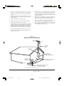
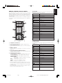
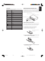
Model PM7200 User Guide
Integrated Amplifier
PM7200U(表1,表2,表4,他)
Page 4
03.12.17, 11:19 AM Adobe PageMaker 6.5J/PPC
CONTENTS
Engligh ............................................................................................................................................................................................. page 1
Figures ........................................................................................................................................................................................... page 35
PM7200U(表1,表2,表4,他)
Page 6
03.12.17, 11:19 AM Adobe PageMaker 6.5J/PPC
CAUTION
RISK OF ELECTRIC SHOCK
DO NOT OPEN
CAUTION: TO REDUCE THE RISK OF ELECTRIC SHOCK,
DO NOT REMOVE COVER (OR BACK)
NO USER-SERVICEABLE PARTS INSIDE
REFER SERVICING TO QUALIFIED SERVICE PERSONNEL
The lightning flash with arrowhead symbol
within an equilateral triangle is intended to
alert the user to the presence of uninsulated
“dangerous voltage” within the product’s
enclosure that may be of sufficient magnitude
to constitute a risk of electric shock to persons.
The exclamation point within an equilateral
triangle is intended to alert the user to the
presence of important operating and
maintenance (servicing) instructions in the
literature accompanying the product.
WARNING
TO REDUCE THE RISK OF FIRE OR ELECTRIC SHOCK,
DO NOT EXPOSE THIS PRODUCT TO RAIN OR MOISTURE.
CAUTION: TO PREVENT ELECTRIC SHOCK, MATCH WIDE
BLADE OF PLUG TO WIDE SLOT, FULLY INSERT.
ATTENTION: POUR ÉVITER LES CHOCS ÉLECTRIQUES,
INTRODUIRE LA LAME LA PLUS LARGE DE LA FICHE DANS LA
BORNE CORRESPONDANTE DE LA PRISE ET POUSSER
JUSQU’AU FOND.
NOTE TO CATV SYSTEM INSTALLER:
This reminder is provided to call the CATV (Cable-TV) system installer’s attention to Section 820-40 of the NEC which provides
guidelines for proper grounding and, in particular, specifies that the cable ground shall be connected to the grounding system of the
building, as close to the point of cable entry as practical.
NOTE:
- Reorient or relocate the receiving antenna.
This equipment has been tested and found to comply with
the limits for a Class B digital device, pursuant to Part 15
of the FCC Rules. These limits are designed to provide
reasonable protection against harmful interference in a
residential installation. This equipment generates, uses
and can radiate radio frequency energy and, if not
installed and used in accordance with the instructions,
may cause harmful interference to radio communications. However, there is no guarantee that interference
will not occur in a particular installation. If this equipment
does cause harmful interference to radio or television
reception, which can be determined by tuning the
equipment off and on, the user is encouraged to try to
correct the interference by one or more of the following
measures:
- Increase the separation between the equipment and receiver.
- Connect the equipment into an outlet on a circuit different
from that to which the receiver is connected.
- Consult the dealer or an experienced radio/TV technician for
help.
NOTE:
Changes or modifications not expressly approved by the
party responsible for compliance could void the user’s
authority to operate the equipment.
i
PM7200U(表1,表2,表4,他)
Page 1
03.12.17, 11:19 AM Adobe PageMaker 6.5J/PPC
IMPORTANT SAFETY
INSTRUCTIONS
READ BEFORE OPERATING EQUIPMENT
This product was designed and manufactured to meet strict quality and
safety standards. There are, however, some installation and operation
precautions which you should be particularly aware of.
1.
Read Instructions – All the safety and operating instructions
should be read before the product is operated.
2.
Retain Instructions – The safety and operating instructions should
be retained for future reference.
3.
Heed Warnings – All warnings on the product and in the operating
instructions should be adhered to.
4.
Follow Instructions – All operating and use instructions should be
followed.
5.
Cleaning – Unplug this product from the wall outlet before
cleaning. Do not use liquid cleaners or aerosol cleaners. Use a
damp cloth for cleaning.
6.
Attachments – Do not use attachments not recommended by the
product manufacturer as they may cause hazards.
7.
Water and Moisture – Do not use this product near water-for
example, near a bath tub, wash bowl, kitchen sink, or laundry tub,
in a wet basement, or near a swimming pool, and the like.
8.
Accessories – Do not place this product on an unstable cart,
stand, tripod, bracket, or table. The product may fall, causing
serious injury to a child or adult, and serious damage to the
product. Use only with a cart, stand, tripod, bracket, or table
recommended by the manufacturer, or sold with the product. Any
mounting of the product should follow the manufacturer’s
instructions, and should use a mounting accessory recommended
by the manufacturer.
9.
10.
11.
12.
Grounding or Polarization – This product may be equipped with a
polarized alternating-current line plug (a plug having one blade
wider than the other). This plug will fit into the power outlet only
one way. This is a safety feature. If you are unable to insert the
plug fully into the outlet, try reversing the plug. If the plug should
still fail to fit, contact your electrician to replace your obsolete
outlet. Do not defeat the safety purpose of the polarized plug.
AC POLARIZED PLUG
13.
Power-Cord Protection – Power-supply cords should be routed so
that they are not likely to be walked on or pinched by items placed
upon or against them, paying particular attention to cords at plugs,
convenience receptacles, and the point where they exit from the
product.
14.
Protective Attachment Plug – The product is equipped with an
attachment plug having overload protection. This is a safety
feature. See Instruction Manual for replacement or resetting of
protective device. If replacement of the plug is required, be sure
the service technician has used a replacement plug specified by
the manufacturer that has the same overload protection as the
original plug.
15.
Outdoor Antenna Grounding – If an outside antenna or cable
system is connected to the product, be sure the antenna or cable
system is grounded so as to provide some protection against
voltage surges and built-up static charges. Article 810 of the
National Electrical Code, ANSI/NFPA 70, provides information
with regard to proper grounding of the mast and supporting
structure, grounding of the lead-in wire to an antenna discharge
unit, size of grounding conductors, location of antenna-discharge
unit, connection to grounding electrodes, and requirements for the
grounding electrode. See Figure 1.
16.
Lightning – For added protection for this product during a lightning
storm, or when it is left unattended and unused for long periods of
time, unplug it from the wall outlet and disconnect the antenna or
cable system. This will prevent damage to the product due to
lightning and power-line surges.
17.
Power Lines – An outside antenna system should not be located
in the vicinity of overhead power lines or other electric light or
power circuits, or where it can fall into such power lines or circuits.
When installing an outside antenna system, extreme care should
be taken to keep from touching such power lines or circuits as
contact with them might be fatal.
18.
Overloading – Do not overload wall outlets, extension cords, or
integral convenience receptacles as this can result in a risk of fire
or electric shock.
19.
Object and Liquid Entry – Never push objects of any kind into this
product through openings as they may touch dangerous voltage
points or short-out parts that could result in a fire or electric shock.
Never spill liquid of any kind on the product.
A product and cart combination should be moved with care. Quick
stops, excessive force, and uneven surfaces may cause the
product and cart combination to overturn.
Ventilation – Slots and openings in the cabinet are provided for
ventilation and to ensure reliable operation of the product and to
protect it from overheating, and these openings must not be
blocked or covered. The openings should never be blocked by
placing the product on a bed, sofa, rug, or other similar surface.
This product should not be placed in a built-in installation such as
a bookcase or rack unless proper ventilation is provided or the
manufacturer’s instructions have been adhered to.
Power Sources – This product should be operated only from the
type of power source indicated on the marking label. If you are not
sure of the type of power supply to your home, consult your
product dealer or local power company. For products intended to
operate from battery power, or other sources, refer to the
operating instructions.
ii
PM7200U(表1,表2,表4,他)
Page 2
03.12.17, 11:19 AM Adobe PageMaker 6.5J/PPC
20.
Servicing – Do not attempt to service this product yourself as
opening or removing covers may expose you to dangerous
voltage or other hazards. Refer all servicing to qualified service
personnel.
21.
Damage Requiring Service – Unplug this product from the wall
outlet and refer servicing to qualified service personnel under the
following conditions:
a.
When the power-supply cord or plug is damaged.
b.
If liquid has been spilled, or objects have fallen into the product.
c.
If the product has been exposed to rain or water.
d.
If the product does not operate normally by following the operating
instructions. Adjust only those controls that are covered by the
operating instructions as an improper adjustment of other controls
may result in damage and will often require extensive work by a
qualified technician to restore the product to its normal operation.
e.
If the product has been dropped or damaged in any way, and
f.
When the product exhibits a distinct change in performance – this
indicates a need for service.
22.
Replacement Parts – When replacement parts are required, be
sure the service technician has used replacement parts specified
by the manufacturer or have the same characteristics as the
original part. Unauthorized substitutions may result in fire, electric
shock, or other hazards.
23.
Safety Check – Upon completion of any service or repairs to this
product, ask the service technician to perform safety checks to
determine that the product is in proper operating condition.
24.
Wall or Ceiling Mounting – The product should be mounted to a
wall or ceiling only as recommended by the manufacturer.
25.
Heat – The product should be situated away from heat sources
such as radiators, heat registers, stoves, or other products
(including amplifiers) that produce heat.
FIGURE 1
EXAMPLE OF ANTENNA GROUNDING AS PER
NATIONAL ELECTRICAL CODE, ANSI/NFPA 70
ANTENNA
LEAD IN
WIRE
GROUND
CLAMP
ANTENNA
DISCHARGE UNIT
(NEC SECTION 810-20)
ELECTRIC
SERVICE
EQUIPMENT
GROUNDING CONDUCTORS
(NEC SECTION 810-21)
GROUND CLAMPS
POWER SERVICE GROUNDING
ELECTRODE SYSTEM
(NEC ART 250, PART H)
NEC - NATIONAL ELECTRICAL CODE
This Class B digital apparatus complies with Canadian ICES-003.
Cet appareil numérique de la Classe B est conforme à la norme
NMB-003 du Canada.
iii
PM7200U(表1,表2,表4,他)
Page 3
03.12.17, 11:19 AM Adobe PageMaker 6.5J/PPC
Figure numbers refer to the illustrations located at the back of this
User’s Manual. Numbers assigned to parts and controllers match
the callout numbers used inside the illustrations.
ALL UPPER-CASE BOLD type indicates the name of a connection
or controller as it is actually marked on the amplifier.
(Figure 1)
ENGLISH
CONNECTIONS
ABOUT THIS USER’S GUIDE
CONNECTING A TUNER
Note the following important precautions whenever operating the
amplifier.
Connect the output jacks of your CD player to the CD jacks of this
amplifier.
SELECTING A LOCATION
CONNECTING A TURNTABLE
Take a few moments to consider the following points before choosing a place for the amplifier.
Connect the L (Left) output cord of the turntable to the “L”PHONO
jack of this amplifier, and the R (Right) output cord to the “R”PHONO
jack. If the turntable has a ground wire, make sure you connect it to
the GND terminal of this amplifier. The GND terminal does not need
to be connected if the turntable does not have a ground wire.
— Make sure ventilation holes are not blocked or covered.
— Ensure that air can circulate freely around the amplifier.
— Locate the amplifier on a surface that is free of vibration.
CONNECTING A TAPE DECK
— Choose a place where the amplifier will not be exposed to interference from an external source.
Connect the IN (recording input) jacks of the tape recorder to the
TAPE OUT jack of this amplifier, and the OUT (playback output)
jacks of the tape recorder to the TAPE IN jack.
— Avoid excessive heat, cold, moisture, and dust.
— Keep the amplifier out of direct sunlight.
CONNECTING A PROCESSOR
— Do not locate the amplifier where it will be exposed to electrostatic charge.
Connect the IN jacks of the processor to the PROCESSOR OUT
jack of this amplifier, and the OUT jacks of the processor to the
PROCESSOR IN jack. When not used, leave these jacks connected
with the supplied connecting pins.
GENERAL SAFETY PRECAUTIONS
— Never place heavy objects on top of the amplifier.
CONNECTING A SPEAKER SYSTEM
— Should foreign matter or water get into the interior of the amplifier, immediately turn it off and contact your original dealer or
Marantz service provider.
You amplifier has two sets of SPEAKER SYSTEM terminals, which
means you can connect either one or two speaker systems.
— Never pull on the mains lead when unplugging the amplifier.
Grasp the plug itself.
DEUTSCH
CONNECTING A COMPACT DISC PLAYER
NEDERLANDS
PRECAUTIONS
FRANÇAIS
Connect the output jacks of your stereo tuner to the TUNER jacks of
this amplifier.
Connecting One Speaker System
Note the following points when connecting a single speaker system.
— The impedance of each speaker should be between 8 and 16
ohms. Connecting a speaker with impedance less than 8 ohms
can causes activation of the amplifier’s protection circuitry during play, making normal stereo playback impossible.
— Connect the right channel speaker to the amplifier’s R terminals, and the left channel speaker to the L terminals.
— The output terminals have positive (+: red) and negative (–: black)
polarity. Each speaker must also have the same polarity (+/–).
Be sure to match the polarity of the amplifier with that of the
speakers (+ with +, – with –) when making connections.
•
Connecting Two Speaker Systems
DANSK
SVENSKA
Make sure that the impedance of each speaker is at least 16 ohms.
Connecting a speaker with impedance less than 16 ohms can causes
activation of the amplifier’s protection circuitry during play, making
normal stereo playback impossible.
PORTUGUÊS
•
ITALIANO
Turn the kobes on the speaker terminals by hand. (Do not use a
tool to turn the knobs.)
— It is always a good idea to disconnect the amplifier from the
mains supply whenever leaving it unattended for long periods
or during thunderstorms.
ESPAÑOL
NOTE:
1
PM7200U(ENG)
Page 1
03.12.17, 11:18 AM Adobe PageMaker 6.5J/PPC
FRANÇAIS
ENGLISH
CONTROLS, CONNECTORS,
!3 CLASS A INDICATOR
AND INDICATORS
This indicator lights when the amplifier is in the Class A operation
mode. See “@3 Class A Switch” for details.
(Figure 2)
!4 TAPE,CD-R/MD SELECTOR BUTTONS
Press one of these switches to select a connected tape deck or
CD-R/MD for monitoring or playback. Pressing a TAPE,CD-R/MD
SELECTOR button causes the indicator above it to light.
Pressing a TAPE,CD-R/MD SELECTOR button while the amplifier
is in the Standby Mode automatically turns power back on.
q REMOTE CONTROL BUS TERMINALS (REMOTE
CONT. BUS)
These terminals can used to connect other audio equipment that is
equipped with a remote control bus terminal. Connection requires a
special cable. The bus OUT terminal sends signal to the connected
equipment, while the bus IN terminals receive signals.
!5 INPUT SELECTOR
Use this selector to specify PHONO, CD, TUNER, AUX 1, or AUX 2
as the program source for recording or play. Selecting a program
source causes the indicator above it to light.
Changing the INPUT SELECTOR setting while the amplifier is in
the Standby Mode automatically turns power back on.
These auxiliary input jacks can be used to connect the audio output
of a TV multiplex/stereo audio tuner, VCR, laserdisc system, or other
AV component audio output.
!6 REMOTE SENSOR
e TUNER INPUT JACKS
The remote sensor receive infrared commands from the remote control unit. Note that the remote control unit must be pointed directly
at the remote sensor for proper operation.
Connect these jacks to the output jacks of your tuner.
r CD INPUT JACKS
Connect these jacks to the output jacks of your compact disc player.
!7 VOLUME CONTROL
t PHONO INPUT JACKS
Rotate this knob clockwise to increase volume, and counter-clockwise to decrease volume.
Connect these jacks to the output jacks of your turntable. These
input jacks are exclusive for a turntable equipped with MM (Moving
Magnet) cartridge.
!8 MUTING INDICATOR
This indicator lights when muting is activated by pressing the remote
control unit’s MUTE button.
y TAPE, CD-R/MD IN/OUT JACKS
IMPORTANT:
Connect these jacks to the play (output) and record (input) jacks of
your recorders. Up to two decks can be connected.
Be sure to double check the VOLUME control setting before press
ing the remote control unit’s MUTE button to cancel muting.
Restoring audio output while the VOLUME control setting is too
high can damage your speakers.
u PROCESSOR IN/OUT JACKS
Use these jacks to connect a graphic equalizer or other analog audio
processor. When not used, leave these jacks connected with the
supplied connecting pins.
!9 BALANCE CONTROL
If your turntable has a grounding wire, connect it to this terminal.
Rotate this knob to shift the balance of stereo output left and right.
Note that turning the BALANCE control all the way in either direction
causes output from the other side to be eliminated entirely.
o SPEAKER SYSTEMS
@0 RECORD (REC) SELECTOR SWITCH
Connect your speaker system(s) to these terminals. There are two
sets of terminals, so you can connect either one or two speaker
systems.
Use this switch to select recording between the tape deck and CDR/MD or recording of the signal selected by the INPUT SELECTOR
SWITCH and out put from the REC OUT jacks.
See the note under “Tape Deck, CD-R/MD Operation” on page 4 for
full details about settings.
i GROUND TERMINAL
!0 AC OUTLETS (SWITCHED)
Connect the power cord of another piece of equipment (VCR, tuner,
CD) when you want the power of the connected equipment automatically turned on whenever you turn on this amplifier. For this to
work correctly, the power switch of the connected equipment must
be left on. Normally, the audio output of the connected equipment
is also connected to this amplifier. Note that the total power consumption of the connected all equipment must not exceed 120W.
@1 SOURCE DIRECT SWITCH
Press this switch to turn SOURCE DIRECT on (depressed) and off
(raised).
When SOURCE DIRECT is turned on, the audio signal path is as
short and direct as possible in order to enjoy high-quality sources
under the best conditions possible.
!1 POWER CORD
NOTE:
Tape and CD-R/MD playback and recording are not possible when
the SOURCE DIRECT switch is on. The TONE and BALANCE
controls are also disabled. Any graphic equalizer or other such
component that is connected to the PROCESSOR IN/OUT jacks
will not have any effect. In order to use any of these components
or controls, it is necessary to turn the SOURCE DIRECT switch off.
Connect the power cord to a standard household power outlet.
!2 POWER SWITCH
Press this switch to turn power on (depressed) and off (raised). Note
that the power of any equipment connected to the switched AC outlet
on the rear panel (see !0 above) is also turned on and off by operating this switch.
Turning on the power causes the POWER indicator to light, and the
POWER indicator goes out when power is turned off.
While the POWER switch is in the ON position (depressed), you
can put use the remote control unit’s SYSTEM POWER ON and
OFF button to switch the amplifier between standby (indicated when
the @6 STANDBY indicator is lit) and power on.
@2 BASS AND TREBLE TONE CONTROLS
Use these controls to control the levels of their corresponding frequency bands. TREBLE adjusts the high frequency band, while
BASS adjusts the low frequency band. Rotating a control towards
(+) enhance the frequency band, while rotating towards (–)
attenuates the frequency band.
DANSK
SVENSKA
PORTUGUÊS
ITALIANO
ESPAÑOL
NEDERLANDS
DEUTSCH
w AUX1/AUX2 INPUT JACKS
2
PM7200U(ENG)
Page 2
03.12.17, 11:18 AM Adobe PageMaker 6.5J/PPC
OPERATION
1
Press this switch while amplifier power is turned off to switch between Class A (25W, 8 ohms) and Class AB (95W, 8 ohms) amplifier
operation. The CLASS A indicator is lit while Class A operation is
selected, and Class AB operation is indicated when the CLASS A
indicator is not lit.
ENGLISH
@3 CLASS A SWITCH
3
INTEGRATED AMPLIFIER PM7200
INPUT SELECTOR
VOLUME
PHONO
CD
TUNER
TAPE
AUX1
AUX2
CD-R/MD
MUTE
CD-R/MD
BASS
TREBLE
IMPORTANT:
MIN
REC SELECTOR
The top cover may become hot during Class A operation, but this
does not indicate malfunction. Note, however, that you should never
place anything on top of this amplifier. Doing so can block ventilation holes, resulting a build up of heat and malfunction of or damage to the amplifier.
POWER ON/OFF
PHONES
STANDBY
1
SPEAKERS
2
OFF
SOURCE
TAPE
MAX
BALANCE
CLASS A
CD-R
SOURCE DIRECT
CD-R TAPE
COPY
ON
OFF
-
+
-
+
ON
OFF
ON
OFF
L
R
3
@4 SPEAKER SWITCHES 1/2
FRANÇAIS
TAPE
@5 PHONES JACK
TO PLAY AN ANALOG RECORD
Use the jack to plug in headphones that are equipped with a
standard phone jack.
1. Set INPUT SELECTOR to PHONO.
DEUTSCH
Perform the applicable operation on the connected
equipment.
Use these switches to turn speaker output on (depressed) and off
(raised). You can turn off speaker output when listening to output
over headphones.
NOTE:
•
Be sure the set VOLUME to is minimum setting before placing
the stylus onto the record or before replacing the turntable’s cartridge.
•
Never subject the turntable to shock or vibration while a record
is playing. This can cause the stylus to jump and possible
damage the record.
•
Locating your turntable too close to the speakers can cause howling, which will make it impossible to use higher volume settings.
•
Never turn off power while the stylus is in contact with the surface
of the record.
TO LISTEN TO AN FM/AM BROADCAST
ESPAÑOL
3. Use VOLUME to adjust volume, and BASS and TREBLE to adjust the tone.
This indicator is lit while the amplifier is in the Standby Mode. Pressing the remote control unit’s POWER buttons switches the amplifier
between standby and power on.
NEDERLANDS
2. Play the record on the turntable.
@6 STANDBY INDICATOR
1. Set INPUT SELECTOR to TUNER.
3. Use VOLUME to adjust volume, and BASS and TREBLE to adjust the tone.
TO PLAY A COMPACT DISC
1. Set INPUT SELECTOR to CD.
ITALIANO
2. Tune in the desired station on the tuner.
2. Play a CD on the CD player.
TO PLAY EQUIPMENT CONNECTED TO THE AUX 1 OR
AUX 2 JACKS
1. Set INPUT SELECTOR to AUX1 or AUX2.
2. Set up the connected equipment for play.
DANSK
SVENSKA
3. Use VOLUME to adjust volume, and BASS and TREBLE to adjust the tone.
PORTUGUÊS
3. Use VOLUME to adjust volume, and BASS and TREBLE to adjust the tone.
3
PM7200U(ENG)
Page 3
03.12.17, 11:18 AM Adobe PageMaker 6.5J/PPC
ENGLISH
TAPE DECK, CD-R/MD OPERATION
USING THE REC SELECTOR
Use the REC SELECTOR E to specify the type of recording you
want to perform.
1. The OFF setting cuts off all signal output from the REC OUT
jacks. Note that REC SELECTOR Eshould normally be in the
OFF setting except when you are recording to tape. The OFF
setting shortens the signal path within the amplifier, which
minimizes crosstalk and other factors that can cause deterioration of the sound.
INTEGRATED AMPLIFIER PM7200
INPUT SELECTOR
VOLUME
TAPE
PHONO
TUNER
CD
DEUTSCH
FRANÇAIS
TAPE
AUX1
AUX2
CD-R/MD
MUTE
CD-R/MD
BASS
TREBLE
MIN
REC SELECTOR
POWER ON/OFF
PHONES
STANDBY
1
SPEAKERS
2
OFF
SOURCE
TAPE
MAX
BALANCE
CLASS A
CD-R
SOURCE DIRECT
CD-R TAPE
COPY
ON
OFF
-
+
-
+
ON
OFF
ON
OFF
L
R
2. SOURCE sets up for recording the signal from the source selected by INPUT SELECTOR C.
3. COPY sets up for recording from TAPE to CD-R, or from CD-R
to TAPE. You can listen to the output from another source while
recording in the COPY position by selecting the source you want
with INPUT SELECTOR C.
Perform the applicable operation on the connected tape
deck.
TO PLAY BACK FROM A TAPE OR CD-R/MD
1. Press TAPE or CD-R/MD A to the indicator above the switch is lit.
2. Play a tape on the tape deck or CD-R/MD disc.
3. Use VOLUME B to adjust volume.
ESPAÑOL
NEDERLANDS
4. Use BASS and TREBLE D to adjust the tone.
NOTE:
You can play back from a tape regardless of the INPUT SELECTOR C setting.
TO RECORD TO A TAPE OR CD-R/MD
1. Set INPUT SELECTOR C to PHONO, CD, TUNER, AUX 1, or
AUX 2 to select the source you want to record from.
2. Use the REC SELECTOR E to specify the type of recording
you want to perform.
3. Start play on the selected source.
4. Perform the applicable operation on the connected tape deck
to record the output from the selected source.
NOTE:
DANSK
SVENSKA
PORTUGUÊS
ITALIANO
The SOURCE DIRECT switch must be turned off (raised) in order
to record to a tape deck. Recording will not possible when
SOURCE DIRECT is turned on (depressed).
4
PM7200U(ENG)
Page 4
03.12.17, 11:18 AM Adobe PageMaker 6.5J/PPC
CD BUTTON
The RC8000PM remote control unit can be used to control any
Marantz AV equipment that has a remote sensor, as well as other
Marantz equipment connected to the main equipment’s remote
control bus. The buttons of the remote control unit are arranged on
the control panel according to functional groups as shown in the
illustration below.
See the relevant user manuals for details on combination equipment
as operation content may differ depending on the equipment
combined.
The following are the functions assigned to control buttons after the
CD amplifier source button is pressed.
BUTTON NAME
FUNCTION
None
Pause
SYSTEM POWER SOURCE
ON
OFF ON/OFF AMP
TUNER CD-R
AUX1
AUX2
TAPE
MD
1
2
3
A, F/P
4
5
6
B, - / - -
7
–
8
9
0
+
MODE
MEMO
Open/Close
+
Next Track
–
Previous Track
A, F/P
Disc Select down
B, –/––
Disc Select up
MODE
Auto Music Scan (AMS)
MEMO
Store
TEXT (MODE 1)
Text
TIME (MODE 2)
Time
Next Track
1–MODE–2
SCROLL CANCEL TEXT TIME
Previous Track
MUTE
OPEN/
CLOSE
SCROLL
Scroll
CANCEL
Cancel
VOLUME
RC8000PM
SYSTEM REMOTE CONTROLLER
TUNER BUTTON
The following are the functions assigned to control buttons after the
TUNER amplifier source button is pressed.
z Amplifier Source Buttons*
ESPAÑOL
CD
OPEN/CLOSE
DEUTSCH
Fast-reverse
NEDERLANDS
Fast-forward
FRANÇAIS
Play
Stop
PHONO
ENGLISH
REMOTE CONTROL UNIT RC 8000PM
Use these buttons to select the amplifier’s program source.
BUTTON NAME
Use these buttons to control operation of a VCR, CD player,
etc.
None
Tuning up
c Numeric Key Pad
Tuning down
Use these buttons to input buttons for control of a tuner, CD
player, etc.
None
v Player/Tuner Auxiliary Operation Buttons
None
Use these buttons to control the mode switching and track jump
operations of a tuner, CD, etc.
Pressing an amplifier source button in group z to select a source
causes the buttons in groups x, c and v to take on functions
to control the selected source equipment (except for PHONO
and AMP button).
The following tables shows the functions of buttons in these
groups for each available amplifier source.
None
+
Preset up
–
Preset down
A, F/P
Channel/Frequency/Preset
B, –/––
1/2/3 Digits
MODE
Stereo/Mono
MEMO
Store
TEXT (MODE 1)
None
TIME (MODE 2)
None
None
None
Display
CANCEL
Cancel
DANSK
SCROLL
SVENSKA
Use these buttons to control power on/Standby, volume level, etc.
SYSTEM POWER ON : Power supply is ON for the Unit.
SYSTEM POWER OFF : Power supply is OFF for the Unit.
SOURCE ON/OFF :
Power supply is ON/OFF for equipment selected by
the z button.
MUTE
: Mutes amp(this equipment’s) sound.
VOL
: Increases this equipment’s volume.
VOL
: Decreases this equipment’s volume.
OPEN/CLOSE
PORTUGUÊS
None
b Amplifier Operation Buttons
*
FUNCTION
ITALIANO
x Player Operation Buttons
5
PM7200U(ENG)
Page 5
03.12.17, 11:18 AM Adobe PageMaker 6.5J/PPC
ENGLISH
CD-R BUTTON
AUX 2 BUTTON
The following are the functions assigned to control buttons after the
CD-R amplifier source button is pressed.
The following are the functions assigned to control buttons after the
AUX 2 amplifier source button is pressed.
ESPAÑOL
NEDERLANDS
DEUTSCH
FRANÇAIS
BUTTON NAME
FUNCTION
VCR Play
Fast-forward
VCR Fast-forward
Fast-reverse
VCR Rewind
None
None
Stop
VCR Stop
VCR Pause
OPEN/CLOSE
Open/Close
OPEN/CLOSE
Tape Eject
+
Next track
+
Step up
–
Previous track
–
Step down
A, F/P
None
A, F/P
Channel/Preset
B, –/––
None
B, –/––
1/2/3 Digits
MODE
Auto Music Scan (AMS)
MODE
Sound Select
MEMO
Store
MEMO
Store (Memo Rew.)
TEXT (MODE 1)
Text
TEXT (MODE 1)
Text ↔ TV Station
TIME (MODE 2)
Time
TIME (MODE 2)
Scroll Display (Time)
Next track
VCR Fast Run FWD
Previous track
VCR Fast Run REV
SCROLL
Scroll
SCROLL
None
CANCEL
Cancel
CANCEL
None
AUX 1 BUTTON
TAPE BUTTON
The following are the functions assigned to control buttons after the
AUX 1 amplifier source button is pressed.
The following are the functions assigned to control buttons after the
TAPE amplifier source button is pressed.
ITALIANO
PORTUGUÊS
BUTTON NAME
Pause
BUTTON NAME
FUNCTION
BUTTON NAME
FUNCTION
VCR Play
Play
VCR Fast-forward
Fast-forward
VCR Rewind
Rewind
None
Direction Switch
VCR Stop
Stop
VCR Pause
Pause
OPEN/CLOSE
Tape Eject
OPEN/CLOSE
Eject
+
Channel/Program up
+
Next
–
Channel/Program down
–
Previous
A, F/P
Channel/Frequency/Preset
A, F/P
Deck A
B, –/––
1/2/3 Digits
B, –/––
Deck B
MODE
Sound Select
MODE
Auto Music Scan (AMS)
MEMO
Store
MEMO
Store
TEXT (MODE 1)
TV Station ↔ Text
TEXT (MODE 1)
Scroll Display (Text)
TIME (MODE 2)
Scroll Display (Time)
TIME (MODE 2)
Scroll Display (Time)
VCR Fast Run FWD
Next
VCR Fast Run REV
Previous
SCROLL
None
SCROLL
None
CANCEL
None
CANCEL
Cancel
DANSK
SVENSKA
FUNCTION
Play
6
PM7200U(ENG)
Page 6
03.12.17, 11:18 AM Adobe PageMaker 6.5J/PPC
When operating the remote control unit (RC8000PM), point its transmitter directly at the remote sensor, which is located on the front of
the amplifier. Make sure the remote control unit is no further than
about 5 meters from the remote sensor. Remote control operation
may not be possible if the remote control unit’s transmitter is not
pointing directly at the remote sensor, or if there is an obstruction
between the transmitter and sensor.
FUNCTION
Play
Fast-forward
Rewind
Remote Control Operating Range
None
Stop
Amplifier (PM7200)
Pause
Eject
+
Next
–
Previous
A, F/P
Edit
B, –/––
Enter
MODE
Monitor
MEMO
Store
TEXT (MODE 1)
None
TIME (MODE 2)
Time
Approximately 5 meters
60°
Remote Control Unit RC8000PM
REMOTE CONTROL UNIT BATTERIES
Remote control unit batteries should last for about one year under
normal conditions. Replace batteries as soon as possible whenever
they show signs of running low. Also, be sure to remove the batteries
if you do not plan to use the remote control unit for a long time.
Next
Previous
SCROLL
Scroll
CANCEL
Delete
DEUTSCH
OPEN/CLOSE
NEDERLANDS
BUTTON NAME
ENGLISH
USING THE REMOTE CONTROL UNIT
The following are the functions assigned to control buttons after the
MD amplifier source button is pressed.
FRANÇAIS
MD BUTTON
Back of Remote Control Unit
(RC8000PM)
(2) Load two batteries, making sure their positive (+) and
negative (–) ends are facing correctly.
ITALIANO
(1) Remove the battery compartment cover.
ESPAÑOL
TO LOAD REMOTE CONTROL UNIT BATTERIES
DANSK
(3) Slide the battery compartment cover back into place and
press until it clicks shut.
SVENSKA
PORTUGUÊS
Two AA-size (R6) (UM-3) batteries
7
PM7200U(ENG)
Page 7
03.12.17, 11:18 AM Adobe PageMaker 6.5J/PPC
FRANÇAIS
ENGLISH
CARE AND MAINTENANCE
TROUBLESHOOTING
This section describes care and maintenance that you must perform in order to make sure your Marantz amplifier performs at the
level for which it is designed. Be sure to unplug the amplifier from
the mains supply before any care and maintenance.
Whenever you have a problem with the amplifier, check the following points before requesting service. What may seem to be a serious
malfunction is often the result of a simple operational error. If you
still have problems, contact your original dealer or write directly to
your nearest service provider as listed on the Marantz Authorised
Service Station list.
NORMAL CLEANING
The exterior of your amplifier will last indefinitely with proper care
and cleaning. For normal cleaning, wipe exterior surfaces with a
soft, lint-free cloth.
The amplifier does not operate and indicators do not light.
IMPORTANT:
Indicators light, but the amplifier does not operate.
Any of the following will mar the finish of your amplifier and should
never be used for cleaning.
1. Check the SELECTOR and VOLUME settings.
1. Check to see if the power cord is correctly inserted into a power
outlet.
2. Check to see if the supplied connecting pins are correctly inserted into the PROCESSOR IN/OUT jacks.
NEDERLANDS
DEUTSCH
— Scouring pads, steel wool, abrasive powders
— Harsh chemical agents (such as a lye solution)
Sound is being produced by only one speaker.
— Alcohol, thinners, benzine, insecticide, or other volatile agents.
1. Check the BALANCE setting.
SPECIAL CLEANING
2. Turn off the amplifier and switch the connections of the left and
right speaker cords. If the same speaker still does not produce
sound, it probably means that the connection cord or the speaker
itself is defective.
Should it amplifier ever become so soiled that normally cleaning is
not enough, use the following procedure for cleaning.
1. Prepare a cleaning solution of one part mild neutral liquid detergent and six parts water.
Considerable humming is produced when playing from a
turntable.
2. Moisten a soft, lint-free cloth in the cleaning solution and then
wring out all excess moisture from the cloth.
1. Check to see if the plugs from the turntable are properly connected to the amplifier’s PHONO jacks.
3. Wipe off the amplifier with the damp cloth.
2. Connect the turntable’s ground wire to the GND terminal on the
rear panel of the amplifier. If the ground wire is already
connected, try disconnecting it.
4. Dry the amplifier by wiping it with a soft dry cloth.
3. Check to make sure that the turntable’s phono cartridge is securely attached to the tone arm.
Cannot perform remote operation.
Only the most competent and qualified serviced technicians should
be allowed to service this amplifier. Marantz and its factory-trained
warranty personnel have the special knowledge and facilities required for the repair and calibration of this amplifier. After expiration of the warranty period, repairs can be performed for a separate
charge.
Whenever you experience problems, first try to solve the problem
yourself using the troubleshooting procedures provided on this page.
If this does not work, contact your original dealer or write directly to
your nearest service provider as listed on the Marantz Authorised
Service Station list. When you write, be sure to include the model
and serial number of your amplifier, together with a detailed
description of the problem.
1. Make sure the remote control unit’s (RC8000PM) transmitter is
pointed directly as the amplifier’s remote sensor when you perform a remote control unit operation.
2. Check for obstructions between the remote control unit’s transmitter and the amplifier’s remote sensor.
3. Check the batteries of the remote control unit.
4. Make sure there is no strong light (from a window or other source)
shining on the amplifier’s remote sensor.
5. Check to see if there is an RCA cord connected to the REMOTE
CONTROL IN jack on the amplifier’s rear panel.
DANSK
SVENSKA
PORTUGUÊS
ITALIANO
ESPAÑOL
REPAIRS
8
PM7200U(ENG)
Page 8
03.12.17, 11:18 AM Adobe PageMaker 6.5J/PPC
MODEL PM7200 TECHNICAL SPECIFICATIONS
Power output (class AB operation)
RMS 8 ohms (20 Hz-20 kHz) .......................................................................................................... 95 W
DIN 8 ohms .................................................................................................................................... 105 W
THD at 8 ohms RMS rated output ................................................................................................ 0.03%
Damping factor ................................................................................................................................... 150
Power output (classA operation)
RMS 8 ohms (20 Hz-20 kHz) .......................................................................................................... 25 W
DIN 8 ohms ...................................................................................................................................... 28 W
THD at 8 ohms RMS rated output ............................................................................................... 0.03 %
Damping factor ................................................................................................................................... 150
IHF dynamic power (class AB operation)
8 ohms ............................................................................................................................................ 120 W
IHF dynamic power (classA operation)
8 ohms .............................................................................................................................................. 35 W
Magnetic cartridge input
Input sensitivity impedance ......................................................................................... 2.5 mV/47 kOhm
Accuracy of frequency response to IEC RIAA ............................................................................. 0.5 dB
Signal to noise ratio ........................................................................................................................ 85 dB
Tuner/CD/Aux/Tape inputs
Input sensitivity impedance ........................................................................................ 150 mV/40 kOhm
Signal to noise ratio ........................................................................................................................ 88 dB
Frequency response (–1 dB limits, Source Direct) ........................................................ 10 Hz - 50 kHz
Tone characteristic (100 Hz and 10 kHz) ...................................................................................... ±8 dB
Channel separation (1 kHz/10 kHz, Source direct) ........................................................... > 80/> 70 dB
General
Power Requirements ........................................................................................................... 120V, 60 Hz
Dimensions
Width ...................................................................................................................................... 440 mm
Height ..................................................................................................................................... 159 mm
Depth .................................................................................................................................. 374.5 mm
Weight
Unit alone ............................................................................................................................... 12.3 kg
Specifications subject to change without prior notice.
27
Dimensions
20
327.5
374.5
[mm]
440
INTEGRATED AMPLIFIER PM7200
INPUT SELECTOR
VOLUME
PHONO
TUNER
CD
AUX1
AUX2
CD-R/MD
MUTE
CD-R/MD
MIN
REC SELECTOR
BASS
MAX
TREBLE
BALANCE
OFF
POWER ON/OFF
PHONES
STANDBY
1
SPEAKERS
2
SOURCE
TAPE
CLASS A
CD-R
SOURCE DIRECT
CD-R TAPE
146
159
TAPE
TAPE
COPY
OFF
-
+
-
+
ON
OFF
ON
OFF
L
R
13
ON
33
PM7200(SPEC, ILLUST)
Page 33
03.12.17, 11:20 AM Adobe PageMaker 6.5J/PPC
34
PM7200(SPEC, ILLUST)
Page 34
03.12.17, 11:20 AM Adobe PageMaker 6.5J/PPC
Tape Deck
Processor
Input
Output
Output
Input
Tuner
PROCESSOR
SPEAKER SYSTEMS
IN
IN
SYSTEM 1
:
SYSTEM 2
:
SYSTEM 1 AND 2 :
CD-R/MD
MINIMUM 8 OHMS
MINIMUM 8 OHMS
MINIMUM 16 OHMS
OUT
OUT
R
SYSTEM 2
L
R
SYSTEM 1
L
IN
AUX2
TAPE
OUT
AUX1
TUNER
R
L
CD
R
L
PHONO
Output
CD player
Turntable
NOTE:
Turn the knobs on the speaker terminals by hand.
(Do not use a tool to turn the knobs.)
R
SYSTEM 2
L
R
SYSTEM 1
L
5 mm
Loosen the terminal
Insert the core
Tighten the terminal
Connection of speaker cable
Figure 1
35
PM7200(SPEC, ILLUST)
Page 35
03.12.17, 11:20 AM Adobe PageMaker 6.5J/PPC
PROCESSOR
IN
SPEAKER SYSTEMS
SYSTEM 1
: MINIMUM 8 OHMS
SYSTEM 2
: MINIMUM 8 OHMS
SYSTEM 1 AND 2 : MINIMUM 16 OHMS
IN
CD-R/MD
OUT
OUT
+
IN
TAPE
OUT
AUX2
AUX1
TUNER
R
Ð SYSTEM 2 Ð
R
L
+
AC OUTLETS
AC 120V∼60HZ
SWITCHED 1.0A 120W
MAX TOTAL
L
REMOTE
CONTROL
CD
R
+
L
Ð SYSTEM 1 Ð
R
L
IN
+
OUT
PHONO
INTEGRATED AMPLIFIER PM7200
INPUT SELECTOR
VOLUME
TAPE
PHONO
CD
TUNER
TAPE
AUX1
AUX2
CD-R/MD
MUTE
CD-R/MD
MIN
REC SELECTOR
POWER ON/OFF
PHONES
STANDBY
1 SPEAKERS
2
TREBLE
BASS
OFF
SOURCE
MAX
BALANCE
CLASS A
TAPE CD-R
SOURCE DIRECT
CD-R TAPE
COPY
ON
OFF
-
+
-
+
ON
OFF
ON
OFF
L
R
Figure 2
36
PM7200(SPEC, ILLUST)
Page 36
03.12.17, 11:21 AM Adobe PageMaker 6.5J/PPC
www.marantz.com
You can find your nearest authorized distributor or dealer on our website.
JAPAN
Marantz Japan, Inc.
35-1 Sagami Ohno 7-Chome, Sagamihara-shi, Kanagawa 228-8505, Japan
U.S.A.
Marantz America, Inc.
1100 Maplewood Drive, Itasca, IL 60143, U.S.A.
EUROPE
Marantz Europe B.V.
P.O. Box 8744, 5605 LS Eindhoven, The Netherlands
is a registered trademark.
Printed in China
PM7200U(表1,表2,表4,他)
2003/12
Page 5
MITf
03.12.17, 11:19 AM Adobe PageMaker 6.5J/PPC
20AW851250