1
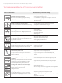
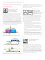
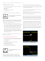
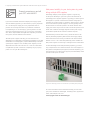
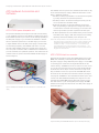
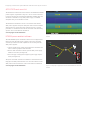
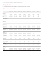
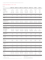
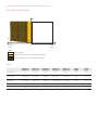
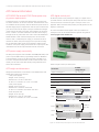
Keysight Technologies
Advanced Power System
N6900 and N7900 Series Power Supplies
02 | Keysight | Advanced Power System N6900 and N7900 Series Power Supplies – Brochure
Advanced Power System (APS) Overview
Overcome your power test challenges with the
Advanced Power System family
With the Keysight Technologies, Advanced Power System (APS)
1 kW and 2 kW system power supplies, you get a new level of
power supply performance. The Advanced Power System (APS)
family was designed with VersaPower architecture to help you
overcome your toughest power test challenges by delivering
industry-leading specifications and innovative features in an
integrated solution for today’s advanced ATE power testing
needs.
VersaPower architecture delivers the fastest, most accurate,
integrated power system
– Accelerate test-system throughput with
industry-leading speed
– Capture your DUT’s current profile with
accurate measurements
– Reduce your ATE development time and cost
with highly integrated capabilities
Get lots of power in a small test-system footprint
Two power ranges deliver a large amount of power in a small
test-system footprint:
– 1 kW models have a 1U full-rack footprint
– 2 kW models have a 2U full-rack footprint
– Both power ranges have built-in paralleling capability up to
10 kW
1000 W in 1U
2000 W in 2U
Choose the right APS performance class to meet your needs
Keysight N6900 Series
DC power supplies
Designed for ATE applications where high performance is critical.
Add performance options to get the dynamic test capabilities of the N7900.
Keysight N7900 Series
dynamic DC power supplies
Designed for ATE applications where high-speed dynamic sourcing and measurement is needed
Choose the APS model with the voltage and current you need
Both the N6900 Series DC power supplies and the N7900 Series dynamic DC power supplies provide five voltage and current
combinations at the 1 kW power range and seven voltage and current combinations at the 2 kW power range.
Keysight N6900 Series DC power supplies
Keysight N7900 Series dynamic DC power supplies
1 kW models
2 kW models
1 kW models
2 kW models
N6950A 9 V, 100 A
N6970A 9 V, 200 A
N7950A 9 V, 100 A
N7970A 9 V, 200 A
N6951A 20 V, 50 A
N6971A 20 V, 100 A
N7951A 20 V, 50 A
N7971A 20 V, 100 A
N6952A 40 V, 25 A
N6972A 40 V, 50 A
N7952A 40 V, 25 A
N7972A 40 V, 50 A
N6953A 60 V, 16.7 A
N6973A 60 V, 33 A
N7953A 60 V, 16.7 A
N7973A 60 V, 33 A
N6954A 80 V, 12.5 A
N6974A 80 V, 25 A
N7954A 80 V, 12.5 A
N7974A 80 V, 25 A
N6976A 120 V, 16.7 A
N7976A 120 V, 16.7 A
N6977A 160 V, 12.5 A
N7977A 160 V, 12.5 A
03 | Keysight | Advanced Power System N6900 and N7900 Series Power Supplies – Brochure
Test challenges and how the APS helps you overcome them
The APS, with Keysight’s exclusive VersaPower architecture, helps you overcome a wide variety of power test challenges.
Power related test challenge
Increasing test system throughput
Reducing test time can mean big savings, so achieving
throughput gains is a never-ending quest.
How the APS helps you overcome the challenge
– Fast up and down programming speeds (up to 500 µs)
– Fast command processing (< 2 ms)
– List capability to step through a list of voltage or current levels
– Seamless ranging capability for fast current measurements without
sacrificing accuracy
Building a continuous source and load
You need a continuous source and load solution for testing
power storage DUTs.
– Full two-quadrant glitch-free operation across quadrants
– Voltage and current limit settings to keep your
device within its operating range
Protecting against power related damage
When testing expensive DUTs, designing protection from
power damage in the test system is critical.
– Smart triggering
– Fast output response
– Output disconnect relays
– Watchdog timer
Characterizing dynamic current profiles
Your DUT has a current profile with a large dynamic range
that you need to characterize.
– 18-bit high resolution current digitizer
– Adjustable measurement sample rate
– External logging capability
– Peak triggering and measurements
Generating power transients
In harsh real-world environments, DUTs can face power
transients, such as surges and interrupts. To ensure proper
operation of a design in the real world, these transients
need to be simulated in testing.
– AWG capability
– Step function capability
– High bandwidth mode
Characterizing inrush current
You need to capture the large current surge that occurs
when you first turn on power to your DUT with reactive
elements at the input.
– High resolution current and voltage digitizers
– Pre- and post-triggering for capturing measurement data
– Large current range that is over 2x the rated output of the power
supply
Maintaining output integrity under dynamic load
conditions
Maintaining a stable output voltage free of oscillations and
voltage droop can be a challenge under a very dynamic
load, especially when working with long cable runs.
– Fast transient response to ensure minimal voltage droop to load
transients
– High and low output bandwidth settings for tuning the output to
your load
Tracking power events for root-cause analysis
You want to track power events during root-cause analysis
testing to see why or if you’re DUT was
damaged during test.
– Built-in Black Box Recorder
– Records voltage, current, power, trigger events, mode changes, and
more in non-volatile memory
Properly powering on/off a DUT
To prevent damage at turn-on or turn-off, you need to
properly sequence multiple supplies on/off or tune their
slew rates.
– Sequencing capability across multiple APS supplies
– Sequencing capability with Keysight’s N6700 modular power supply
family
– Adjustable slew rate control
04 | Keysight | Advanced Power System N6900 and N7900 Series Power Supplies – Brochure
A Deeper Look at How the APS Can Help You Overcome Your Power Test Challenges
Accelerate test throughput
with industry-leading specifications
25
Current
20
Accurately characterize your DUT’s power
profile with advanced
measurements
The APS provides simultaneous voltage and current
measurement capabilities that deliver high accuracy and
resolution. Make measurements using two main modes:
averaged or digitized. In average mode, the APS delivers highaccuracy DMM-quality voltage and current measurements.
The digitizing capability allows you to capture dynamic
current or voltage profiles at much higher resolution than an
oscilloscope.
– Capture inrush current: APS provides an 18-bit current digitizer with
a sample rate up to 200 kS/s, level triggers, and a current measurement range that is 2.25x as high as the max output current range of
the power supply.
–– Accurately capture dynamic current profiles: APS has two currentmeasurement ranges that allow it to measure micro-amps to amps.
The APS uses seamless ranging technology to transition from one
measurement range to the other without discontinuities in the output
power or in measurement data (see Figure 1).
10
5
0
0
Current
Shaving seconds or even milliseconds off a test time can
lead to significant savings for high-volume manufacturers,
making throughput gains a never-ending quest for test
system designers. The APS is a valuable tool for increasing
throughput. It provides a number of industry-leading
specifications and innovative features that can help you
achieve significant throughput gains in your testing. Some
examples:
– Industry-leading command processing time (<2 ms)
– Fast up and down programming speeds (up to 500 µs)
– Adjustable measurement times for optimum
measurements in minimum time
– Seamless ranging capability for fast current
measurements without sacrificing accuracy
– Output lists that allow you to step through timed or
triggered voltage or current levels that can also generate
triggers for tightly synchronized measurements
15
1
2
3
Time in seconds
4
5
0.05
0
2.2
2.4
2.6
2.8
3
3.2
3.4
3.6
3.8
Time in seconds
Figure 1. Dynamic current measurement
– Accurately measure power storage and efficiency: In addition to
high-accuracy voltage and current measurement capabilities, APS
power supplies offer built-in power, peak power, amp-hour, and
watt-hour calculations. These measurements help simplify your
power efficiency and storage calculations.
– Additional APS measurement capabilities:
– Adjustable measurement intervals for both average and digitized measurements
– External logging capability, which simplifies data logging in ATE
software
– Pre-, post-, and level-triggering for pinpointing exactly where
and when to measure
05 | Keysight | Advanced Power System N6900 and N7900 Series Power Supplies – Brochure
Reduce ATE development time and support costs
with integrated features
Continuously source and
sink current for power
storage test applications
When operated as standalone units, APS power supplies can
continuously sink up to 10% of their rated output current for
an indefinite time. With the addition of APS N7909A power
dissipater units, APS power supplies can continuously sink up
to 100% of their rated output current. This means you can sink
the power supply’s full rated output power for an indefinite time.
Note that the two-quadrant sourcing and sinking capability of
the DC power supply allows for continuous transitions between
sourcing and sinking current without changing the power supply’s
output characteristics or introducing any disruptive behavior.
These capabilities make the APS an ideal solution for continuous
source and sink testing needs in power storage applications. For
more information on the APS N7909A, see page 8.
+V
E-Load
DC Source
Quadrant
Quadrant
+A
-A
100%
10%
Figure 2. When you add N7909A power dissipater units to an APS supply, you
extend its ability to sink current from 10% to 100% of its rated current
To complement the two quadrant operation, all APS power
supplies have built-in programmable output resistance capability.
This capability allows an APS power supply to simulate the
internal resistance of a battery.
Smart triggering: Increase throughput,
protect your DUT, and
reduce test complexity
The APS’s smart triggering system provides trigger capabilities
never before seen in a power supply. The APS’s smart triggering
can accelerate your test throughput, better protect your DUT,
and reduce the complexity of your test system. The smart
triggering system includes all the basic triggering functionality
you would expect in a system power supply, but it goes well
beyond with capabilities such as:
– Level triggering allows you to execute a trigger from five
different APS measurement parameters: voltage, current,
power, amp-hour, and watt-hour.
– Logical triggering gives you the ability to create logical “and,”
“or,” and “not” trigger expressions using various trigger conditions such as digital input pins, level triggers, status bits,
and more.
– Triggers can be used to transition through a list of voltage or
current levels as well as through the points of a voltage or
current waveform.
– Triggers with precision delays can be sent out from the APS
after a voltage or current level change/transient. These
triggers can be used to signal another instrument in the test
system to do something after a voltage or current change.
Track power events with a
black box recorder
Figure 3 shows an example of an APS power supply smoothly pulsing back and
forth from sinking current at -10 A to sourcing current at 10 A. Notice that the
voltage level captured at high resolution on the top trace remains constant with no
glitches.
If you are testing expensive prototypes and a power-related
problem damages or destroys your DUT, you need to figure out
what went wrong to ensure it does not happen again. The APS’s
optional N7908A black box recorder (BBR) overcomes this test
challenge by creating a power event record inside the power
supply. Much like an airplane flight data recorder, the APS black
box recorder is always recording events. When the power supply
is on, it is always running, recording power events and making
measurements in non-volatile memory regardless of what the
power supply is doing or how it is being used.
06 | Keysight | Advanced Power System N6900 and N7900 Series Power Supplies – Brochure
Examples of what it records:
– Voltage (min, max, and avg), current (min, max, and avg), and
power (min, max, and avg)
– Trigger events
– Status bits
– Front panel and command events
– User-defined tags
See page 8 for more information on the APS N7908A BBR.
Avoid damage to your DUT with
APS protection
When you are testing costly DUTs, integrating power protection
measures into the test system is critical. Using instrumentation
with built-in protection features provides a huge benefit when
DUT protection is required. Here’s why:
– Built-in protection features, such as broken sense line detection, reduce the amount of protection hardware needed in
the test system, reducing complexity and development time.
– With protection features integrated into the instrumentation, the amount of hardware needed for the test system is
reduced, which in turn lowers test system support costs.
– With protection measures implemented in hardware rather
than test system software, error conditions can be detected
and handled much faster, reducing the likelihood of the DUT
sustaining major damage.
The APS power supplies feature advanced and fast protection
capabilities fully integrated.
real-world transients, you must simulate worst-case power
transient conditions in the test process. The APS power supplies
provide three different functionalities for simulating either voltage
or current transients for testing:
A one-time event that steps the output voltage or current up or
down in response to a triggered event.
Arbitrary waveforms: An arbitrary waveform generator (arb)
allows you to generate complex user-defined voltage or current
waveforms of up to 65,535 data points.
List: A list can consist of up to 512 steps. Each step in the list
can have a unique dwell time associated with it, which specifies
the time in seconds that the list will remain at that step before
moving on to the next step. Lists can also be trigger-paced, in
which case the list advances one step for each trigger received.
For a demonstration of the APS’s arb capability, an example
“interrupt” pulse was generated with the N7951A into a resistive
load. The interrupt pulse goes from 20 V to 2 V for 10 ms and
then returns to 20 V. The resulting interrupt pulse was captured
(Figure 4) and its fall time was measured to be < 200 µs
(Figure 5). For more information on the APS’s output bandwidth
and speed for generating voltage and current transients, refer
to the specifications section in this document or the APS user
manual.
10 ms pulse width
These protection capabilities include:
– Fast CC/CV mode crossover as well as user-settable voltage
and current priority modes to reduce unwanted voltage or
current overshoots
– Smart triggering
– Over- and under-voltage and current protection
– Fast reaction to error conditions
– Output disconnect relays
– User-configurable watchdog timer
– Broken and shorted sense line detection
Figure 4. Voltage interrupt pulse generated by N7951A
Generate voltage and current
transients
fall time: 184 µs
DUTs that are operated in rugged environments, such as
automotive electronics and avionics, can often experience
transient behavior from the power source, such as voltage
dropouts or surges. To ensure your DUT can stand up to these
Figure 5. Interrupt pulse fall time measurement of < 200 us
07 | Keysight | Advanced Power System N6900 and N7900 Series Power Supplies – Brochure
Properly powering on and off
your DUT with the APS
If you work with DUTs that have multiple power supply inputs,
such as satellite payloads, you often need to properly sequence
on or off each power supply at strictly repeatable times to
prevent current surges and latch-up conditions. In addition
to sequencing on or off each supply, you may need to set the
ramp rate of each supply at turn-on or turn-off to a particular
rate. These requirements add significant complexity to an ATE
test system, both in hardware and software.
The APS power supplies can help you overcome this test
challenge by providing built-in sequencing capability across APS
mainframes or with Keysight’s popular N6700 family of modular
system power supplies. Also, the APS power supplies provide
adjustable slew rate control at turn-on or turn-off. These builtin capabilities provide a clean low-complexity way to properly
power-on or off your DUT during test.
Add power lexibility to your test system by paralleling multiple APS supplies
Paralleling multiple power supplies together is a great way
to add power flexibility to your test system. The down side of
paralleling power supplies together is typically you cannot get all
the supplies to operate in the desired constant voltage (CV) or
constant current (CC) mode. For instance, when trying to operate
in CV mode with two parallel supplies, one will typically source
the bulk of the current and operate in CC mode and the other
supply will source only a fraction of the current and operate in CV
mode. This condition can highly degrade certain power supply
performance specifications such as transient response.
With the APS you do not have to worry about this since it has
built-in paralleling capability that ensures each supply equally
shares the load current so they all remain in the desired mode,
whether it is CV or CC. Note that paralleling works whether the
APS power supplies are sourcing or sinking current from the DUT.
To take advantage of the APS paralleling capability, you need
only a simple three-wire connection in the rear of the supplies in
the parallel configuration (see Figure 6). With this capability, you
can parallel up to five APS power supplies (recommended), which
provides a max power of 10 kW.
Figure 6. An APS supply’s three-wire connection for paralleling multiple supplies
For more information on how the APS can help you overcome
your power-related test challenges, including videos, application
notes, and example code, visit
www.keysight.com/find/TestChallenges.
08 | Keysight | Advanced Power System N6900 and N7900 Series Power Supplies – Brochure
APS Hardware Accessories and
Software
APS N7909A power dissipater unit
The optional N7909A power dissipater unit adds current sinking
or two-quadrant operation to any N6900 or N7900 power supply.
Each N7909A provides up to 1 kW of current sinking capability to
an APS power supply, so you will need two N7909As to achieve
full two-quadrant operation of a 2 kW APS supply. You can use
a single N7909A with a 2 kW APS power supply to achieve 50%
current sinking capability. The N7909A form factor is 1U and
full rack width. N7909A connects to an APS power supply via a
two-wire power connection and a communication connection to
provide continuous two-quadrant operation. The connections are
located on the rear panel of both the N7909A and the supply, as
shown in Figure 7.
The N7909A does not operate as a standalone instrument. It only
works with an APS power supply. Additional information on the
APS’s 2-quadrant operation:
– The APS provides programmable ± current waveform capability to fully utilize the two-quadrant operation
– The APS provides ± current limit settings to ensure your device is operated in its allowable range
– By default, the APS’s current sink capability will perform
down programming for pulling down voltage levels when it
is connected to loads with stored energy, for instance loads
with a large amount of parallel capacitance at their input.
– All these capabilities are also available when you use a standalone APS power supply’s 10% rated output current sinking
capability without the N7909A power dissipater unit.
Note: Even though the APS’s two-quadrant operation gives it much of the
same functionality as a DC electronic load, it cannot simulate current
transients as fast as an electronic load. For instance, the APS can
simulate full range -/+ current transients at ~ 5 ms, where a highperformance electronic load can achieve current transients < 1 ms.
See the specifications and user guide at for more information at www.
keysight.com/find/APS-doc
APS N7908A black box recorder
Much like a flight data recorder, the N7908A black box recorder
(BBR) runs continually in the background, independent of what
the power supply is doing. When the power supply is on, the BBR
is recording power events and storing measurements in nonvolatile memory. The BBR can be set for either a 24- hour record
or a 10-day record period. In the 24-hour mode, measurements
are made at a rate of 100 per second, and in the 10-day mode
they are made at a rate of 10 per second. The BBR data can be
accessed via the free APS power assistant software (see Figure
9 on page 9). The BBR is a user-installable hardware option, and
it works in all APS N6900 and N7900 power supplies. You can
purchase the N7908A BBR with an APS power supply or buy it
later and install it in your existing APS power supply. The BBR
hardware board plugs into the bottom of an APS power supply, as
shown in Figure 8.
Figure 7. N7909A power dissipater unit rear connections to a 1 kW APS power
supply
Figure 8. Installing the N7908A BBR hardware option on an APS power supply
09 | Keysight | Advanced Power System N6900 and N7900 Series Power Supplies – Brochure
APS N7907A rack mount kit
The N7907A rack mount kit can be used for all N6900 and N7900
power supplies, regardless if they are 1 kW or 2 kW form factors.
It can also be used for mounting the N7909A. N7907A APS rack
mount kit is needed for every APS power supply or N7909A
dissipater that you would like to mount.
The N7907A is intended for use in a 19-inch EIA rack cabinet.
APS power supplies and power dissipater units can be mounted
directly above or below each other without any worry of heat
problems. For installation instructions and other rack-mounting
options, refer to the APS user manual at
www.keysight.com/find/APS-doc.
N7906A power assistant software
The APS N7906A power assistant software is a free application
that works with the APS power supplies. The power assistant
software provides three main capabilities for working with the
APS power supplies:
– Control an APS power supply using the Power assistant software’s intuitive graphical user interface
– Retrieve and view data from the optional APS power supply
black box recorder (see Figure 9)
– Perform trigger routing and conigure logical trigger expressions (see Figure 10)
The power assistant software is available for download at www.
keysight.com/find/powerassistant. For more information on the
APS power assistant software, refer to the APS user manual at
www.keysight.com/find/APS-doc.
Figure 9. Black box recorder data displayed within the N7906A Power Assistant
software
Threshold
Protect
> 24.5V
Routing
OR
Custom
User
Selection
Threshold
Event1
< 23.5V
Event1
Event2
Figure 10. Configuring a trigger expression with the N7906A Power Assistant
software
10 | Keysight | Advanced Power System N6900 and N7900 Series Power Supplies – Brochure
Differences Between the APS N6900 Series and N7900 Series
Table 3.
This table compares performance specifications and features of the N6900 DC Series power supplies and the N7900 Series dynamic
DC power supplies.
Feature
N6900 1 kW and 2 kW models
N7900 1 kW and 2 kW models
Voltage and current programming
16-bit with option 303
16-bit precision
Voltage and current measurements
18-bit precision
18-bit precision
Voltage up / down programming time1
3 ms / 3 ms
0.5 ms / 0.35 ms with option 303
0.5 ms / .35 ms
Transient response time (recovery time)1
100 us
100 us
Two-quadrant operation (10% standard, 100% optional)
Yes
Yes
Smart triggering
Yes
Yes
Power storage and efficiency measurements
Yes
Yes
Output sequencing / adjustable slew rate
Yes
Yes
Parallel operation
Yes
Yes
Low current measurement range
Yes with option 301
Yes
Seamless current measurements
Yes with option 301
Yes
V and I digitizers with programmable sample rates
Yes with option 302
Yes
External logging capability
Yes with option 302
Yes
Output list capability
Yes with option 303
Yes
Arbitrary waveform generation
Yes with option 303
Yes
Output relays (disconnect and polarity reversal)
(Yes2 with Option 760/761)
Yes2
1. For detailed speciications, see APS user manual.
2. N6950A/N7950A and N6970A/N7970A only have output disconnect relays, no polarity reversal relays.
11 | Keysight | Advanced Power System N6900 and N7900 Series Power Supplies – Brochure
APS Specifications
For more detailed specifications refer to the APS user manual at www.keysight.com/find/APS-doc.
N6900 specifications 1 kW / 2 kW
Table 4.
N6950A / 70A
N6951A / 71A
N6952A / 72A
N6953A / 73A
N6954A / 74A
N6976A
N6977A
DC ratings
Voltage range
Current max
Current sink @10%
Current sink @100%1
Power
0 to 9 V
100 A / 200 A
-10 A / -20 A
-100 A / -200 A
900 W / 1.8 kW
0 to 20 V
50 A / 100 A
-5 A / -10 A
-50 A / -100 A
1 kW / 2 kW
0 to 40 V
25 A / 50 A
-2.5 A / -5 A
-25 A / -50 A
1 kW / 2 kW
0 to 60 V
16.7 A / 33.3 A
-1.67 A / -3.33A
-16.7 A / -33.3 A
1 kW / 2 kW
0 to 80 V
12.5 A / 25 A
-1.25 A / -2.5 A
-12.5 A / -25 A
1 kW / 2 kW
0 to 120 V
16.7 A
-1.67 A
-16.7 A
2 kW
0 to 160 V
12.5 A
-1.25 A
-12.5 A
2 kW
Output ripple & noise2
CV rms
CV peak-to-peak
1 mV
9 mV
1 mV
9 mV
1 mV
9 mV
1 mV
9 mV
1 mV
9 mV
2 mV
30 mV
3 mV
30 mV
Load regulation
Voltage
Current
0.5 mV
8 mA / 15 mA
0.75 mV
3 mA / 6 mA
1.5 mV
1 mA / 2 mA
2 mV
1 mA / 1.5 mA
2 mV
0.8 mA / 1.5 mA
4 mV
1 mA
4 mV
0.8 mA
Volt programming &
meas. accuracy 3
Lead drop ≤1 V max
Lead drop ≤25% of V
rating with option 301
0.03% +1.5 mV
0.03% +1.9 mV
0.03% +1 mV
0.03% +1.4 mV
0.03% +3 mV
0.03% +4 mV
0.03% +2 mV
0.03% +3 mV
0.03% +6 mV
0.03% +7.9 mV
0.03% +4 mV
0.03% +5.9 mV
0.03% +9 mV
0.03% +12 mV
0.03% +6 mV
0.03% +9 mV
0.03% +12 mV
0.03% +16 mV
0.03% +8 mV
0.03% +12 mV
0.03% +17 mV
0.03% +23 mV
0.03% +11 mV
0.03% +17 mV
0.03% +24 mV
0.03% +32 mV
0.03% +14 mV
0.03% +22 mV
0.1% +30 / 60 mA
0.04%+15/30mA
0.1% +15 / 30 mA
0.04% +8 / 15 mA
0.1% +8 / 15 mA
0.04% +4 / 8 mA
0.1% +5 / 10 mA
0.04%+2.5/5mA
0.1% +4 / 8 mA
0.04% +2 / 4 mA
0.1% +5 mA
0.04% +2.5 mA
Curr. Measurement
ranges5
(with Option 301)
High range N695x
High range N697x
Low range N695x
Low range N697x
-225 A to 225 A
-450 A to 450 A
-11 A to 11 A
-22 A to 22 A
-112.5Ato112.5A
-225 A to 225 A
-5.5 A to 5.5 A
-11 A to 11 A
-56.2 A to 56.2 A
-112.5 A to 112.5A
-2.75 A to 2.75 A
-5.5 A to 5.5 A
-37.6 A to 37.6 A
-74.9 A to -74.9 A
-1.84 A to 1.84 A
-3.67 A to 3.67 A
-28.1 A to 28.1 A
-56.2 A to 56.2 A
-1.37 A to 1.37 A
-2.75 A to 2.75 A
N/A
-37.6 A to 37.6
A N/A
-1.84 A to 1.84 A
N/A
-28.1 A to 28.1 A N/A
-1.37 A to 1.37 A
Transient response 4
Recovery time
Settling band
100 us
150 mV
100 us
150 mV
100 us
100 mV
100 us
150 mV
100 us
200 mV
100 us
300 mV
100 us
400 mV
Volt up & down
programming time6
10% to 90% and 90% to
10% Settling time
3 ms
10 ms
3 ms
10 ms
3 ms
10 ms
3 ms
10 ms
3 ms
10 ms
3 ms
10 ms
3 ms
10 ms
(w/Option 302)
Volt up programming
Time
O,5 ms
1 ms
O,5 ms
1 ms
O,5 ms
1 ms
O,5 ms
1 ms
O,5 ms
1 ms
O,5 ms
1 ms
O,5 ms
1 ms
0 to 0.1 / 0.05 Ω
0.12% +1.6 mΩ*A
0.8 μΩ / 0.4 μΩ
0 to 0.4 / 0.2 Ω
0.12% +3.2 mΩ*A
3.4 μΩ / 1.7 μΩ
0 to 1.6 / 0.8 Ω
0.12% +6.4 mΩ*A
13 μΩ / 7 μΩ
0 to 3.4 / 1.7 Ω
0.12% +8.8 mΩ*A
30 μΩ / 15 μΩ
0 to 6.4 / 3.2 Ω
0.12% +12.8 mΩ*A
54 μΩ / 27 μΩ
0 to 6.8 Ω
0.12% +17.7 mΩ*A
60 μΩ
0 to 12.8 Ω
0.12% +25.6 mΩ*A
108 μΩ
Curr programming and
measurement accuracy 3
with Option 301
Resistance
programming6
Range
Accuracy
Resolution
0.1% +4 mA
0.04% +2 mA
12 | Keysight | Advanced Power System N6900 and N7900 Series Power Supplies – Brochure
N7900 specifications 1 kW / 2 kW
Table 5.
N7950A / 70A
N7951A / 71A
N7952A / 72A
N7953A / 73A
N7954A / 74A
N7976A
N7977A
DC ratings
Voltage range
Current max
Current sink @10%
Current sink @100%1
Power
0 to 9 V
100 A / 200 A
-10 A / -20 A
-100 A / -200 A
900 W / 1.8 kW
0 to 20 V
50 A / 100 A
-5 A / -10 A
-50 A / -100 A
1 kW / 2 kW
0 to 40 V
25 A / 50 A
-2.5 A / -5 A
-25 A / -50 A
1 kW / 2 kW
0 to 60 V
16.7 A / 33.3 A
-1.67 A / -3.33 A
-16.7 A / -33.3 A
1 kW / 2 kW
0 to 80 V
12.5 A / 25 A
-1.25 A / -2.5 A
-12.5 A / -25 A
1 kW / 2 kW
0 to 120 V
16.7 A
-1.67 A
-16.7 A
2 kW
0 to 160 V
12.5 A
-1.25 A
-12.5 A
2 kW
Output ripple & noise2
CV rms
CV peak-to-peak
1 mV
9 mV
1 mV
9 mV
1 mV
9 mV
1 mV
9 mV
1 mV
9 mV
2 mV
30 mV
3 mV
30 mV
Load regulation
Voltage
Current
0.5 mV
8 mA / 15 mA
0.75 mV
3 mA / 6 mA
1.5 mV
1 mA / 2 mA
2 mV
1 mA / 1.5 mA
2 mV
0.8 mA / 1.5 mA
4 mV
1 mA
w4 mV
0.8 mA
Volt programming and
measurement accuracy 3
Lead drop ≤1 V max
Lead drop ≤25% of V rating
0.03% +1 mV
0.03% +1.4 mV
0.03% +2 mV
0.03% +3 mV
0.03% +4 mV
0.03% +5.9 mV
0.03% +6 mV
0.03% +9 mV
0.03% +8 mV
0.03% +12 mV
0.03% +11 mV
0.03% +17 mV
0.03% +14 mV
0.03% +22 mV
0.04% +15 / 30 mA
0.04% +8 / 15 mA
0.04% +4 / 8 mA
0.04% +2.5 / 5 mA
0.04% +2 / 4 mA
0.04% +2.5 mA
0.04% +2 mA
Current measurement lowrange accuracy 3
0.05% +3/6 mA
0.05% +1/2 mA
Curr. Measurement ranges5
High range N795x
High range N797x
Low range N795x
Low range N797x
-225 A to 225 A
-450 A to 450 A
-11 A to 11 A
-22 A to 22 A
-112.5 A to 112.5 A
-225 A to 225 A
-5.5 A to 5.5 A
-11 A to 11 A
-56.2 A to 56.2 A
-112.5 A to 112.5A
-2.75 A to 2.75 A
-5.5 A to 5.5 A
-37.6 A to 37.6 A
-74.9 A to -74.9 A
-1.84 A to 1.84 A
-3.67 A to 3.67 A
-28.1 A to 28.1 A
-56.2 A to 56.2 A
-1.37 A to 1.37 A
-2.75 A to 2.75 A
N/A
-37.6 A to 37.6 A
N/A
-1.84 A to 1.84 A
N/A
-28.1 A to 28.1 A
N/A
-1.37 A to 1.37 A
Transient response 4
Recovery time
Settling and
100 µs
150 mV
100 µs
150 mV
100 µs
100 mV
100 µs
150 mV
100 µs
200 mV
100 µs
300 mV
100 µs
400 mV
Volt up programming time6
10% to 90%
Settling time
0.5 ms
1 ms
0.5 ms
1 ms
0.5 ms
1 ms
0.5 ms
1 ms
0.5 ms
1 ms
0.5 ms
1 ms
0.5 ms
1 ms
Volt down programming
time6
90% to 10%
Settling time
0.35 ms
0.8 ms
0.35 ms
0.8 ms
0.35 ms
0.8 ms
0.35 ms
0.8 ms
0.35 ms
0.8 ms
0.35 ms
0.8 ms
0.35 ms
0.8 ms
Voltage programming
bandwidth (no load)6
-3 dB point
-1 dB point
2 kHz
1 kHz
2 kHz
1 kHz
2 kHz
1 kHz
2 kHz
1 kHz
2 kHz
1 kHz
2 kHz
1 kHz
2 kHz
1 kHz
Curr. up-programming time6
10% to 90%
2.5 ms
2.5 ms
2.5 ms
2.5 ms
2.5 ms
2.5 ms
2.5 ms
Current programming
bandwidth (resistive load)6
-3 dB point
-1 dB point
160 Hz
70 Hz
160 Hz
70 Hz
160 Hz
70 Hz
160 Hz
70 Hz
160 Hz
70 Hz
160 Hz
70 Hz
160 Hz
70 Hz
Resistance programming6
Range
Accuracy
Resolution
0 to 0.1 / 0.05 Ω
0.06% +1.6 mΩ*A
0.8 μΩ / 0.4 μΩ
0 to 0.4 / 0.2 Ω
0.06% +3.2 mΩ*A
3.4 μΩ / 1.7 μΩ
0 to 1.6 / 0.8 Ω
0.06% +6.4 mΩ*A
13 μΩ / 7 μΩ
0 to 3.4 / 1.7 Ω
0.06% +8.8 mΩ*A
30 μΩ / 15 μΩ
0 to 6.4 / 3.2 Ω
0.06% +12.8 mΩ*A
54 μΩ / 27 μΩ
0 to 6.8 Ω
0.12% +17.7
mΩ*A
60 μΩ
0 to 12.8 Ω
0.06% +25.6 mΩ*A
108 μΩ
Curr. programming and
measurement accuracy 3
0.05% +0.6/1.2 mA 0.05% +0.3/0.6 mA
1. Current sinking up to 100% of rated current requires one N7909A power
dissipater for 1 kW models and two N7909A power dissipaters for 2 kW
models. 2 kW models with one power dissipater can sink 50% of their rated
current.
2. From 20 Hz to 20 MHz.
3. Expressed as % of setting (or % of measurement) + offset. At 23 °C ±5 °C after
0.05% +0.25/0.5 mA 0.05% +0.4 mA
0.05% +0.25 mA
a 30-minute warm-up; measurement. NPLC=1; valid for 1 year.
4. Time to recover within the settling band following a load change from 50% to
100% of full load.
5. When sinking current, the negative current measurement ranges match the
positive current measurement ranges.
6. These are supplemental characteristics
13 | Keysight | Advanced Power System N6900 and N7900 Series Power Supplies – Brochure
Two-quadrant specifications
+ Voltage rating
V1
V2
0
– Current
rating
+ Current
rating
Key
Sourcing power
Sinking power up to 10% of rating without dissipater)
Sinking power up to 100% of rating with dissipater)
Table 6.
N6950A/70A
N7950A/70A
N6951A/71A
N7951A/71A
N6952A/72A
N7952A/72A
N6953A/73A
N7953A/73A
N6954A/74A
N7954A/74A
N6976A
N7976A
N6977A
N7977A
+ Voltage rating
9V
20 V
40 V
60 V
80 V
120 V
160 V
+Current rating
100 A/200 A
50 A/100 A
25 A/50 A
16.7 A/33.3 A
12.5 A/25 A
16.7 A
12.5 A
-100 A/-200 A
-50 A/-100 A
-25 A/-50 A
-16.7 A/-33.3 A
-12.5 A/-25 A
-16.7 A
-12.5 A
V1
0.68 V
0.525 V
1.9 V
1.47 V
2.0 V
3V
4V
V2
0.068 V
0.0525 V
.19 V
.147 V
0.2 V
0.3 V
0.4 V
-Curr rating
(w/dissipater)
14 | Keysight | Advanced Power System N6900 and N7900 Series Power Supplies – Brochure
APS General Information
APS N6900 Series and N7900 Series power supply power requirements
Connect the power cord that was supplied with your unit to the
AC mains connector on the rear of the unit. Note that these cords
are standard and are specially rated to handle the power needs of
the APS supply they are shipped with. The AC input on the back of
your unit is a universal AC input. It accepts nominal line voltages
in the range of 100 VAC to 240 VAC. The frequency can be 50 Hz,
60 Hz, or 400 Hz. AC mains rated below 180 VAC cannot supply
enough current to power either the 1 kW or the 2 kW N6900 and
N7900 models to their full rated output power. In such cases,
when a 1 kW or 2 kW APS power supply is connected to below
180 VAC AC mains, the power supply will still operate normally,
but its maximum output power will be limited to 700 W. In this
condition, if the power supply exceeds 700 W of output power the
instrument turns off the output and sets the CP+ status bit.
APS digital control port
On the rear panel of every APS power supply is a digital control
port that consists of seven I/O pins that provide access to various
control functions, as shown in Figure 11. Each pin is user configurable. Table 7 describes the possible pin configuration for the
digital port functions.
For more information on the digital control port and how to
configure it refer to the Advanced Power System user guide at
www.keysight.com/find/APS-doc.
APS power supply connectivity
All APS power supplies come standard with GPIB (IEEE-488), LAN
(LXI-Core), and USB remote programming interfaces. GPIB and
LAN parameters can be set via the front panel. The APS is LXI
Core 2011 compliant and includes a built-in Web interface. This
means you can control the APS remotely using a Web browser
and a LAN connection.
Figure 11. Digital control port on rear panel
Table 7. Digital control port description
APS weight and dimensions
Pin function
Available
configurable pins
Weight and dimensions are the same for the N6900 Series and
N7900 Series APS power supplies:
– 1 kW power supplies
– Weight: 24 lbs. (10.9 kg.)
– Dimensions: L 22.39 in / 568.7 mm,
W 16.81 in / 426.9 mm, H 1.75 in / 44.45 mm
– 2 kW power supplies
– Weight: 34 lbs. (15.5 kg.)
– Dimensions: L 24.928 in / 633.2 mm,
W 16.81 in / 426.9 mm, H 3.468 in / 88.1 mm
– Power dissipater unit
– Weight: 18 lbs. (8.2 kg.)
– Dimensions: L 19.81 in / 503.3 mm,
W 16.81 in / 426.9 mm, H 1.75 in / 44.45 mm
Digital I/O and digital in
Pins 1 through 7
External trigger in/out
Pins 1 through 7
Fault out
Pins 1 through 2
Inhibit in
Pins 3
Output couple
Pins 4 through 7
Common (connected to ground)
Pins 8
1.75 in /
44.45 mm
Front
1 kW
16.81 in / 426.9 mm
Side
22.39 in / 568.7 mm
3.468 in /
88.1 mm
Front
2 kW
16.81 in / 426.9 mm
Side
24.928 in / 633.2 mm
Figure 12. 1 KW and 2 KW power supplies, front and side dimensions
15 | Keysight | Advanced Power System N6900 and N7900 Series Power Supplies – Brochure
APS Ordering Information
Step 1 Determine performance level
Choose the right APS power supply performance level to meet
your power test needs:
– N6900 Series DC power supplies: Designed for ATE applications where high performance is critical
– N7900 Series dynamic DC power supplies: Designed for ATE
applications where high-speed dynamic sourcing and measurement is needed
Refer to Table 3 on page 10 for an in-depth performance
and feature comparison of the N6900 Series and the N7900
Series.
For N6900, choose performance options from Table 8.
Table 8. APS N6900 Performance Options
Step 4 Order hardware for mounting the APS in
an ATE system
To mount any N6900 Series or N7900 Series power supply or
the N7909A dissipater, use the N7907A APS rack mount kit. The
N7907A will work with both 1 kW and 2 kW APS power supplies.
A N7907A APS rack mount kit is needed for every APS power
supply or N7909A dissipater that you would like to mount. For
other rack mount options and for product dimensions, refer to the
user manual at www.keysight.com/find/APS-doc.
Step 5 Choose calibration and power cord options
These options only apply to APS power supplies since they are
the only units in the APS family that need to be calibrated or
plugged into AC power. When ordering, to specify a particular
option with an APS supply, simply append the option number to
the power supply model number. For instance, to order a power
cord that works in Switzerland for your 40-V 1 kW dynamic DC
power supply, you would specify “N7952A-906” for your order.
Option number
Description
301
Accuracy Package
302
Measurement Enhancements
Option number
Description
303
Source and Speed Enhancements
1A7
ISO 17025 cal certificate
760/761
Disconnect and Polarity Reversal Relays
UK6
Commercial calibration with test results data
900
Power cord - United Kingdom
901
Power cord - Australia and
New Zealand
902
Power cord - Continental Europe
903
Power cord - United States and Canada - 120 V
904
Power cord - United States and Canada - 240 V
906
Power cord - Switzerland
912
Power cord - Denmark
917
Power cord - India
918
Power cord - Japan - 100 V
919
Power cord - Israel
920
Power cord - Argentina
921
Power cord - Chile
922
Power cord - China - 250 V
923
Power cord - South Africa
927
Power cord - Thailand and Philippines
929
Power cord - Japan - 250 V
930
Power cord - Brazil
931
Power cord - Taiwan
932
Power cord - Cambodia
PLG
Continental European power cord - only for EU
DISTR W MULT PWR CORD standards
Step 2 Choose the right power, voltage, and
current level
Choose the right APS power supply model based on your power,
voltage, and current needs. Refer to Table 1 on page 2 for a full
list of APS power supplies.
Step 3 Select the right optional hardware
accessories
The APS includes two user-configurable hardware accessories
for increasing the capability of an N6900 Series or N7900 Series
power supply: APS N7909A power dissipater unit and the APS
N7908A black box recorder.
If you want to have full two-quadrant operation for your APS
power supply, you will need one or two APS N7909A power
dissipater units. Each N7909A adds 1 kW current sinking
capability to an APS power supply, so for 1 kW APS power
supplies you need one N7909A for full two-quadrant operation
and for 2 kW APS power supplies you need two N7909As for full
two- quadrant operation. Note that you can use a single N7909A
with a 2 kW APS power supply to achieve 50% current sink
capability. The N7909A is a separate user-configurable hardware
accessory. You can order it at any time and connect it to your APS
power supply.
Table 9. APS N6900 Series and N7900 Series options
16 | Keysight | Advanced Power System N6900 and N7900 Series Power Supplies – Brochure
myKeysight
www.keysight.com/find/mykeysight
A personalized view into the information most relevant to you.
Three-Year Warranty
www.keysight.com/find/ThreeYearWarranty
Keysight’s commitment to superior product quality and lower total cost
of ownership. The only test and measurement company with three-year
warranty standard on all instruments, worldwide.
Keysight Assurance Plans
www.keysight.com/find/AssurancePlans
Up to five years of protection and no budgetary surprises to ensure your
instruments are operating to specification so you can rely on accurate
measurements.
www.keysight.com/go/quality
Keysight Technologies, Inc.
DEKRA Certified ISO 9001:2008
Quality Management System
Keysight Channel Partners
www.keysight.com/find/channelpartners
Get the best of both worlds: Keysight’s measurement expertise and product
breadth, combined with channel partner convenience.
www.keysight.com/ind/N6700
N6700 provides a modular 500 W and below ATE system DC power
solution
The Keysight N6700 modular power system is small, flexible, and fast:
–– Ideal for ATE systems in R&D, design validation, and manufacturing
–– Small size: Up to 4 outputs in 1U of rack space
–– Flexible, modular system: You can mix and match power levels and performance levels
to optimize your investment
–– Uses the same modules as the N6705 DC power analyzer
–– Fast command processing time to improve throughput
–– Connect via GPIB, LAN (L XI-Core), or USB
Complete specifications can be found in the N6700 Modular Power System Data Sheet,
publication 5958-1411EN.
For more information on Keysight
Technologies’ products, applications or
services, please contact your local Keysight
office. The complete list is available at:
www.keysight.com/find/contactus
Americas
Canada
Brazil
Mexico
United States
(877) 894 4414
55 11 3351 7010
001 800 254 2440
(800) 829 4444
Asia Pacific
Australia
China
Hong Kong
India
Japan
Korea
Malaysia
Singapore
Taiwan
Other AP Countries
1 800 629 485
800 810 0189
800 938 693
1 800 11 2626
0120 (421) 345
080 769 0800
1 800 888 848
1 800 375 8100
0800 047 866
(65) 6375 8100
Europe & Middle East
Austria
Belgium
Finland
France
Germany
Ireland
Israel
Italy
Luxembourg
Netherlands
Russia
Spain
Sweden
Switzerland
United Kingdom
0800 001122
0800 58580
0800 523252
0805 980333
0800 6270999
1800 832700
1 809 343051
800 599100
+32 800 58580
0800 0233200
8800 5009286
800 000154
0200 882255
0800 805353
Opt. 1 (DE)
Opt. 2 (FR)
Opt. 3 (IT)
0800 0260637
For other unlisted countries:
www.keysight.com/find/contactus
(BP-04-23-15)
This information is subject to change without notice.
© Keysight Technologies, 2013 - 2015
Published in USA, September 24, 2015
5991-2698EN
www.keysight.com