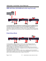
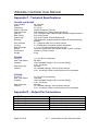
1
IS2108/4 & IS2108/8
User Manual
4 & 8 Channel LED
DMX Twinkle Controllers
© 2009
iStwinkle Controller User Manual
Contents
Section
Page
1.0 Introduction
3
2.0 Safety Instructions
3
3.0 Box Contents
3
4.0 Controls and Connections
4
5.0 Connection Options
6
6.0 Getting Started
8
7.0 Basic Operations
8
8.0 Lock
8
9.0 Main Menu
9
10.0 Effects Menu
9
11.0 Settings Menu - Mode
11
11.1 Settings Menu – DMX Address
12
11.2 Settings Menu – DMX Hold
12
11.3 Settings Menu – DMX Filter
12
11.4 Settings Menu – Display
12
12.0 Info Menu
13
Appendix A –DMX Channel Allocation
14
Appendix B – Menu Structure
15
Appendix C – Specification
16
Page 2 of 16
V1.2
©2005-2009 Innovation Solutions Limited
iStwinkle Controller User Manual
1.0 Introduction
The Innovation Solutions iStwinkle™ IS2108/4 and IS2108/8 are powerful
intelligent power supplies for the control of Innovation Solutions LED strings as
used in starcloths and scenic elements. Two models are available,
IS2108/4 – With a single output socket supporting 4 channel control
IS2108/8 – Dual output version supporting 8 channel control
The controller allows the LED's to be powered and illuminated statically or
running effects from either stand alone mode requiring no other control
equipment or from a DMX input from any DMX capable lighting control desk.
2.0 Safety Instructions
To reduce the risk of electric shock, DO NOT remove the cover!
Internal parts are not user serviceable, opening the cover will breach this
instruction and the products warranty will become null and void.
Always unplug the unit from the mains supply before moving it.
The unit must be earthed, and as such is provided with a mains cable and plug
with earth feature suitable for the country of purchase. If you have difficulty in
inserting this plug into your socket, do not try to defeat the earth mechanism,
contact an electrician for assistance.
Use the units in dry rooms only.
Use a damp cloth for cleaning the units. Do not use any cleansing agents or
solvents.
Ensure when mounting that suitable space is allowed for all ventilation holes.
When using the hanging bracket use a safety bond on the loop provided in
addition to a mounting clamp on the central hole.
3.0 Box Contents
In the box you will find the following
•
•
•
iStwinkle Controller
Mains cable
Instruction Manual
Page 3 of 16
V1.2
©2005-2009 Innovation Solutions Limited
iStwinkle Controller User Manual
4.0 Controls and Connections
The unit has to following controls and connections.
FRONT PANEL - Features
SCREEN
The 4 module, 7 segment display is used to display menu options and values. It
is also used as a status display while in use, the segments of the display that
align with the status numbers 1 to 8 shows the level of the output for each
channel.
CONTROLS
The control buttons allow navigation through the menu system and selection of
options. The controls are Enter, Down and Up. To stop accidental changes, the
menu locks automatically. To unlock the menu, press the up and down buttons
simultaneously for 2 seconds.
DMX IN
For connection to a DMX lighting control desk if not being used in stand alone
mode.
DMX OUT
For connection to other DMX controlled equipment or additional iStwinkle
controllers.
SLAVE OUT
For connection to other iStwinkle controllers when you want them to copy exactly
what the first controller in the series is doing without the need to make any
settings on them.
Page 4 of 16
V1.2
©2005-2009 Innovation Solutions Limited
iStwinkle Controller User Manual
OUTPUT
Dependent on model there are one or two output connectors labelled output 1
and output 2. Each output can control four channels of LED’s.
The outputs are wired as follows:
OUTPUT 1
1 – Channel 1
2 – Channel 2
3 – Channel 3
4 – Channel 4
5 & 6 – Common +30V
OUTPUT 2
1 – Channel 5
2 – Channel 6
3 – Channel 7
4 – Channel 8
5 & 6 – Common +30V
REAR PANEL
MAINS INPUT
Neutrik Powercon connector. A mains lead is supplied in the box to suit the
country of purchase. Input voltage is universal from 90 to 250 volts on both 50
and 60Hz for worldwide use.
FUSE
A 2 amp 20mm T2.0A Anti Surge type fuse should be used if replacement is
needed.
FANS
Fans are temperature controlled & will change speed as required, please do not
block the air flow to these or any other the other ventilation holes on the case.
Page 5 of 16
V1.2
©2005-2009 Innovation Solutions Limited
iStwinkle Controller User Manual
5.0 Connection Options
Below are examples of different control wiring scenarios. When you only have
one iStwinkle unit you can ignore the need for the connections to other units, you
can continually connect additional units in the same fashion as shown below
connecting the second unit to the third unit for each example.
TERMINATION
The end of the DMX chain needs a terminating plug, this is fitted where ever the
chain ends, so may not be connected to iStwinkle equipment when continuing the
chain onto other products but does need connecting at the end of the line.
Depending on cable lengths and equipment in the chain you may find the units
function without a terminator, but use of one is always advised. Glitches or failure
to operate from DMX are results of a terminator not being used at the end of a
DMX line.
DMX (individual control to each unit)
In this example DMX IN comes from your lighting desk and continues on to
additional units by using the DMX OUT port. On additional units you use the DMX
IN and DMX OUT ports to continue the chain, when connected like this you need
to put each controller into the relevant DMX mode you wish to use and enter the
DMX start channel for each controller. With this method as long as a different
start address for each unit is used it is possible to individually control each
iStwinkle unit.
Page 6 of 16
V1.2
©2005-2009 Innovation Solutions Limited
iStwinkle Controller User Manual
DMX with Slave (All Additional units copy first unit)
In this example DMX in comes from your lighting desk, then the additional units
are connected using the SLAVE OUT of the first controller in the chain then the
following controllers are chained using the normal DMX IN and DMX out
connections. When wired like this you only need to set the DMX address on the
first unit, all additional units will copy the first unit regardless of any settings they
have.
Stand Alone Mode
In this example no input is made to the first unit, any additional units are
connected to the SLAVE OUT socket from the first unit, additional units are
added using via the DMX IN and DMX OUT connectors.
In this example you would need to set the first unit to stand alone mode and
select the effect you wish to run, all additional units will copy the first unit without
the need to make any settings.
Alternatively if you do not wish the units to be in sequence you do not need to
connect them together you can set each of them individually to stand alone mode
and run them with just power and an output to the LED’s
Page 7 of 16
V1.2
©2005-2009 Innovation Solutions Limited
iStwinkle Controller User Manual
6.0 Getting Started
Factory Default
When the unit starts up for the first time (from factory), its default mode is for the
screen to display the status of what is happening and for it to be in Stand Alone 4
channel mode with a slow sine wave effect running.
7.0 Basic Operation
The full menu structure is show in appendix B
Following any changes in the menu settings the unit will power up in the same
mode that is was powered down from.
Start up screen
The default screen for the unit on start up and when exiting the menu structure is
the status screen, in the menu it is possible to change this default to the option of
the display going off. The Status screen shows that power is present and the
output level of the 8 outputs
(or 4 for the 4 channel version) and if a DMX or
SLAVE input signal is detected.
The Data LED status is as follows.
OFF – on input signal detected
ON – DMX input signal detected
FLASHING – Slave Input Signal detected.
8.0 Lock
A lock function is present to prevent the unit being tampered with or accidental
changes being made; on pressing any button the following is displayed.
To unlock the unit press and hold both the up and
down buttons simultaneously until the display
changes & unlocks.
Page 8 of 16
V1.2
©2005-2009 Innovation Solutions Limited
iStwinkle Controller User Manual
9.0 Main Menu
Options in the menu function are only visible relevant to the mode that you are in,
this keeps the system quick and easy to navigate.
The Main menu has the following options:
Set – Takes you to the setting menu option
Effect – Takes you to the effects options when in
Stand Alone mode, when in 8 channel mode the
options are EFF1 and EFF2 for separate effects for
the two output ports.
Info – Shows you info on the incoming DMX data,
when in DMX mode.
Done – Exits the menu system.
10.0 Effect Menu
When in stand alone mode you can enter the effects
menu to select the type of effect you wish to use
and the speed and depth of the effect to suit the
look you are after.
In four channel mode you select EFF to enter stand
alone mode, although if you have an eight output
unit and you are in 8 channel mode you select EFF1
to set effects for output 1 and EFF2 to set effects for
output 2.
Page 9 of 16
V1.2
©2005-2009 Innovation Solutions Limited
iStwinkle Controller User Manual
Once in the effects menu for the relevant mode and output you are presented
with the following options:
Effect Style EF
Here you can select the style of effect from 00 to 10.
The number after EF changes to show the effect
number.
The Effects are as follows
EF00 – OFF (Static Illumination of the cloth)
EF01 – Sine Wave Forwards
EF02 – Sine Wave Reverse
EF03 – Chase Forward
EF04 – Chase Reverse
EF05 – Inverted Chase Forwards
EF06 – Inverted Chase Backwards
EF07 – Flip Flop odd/even
EF08 – Flip Flop Inner/outer
EF09 – Bounce Chase
EF10 – All Channel Flash / Strobe
Effect Speed ES
Here you can select the speed the effect runs from
00 to 50 with 00 being static and 50 being fast, the
number displayed after ES is the speed.
Effect Level EL
Here you can select how bright the effect goes, this
is the maximum level. This can be set from 00 to 50
where 50 is full brightness.
Effect Depth Ed
Here you can select how deep (dim) a level goes
during an effect, this value is variable between 00
and 50, with 50 having the most depth and 0 being
the same as the effect level and making the effect
not visible. This is because the setting controls the
proportion of range between the Effect Level and zero.
Exiting the Effects menu
Select UP to take you back to the main menu.
Page 10 of 16
V1.2
©2005-2009 Innovation Solutions Limited
iStwinkle Controller User Manual
11.0 Settings Menu - Mode
To enter the settings menu select the SET option
from the main menu.
Mode Select
As soon as you enter the settings menu you are presented with the current mode
which will be one of the options here.
StA4 – Stand Alone 4 Channel mode
EFF option will be available in the main menu to
control the effect options; if you have an 8 output
model the second output will copy the first.
d04c – DMX 4 Channel mode
4 DMX channels are used to control outputs 1 to 4
directly proportional to the input levels for each
channel; if you have an 8 channel unit the second
output will copy the 4 channels of the first output.
d07c – DMX 7 Channel mode
7 DMX Channels are used and works exactly as in
the d04c mode except that three additional channels
allow you to control effects selection, speed and
depth. Allowing you to use the built in effects from
DMX control.
StA8 – Stand Alone 8 Channel mode
This option is for 8 channel controllers and allows
access to EFF1 and EFF2 in the main menu, giving
you the ability to select different effects for each of the
two output ports.
d08c – DMX 8 Channel Mode
This option is for 8 Channel Controllers, 8 DMX
channels are used to control outputs 1 to 8 directly
proportional to the input levels for each channel.
d14c – DMX 14 Channel Mode
This option if for 8 Channel Controllers, 14 DMX
Channels are used and works exactly like the d08c
mode except that 2 sets of three additional channels
allow you to control effects selection, speed and
depth for each of the two output ports. Allowing you
to use the built in effects from DMX control.
See appendix A for the DMX channel table for each mode.
Page 11 of 16
V1.2
©2005-2009 Innovation Solutions Limited
iStwinkle Controller User Manual
11.1 Settings Menu – DMX Address
Here the DMX start address is adjusted from 001 to
512 less the value of channels used by the current
mode selected, as setting to 510 would not allow
enough channel control before the limit of the DMX
protocol of 512 is exceeded.
The DMX address set is displayed after the letter A.
This screen is only visible when a DMX mode is selected.
11.2 Settings Menu – DMX Hold
Here you can set what happens if you loose DMX
signal to the unit. The options are:
dHon – DMX hold, unit stays in the last state if DMX
is lost
dH01 – dH60 – Adjustable from 01 to 60 when DMX is lost, the unit fades the
output to zero over the number of seconds set be this option.
11.3 Settings Menu – DMX filter
Here you can filter out issues from DMX which could
cause you to notice a flicker when dimming up and
down LED’s. As LED’s react so quickly it is possible
for you to visibly notice unsmooth fades from cheaper
lighting desks or caused by data re-sampling which
can take place in DMX combiners or other DMX distribution equipment. The
following options are available.
F AU – Auto Filter
F 00 to F250 – 0 is filtering off, other values are the time in milliseconds (ms)
over which the signal is smoothed.
11.4 Settings Menu – Display
Here you set if the display is on and showing the
status screen during operation or if it turns off so as
not to be a distraction if visible to the public.
d. on – Display On
d.off – Display Off
Exiting the Settings menu
Select UP to take you back to the main menu.
Page 12 of 16
V1.2
©2005-2009 Innovation Solutions Limited
iStwinkle Controller User Manual
12.0 Info Menu
The info menu is purely for diagnostics of an incoming DMX signal, and can be
useful information when using the filter options to sort any timing issues. The
Following information is displayed.
Number of DMX
Displays the number of DMX channels in the data
packets sent from your DMX controller. Display ends
in C for Channels.
DMX refresh frames
Displays the number of DMX packets received per
second.
Display ends in H for Hz.
DMX refresh time
Displays the time in milliseconds (ms) between each
DMX packet.
Display ends in P for period.
Example here is 22.7ms between each packet.
Page 13 of 16
V1.2
©2005-2009 Innovation Solutions Limited
iStwinkle Controller User Manual
Appendix A – DMX Channel Allocation
Channel
MODE
d04c
d07c
d08c
d14c
1
Channel 1
Channel 1
Channel 1
Channel 1
2
Channel 2
Channel 2
Channel 2
Channel 2
3
Channel 3
Channel 3
Channel 3
Channel 3
4
Channel 4
Channel 4
Channel 4
Channel 4
5
Effect Select
Channel 5
Channel 5
6
Effect Speed
Channel 6
Channel 6
7
Effect Depth
Channel 7
Channel 7
Channel 8
Channel 8
8
9
Effect Output 1 Select
10
Effect Output 1 Speed
11
Effect Output 1 Depth
12
Effect Output 2 Select
13
Effect Output 2 Speed
14
Effect Output 3 Depth
Page 14 of 16
V1.2
©2005-2009 Innovation Solutions Limited
iStwinkle Controller User Manual
Appendix B – Menu Structure
Page 15 of 16
V1.2
©2005-2009 Innovation Solutions Limited
iStwinkle Controller User Manual
Appendix C - Technical Specifications
IS2108/4 and IS2108/8
Input Voltage
Power
Frequency
Mains Connector
Input protection
DMX IN
DMX THRU
SLAVE OUT
Dimming
User Interface
Cooling
DMX Channels
Effects
Dimensions
Weight
95 -250 VAC
180 watts
47 / 63 Hz
Neutrik Powercon (Type A)
Rear Panel Fuse. T2amp 20mm Anti Surge
5 pin XLR Male Opto-isolated DMX input with surge protection
5 pin XLR Female
5 pin XLR Female, Ground Referenced
High Resolution smooth filtered Innovation Solutions dimming
protocol.
4 x 7 Segment LED and 3 control buttons.
2 x Temperature Controlled variable speed fans
4, 7, 8 or 14 Channel Dependant on mode
10 built in effects each with variable depth / speed / Intensity.
234mm x 175mm x 60mm
2.2kg
IS2108/4
OUTPUT
Max Total Output
Capacity
Max Output per
channel.
1 x 6 pin XLR (4 Channels)
96 watts
128 x Standard Strings, 512 Low power strings
or 8 x 1w Strings
24 watts
32 x Standard Strings, 128 Low power strings
or 2 x 1w Strings. Ensure total maximum is not exceeded.
IS2108/8
OUTPUT
Max Total Output
Capacity
Max Output per
channel.
2 x 6 pin XLR (8 Channels)
120 watts
160 x Standard Strings, 640 Low power strings
or 8 x 1w Strings
24 watts
32 x Standard Strings, 128 Low power strings
or 2 x 1w Strings. Ensure total maximum is not exceeded.
Appendix D – Output Pin Connections
OUTPUT 1
1 – Channel 1
2 – Channel 2
3 – Channel 3
4 – Channel 4
5 & 6 –Common +30v
Page 16 of 16
OUTPUT 2
1 – Channel 5
2 – Channel 6
3 – Channel 7
4 – Channel 8
5 & 6 –Common +30v
V1.2
©2005-2009 Innovation Solutions Limited