1
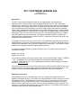
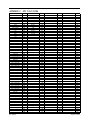
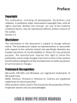
SUGGESTED SURROUND SOUND SPEAKER PLACEMENT
FRONT-CENTRE
FRONT-LEFT
FRONT-RIGHT
A sub-woofer is often
located out of the way
due to its inherent lack of
directionality
30 0
Centre line
11
0
00
11
0
300
The LEFT SURROUND and RIGHT SURROUND
speakers should be positioned the at -110 degrees
and +110 degrees from centre respectively.
LEFT-SURROUND
Single Back Surround speaker,
if used, should be located on the
centre line behind the listener.
RIGHT-SURROUND
If two Back Surround speakers are used, in a “7.1”
system, they should be placed equidistant from the
centre line and behind the listeners such that they do not
point directly at the listeners.
VERTICAL PLACEMENT OF SPEAKERS
The front speakers are normally placed at ear level, but
where the front-centre speaker is placed on top of the
television or video monitor the front-left and front-right
speakers should be elevated to be in-line with the
centre speaker
Surr-snd-spkr-placement-1.cdr
SP1.7 SOFTWARE VERSION 44A
2003 NOV 20
Author: Shane Parfitt
Digital Force
The SP1.7 has always automatically locked-on to the digital signal, and automatically
implemented the correct decoding. When the digital bitstream is lost, the SP1.7 has always
defaulted to the analog input. This is useful for source material that can have a mix of digital and
analog outputs, such as digital cable boxes. We have discovered that there exists a few digital
source components that will temporarily turn off their digital outputs under switching conditions.
This is mainly a problem with certain satellite receivers while changing channels. This temporary
break in the digital bitstream causes the SP1.7 to lose lock on the digital signal and default to the
analog input. When the new channel kicks in the SP1.7 will automatically go back to the digital
input and implement the correct decoding. The problem is that this operation of switching to
analog and back to digital takes some time in the SP1.7 causing an interruption in the audio, and
sometimes some transient noises.
The Digital Force feature is a way to stop the SP1.7 from defaulting to the analog input when the
digital bitstream is interrupted. When the digital force feature is on, the SP1.7 will simply mute it’s
output when the bitstream is lost, and it will not default to the analog input. This results in a better
response when changing channels on digital satellite receivers.
To enable or disable this feature, a ‘hidden’ IR code is used. The codes to turn this feature on
and off are as follows:
Digital Force On: 061
Digital Force Off: 062
So, to enable this feature from the IR remote control, you would press CODE – MUTE – STEREO
- THX. A message on the LCD display will appear to verify that the operation has been
completed. Please see the SP1.7 user manual and our website for more information on hidden
IR codes. www.bryston.ca
This feature is also ‘Saved per Input’ which means that you have to press the SAVE button on the
IR remote control if you want this feature to be associated with the currently selected input. This
operation must be repeated for each input that you want the feature to be enabled for.
Xtra Bass Level Control
The Xtra Bass mode can be activated when there is a 2-channel input signal and the Front
Speakers are defined as Large. This causes a Low-Pass-Filtered, summed L+R signal to be sent
the subwoofer output. The Xtra Bass Level control allows you to control the level of this signal,
independently from the Subwoofer level control. This means that the Xtra Bass Level control
takes over as the Subwoofer Level control, but only when the Xtra Bass mode is activated. This
allows for much smoother Bass blending with full range speakers. The Xtra Bass Level Control is
found as the ‘XB’ item in the ‘Other Settings’ Menu.
Dolby Digital EX
With previous versions of the SP1.7 software, the only way to get 6.1 or 7.1 operation with a
Dolby Digital signal was to engage THX Surround EX. We have extended our license with Dolby
to allow Dolby Digital EX, in the absence of any THX post processing. To engage this mode of
operation, four conditions must be satisfied.
1.
2.
3.
4.
The Back Speakers must be enabled in the ‘Speaker Config’ Menu as ‘ONE’ or ‘TWO’
The EX Control variable in the ‘Other Settings’ Menu must be set to ‘AUTO’ or ‘ON’
The Surround listening mode must be engaged from the front panel or IR remote control.
A 5.1 channel Dolby Digital signal must be present at the input. If EX_Control=AUTO, the
bitstream must contain the EX flag for Dolby Digital EX decoding to engage. If
EX_Control=ON, the Dolby Digital EX decoding will be forced on for all 5.1 channel Dolby
Digital signals.
DTS-ES operation is unaffected by these changes, and functions as before on DTS signals
governed by the ES_Control variable in the ‘Other Settings’ Menu.
More ‘Saved per Input’ Variables
The following are settings that are stored “WITH EACH INPUT” when the SAVE button is
pressed on the IR remote control instead of the current “GLOBAL” save.
New Saved Settings:
•
•
•
•
•
•
Center Channel Level
Back Channel Levels
Crossover Frequency
Bass Peak Level Manger (BPLM)
Digital Force
Xtra Bass Level
Current Saved Settings are Retained:
•
•
•
•
•
•
•
•
•
•
•
•
•
•
•
•
Rear Channel Levels
Subwoofer Level
OSD Assignment (for SPV-1)
OSD Enable (for SPV-1)
Digital
Listening Mode
Surround Mode for THX listening mode
Surround Mode for Surround listening mode
EX Control
ES Control
PLII Panorama
PLII Center Width
PLII Dimension
Bypass Mode
Speaker Configuration
Xtra Bass Enable
BRYSTON SP1.7 RS-232 PROTOCOL
(REV 5 – MARCH 2003)
For Version 43C Firmware and later.
Source Switching
Autofeedback Returns
SAT↵
DVD↵
CD↵
AUX↵
VCR↵
TP↵
switch
switch
switch
switch
switch
switch
to
to
to
to
to
to
SAT input
DVD input
CD input
AUX input
VCR input
TAPE input
DI↵
DIN↵
DIF↵
toggle DIGITAL on/off
force DIGITAL on
force DIGITAL off
“SAT”
“DVD”
“CD”
“AUX”
“VCR”
“TP”
“ON” or “OFF”
“ON”
“OFF”
Listening Modes
THX↵
SUR↵
ST↵
MN↵
SV↵
THX Surround listening mode
Surround listening mode
Stereo listening mode
Mono listening mode
Save mode settings for current input
“THX”
“SUR”
“ST”
“MN”
Bypass Modes
BP↵
BP2↵
BP6↵
BPF↵
cycle
force
force
force
Bypass
Bypass
Bypass
Bypass
Modes 2ch/5.1ch/off
Mode Stereo
Mode 5.1 channel
Mode off
“BP2”,“BP6” or Listening Mode
“BP2”
“BP6”
Listening Mode
Surround Modes (submodes of THX and Surround listening modes for 2ch input)
SM↵
EF00↵
EF01↵
EF02↵
EF03↵
EF04↵
EF05↵
EF06↵
EF07↵
EF08↵
EF09↵
EF10↵
EF11↵
EF12↵
EF13↵
cycle through Surround Modes
No Effect
Pro Logic
PLII Music
PLII Movie
Neo:6 Music
Neo:6 Movie
Stereo5
Party
Hall
Church
Stadium
Club
Theatre
Natural
“EF00” to “EF13”
“EF00”
“EF01”
“EF02”
“EF03”
“EF04”
“EF05”
“EF06”
“EF07”
“EF08”
“EF09”
“EF10”
“EF11”
“EF12”
“EF13”
Extended Surround Options
EXN↵
EXF↵
EXA↵
ESN↵
ESF↵
ESA↵
THX Surround EX ‘On’
THX Surround EX ‘Off’
THX Surround EX ‘Auto’
DTS-ES ‘On’
DTS-ES ‘Off’
DTS-ES ‘Auto’
Volume Commands
GVxx↵ where xx is –(desired_volume)+12
VU↵
VD↵
MT↵
MTN↵
MTF↵
volume up
volume down
mute Toggle
mute ON
mute OFF
range: 0 (highest) to
Note: accurate within
“XXX.X” from –80.0 to
“XXX.X” from –80.0 to
“MUTE” or “UNMUTE”
“MUTE”
“UNMUTE”
80 (mute)
3dB
11.5
11.5
Preset Speaker Configurations
SC1↵
SC2↵
SC3↵
SC4↵
S/S/S/Y
L/S/S/N
L/L/L/N
L/N/N/N
Status Query
SS1↵
SS2↵
SS3↵
SS4↵
SS5↵
SS6↵
SS7↵
QSN↵
returns
returns
returns
returns
returns
returns
returns
returns
listening mode
input signal type
source
Digital
Effect/Surround mode
LCD decoding mode strings
Master Volume
serial number
“THX”,”SUR”,”ST”,“MN”,”BP2”,”BP6”
see below
“SAT”,”DVD”,“CD”,”AUX”,”VCR”,”TP”
“ON” or “OFF”
“EF00” to “EF12”
see SP1.7 Manual Appendix A
“-35.5”
Power
PU↵
PD↵
Power Up
Power Down
“SP1 OS v43C” and initial volume
Automatic Feedback
AFY↵
AFN↵
enables automatic feedback
disables automatic feedback
Whenever any change is made from the Front Panel, IR, or RS232, the change
will be reported through the RS232 port if the Automatic Feedback mode is
engaged.
Communication
For SP1.7 with S/N lower than 000398
Pin 2 Receive Data (Rx)
Pin 3 Transmit Data (Tx)
Pin 5 Ground
*requires a NULL MODEM DB9 Cable for most applications
For SP1.7
Pin
Pin
Pin
with S/N greater than (or equal) to 000398
2 Transmit Data (Tx)
3 Receive Data (Rx)
5 Ground
Communication: 9600, 8, N, 1
Software Flow Control:
After the SP1.7 receives a command, interrupts must be disabled while
the main microcontroller communicates with the DSP module. In this
state, the SP1.7 is not ready to receive the next command. When the
current command is completed, the SP1.7 will return a ‘>’ character
feedback. This indicates that the SP1.7 is ready to receive the next
command. The host system should wait for this character before sending
the next command. Also, when an illegal/unknown command is received at
the RS232 port, the SP1.7 will return a ‘!’ character.
Input Signal Strings
“UNKNOWN”
“PCM”
“Analog”
“DL D x/x.x”
“DTS x/x.x”
eg.
“DL D 3/2.1”
(front/rear/sub)
APPENDIX C - SP1.7 IR-CODES
Function
Code
Function
Code
Power Off
TV/SAT
DVD
CD
AUX
VCR
TAPE
Volume Up
Volume Down
Mute
Test
Digital
Dolby
Stereo
THX
Power On/Off
DTS
Surround
Mode
Menu Up
Menu Down
Select
Centre
Rear
Back
Subwoofer
Save
2-Ch Bypass On/Off
6-Ch Bypass On/Off
Power On
SPV-1 Reserved
SPV-1 Reserved
SPV-1 Reserved
SPV-1 Reserved
SPV-1 Reserved
SPV-1 Reserved
SPV-1 Reserved
SPV-1 Reserved
SPV-1 Reserved
SPV-1 Reserved
SPV-1 Reserved
SPV-1 Reserved
SPV-1 Reserved
SPV-1 Reserved
SPV-1 Reserved
SPV-1 Reserved
SPV-1 Reserved
SPV-1 Reserved
SPV-1 Reserved
OSD On/Off
OSD Off
OSD On
Mono
2-Ch Bypass On
6-Ch Bypass On
Bypass Off
Digital On
Digital Off
Mute On
Mute Off
Bypass Sub On/Off
000
001
002
003
004
005
006
007
008
009
010
011
012
013
014
015
016
017
018
019
020
021
022
023
024
025
026
027
028
029
030
031
032
033
034
035
036
037
038
039
040
041
042
043
044
045
046
047
048
049
050
051
052
053
054
055
056
057
058
059
060
061
062
063
Mode None
Pro-Logic
PLII Music
PLII Movie
Neo-6 Music
Neo-6 Movie
Stereo 5
Party
Hall
Church
Stadium
Club
Theatre
Natural
064
065
066
067
068
069
070
071
072
073
074
075
076
077
078
079
080
081
082
083
084
085
086
087
088
089
090
091
092
093
094
095
096
097
098
099
100
101
102
103
104
105
106
107
108
109
110
111
112
113
114
115
116
117
118
119
120
121
122
123
124
125
126
127
Rev. 600-39
Function
Code
128
129
130
131
132
133
134
135
136
137
138
139
140
141
142
143
144
145
146
147
148
149
150
151
152
153
154
155
156
157
158
159
160
161
162
163
164
165
166
167
168
169
170
171
172
173
174
175
176
177
178
179
180
181
182
183
184
185
186
187
188
189
190
191
Function
Auto Save On/Off
X-Over On/Off
Code
192
193
194
195
196
197
198
199
200
201
202
203
204
205
206
207
208
209
210
211
212
213
214
215
216
217
218
219
220
221
222
223
224
225
226
227
228
229
230
231
232
233
234
235
236
237
238
239
240
241
242
243
244
245
246
247
248
249
250
251
252
253
254
255
August 12, 2002