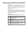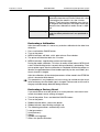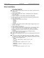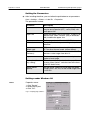
1
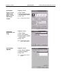
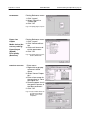
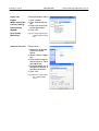
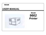
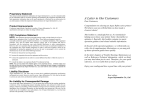
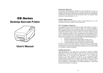
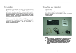
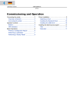
07/02 Rev. 2.16-00
USER MANUAL
Seite / Page 1
AP 3.4
Commissioning and Operation
Connecting the printer ................................... 2
Printer connectors ..................................... 2
Connecting the printer ............................... 2
Operator Controls ......................................... 3
Buttons ...................................................... 3
LED indicators ........................................... 4
Basic Operations ........................................... 5
Printing a Configuration Report ................. 5
Performing a Calibration ........................... 6
Performing a Factory Reset ...................... 6
Driver Installation ........................................... 8
Installing „Label Dr.“ ................................... 8
Setting the Parameters .............................. 9
Settings under Windows 98 ....................... 9
Settings under Windows 2000 ................. 11
Settings under Windows NT 4.0 .............. 13
Settings under Windows XP .................... 14
Index ............................................................ 16
07/02 Rev. 2.16-00
USER MANUAL
Commissioning and Operation, page 2
AP 3.4
Connecting the printer
à
Never operate the printer in an area where it can get wet!
Printer connectors
Ä
Â
Ã
À
Á
Fig. 1: Printer connectors (rear side of the device).
• Centronics connector (parallel port) (1)
For parallel port connection. Mostly it is connected to the printer port of a PC.
• RS232 connector (serial port) (2)
For serial port connection. Mostly it is connected to the COM. port of a PC.
• AC power socket (3)
For AC power connection.
Connecting the printer
1. Leave the power switch (4) at the “O” Position.
2. Connect the power supply plug to the power jack (3) and the other end of
the cord to your AC outlet (5) (see Fig. 1).
3. Connect the printer with any standard Centronics cable to the parallel port of
the host computer and to the Centronics connector (1) of the printer.
Alternatively, you can connect the printer with a serial cable to the RS232C
port of your computer or terminal. To do so, plug the end of the cord which
carries the male plug to the RS232 connector (2) of the printer!
à
à
Using Centronics allows for a much higher communication speed than the
use of a serial!
07/02 Rev. 2.16-00
USER MANUAL
Commissioning and Operation, page 3
AP 3.4
Operator Controls
Power switch
Fig. 2: Operator controls of the printer.
Buttons
There are three buttons (see Fig. 2), each having two basic functions.
BUTTON Pressed at normal status
Pressed during power-on
FEED
Feed a label.
Perform a self test for configuration report.
PAUSE
Stop the printing process
Resume the printing job after
press it again.
Perform the media calibration.
CANCEL
Interrupt and delete the printing Reset the settings at E2PROM.
job.
Force the printer to continue
working after an error had been
solved.
Tab. 1: Overview buttons.
• FEED Button
The FEED button forces the printer to feed one label when printer is idle (not
printing) or if in PAUSE state.
Holding down the FEED Button then turning on the power switch, the printer
will perform a self test and a configuration report will be printed.
07/02 Rev. 2.16-00
USER MANUAL
Commissioning and Operation, page 4
AP 3.4
• PAUSE Button
The PAUSE Button stops and restarts the printing process in normal operation. If the PAUSE button is pressed while printing is in progress, the printing
stops once current label is completed. Press this button again to restart the
printing.
Holding down the PAUSE Button then turning on the power switch, the printer
will perform the media sensor calibration.
• CANCEL Button
The CANCEL Button interrupts and deletes the current printing job. If there is
an error indication occurs, pressing this button to cancel the error indication.
Holding down the CANCEL Button then turning on the power switch , the printer will perform a system reset , all the parameters which are stored in EEPROM will be rest to default value.
LED indicators
There are three LED indicators on the front panel, ”READY”, ”MEDIA” and
”RIBBON”. These indicators display the operation status of the printer.
LED
Meaning
READY
The READY indicator will remain lighted except if any of the following conditions prevail.
- Receiving data from host
- A fault condition
MEDIA
The MEDIA indicator will remain on for the normal operation of
the printer.
- The printer is at PAUSE state
- Blinking – Media run out (READY will be also blinking)
RIBBON
ON - under thermal transfer mode with ribbon installed.
OFF - under direct thermal mode. (No ribbon installed)
Set by Windows driver or command.
- Blinking - Ribbon run out (READY will be also blinking)
Tab. 2: Overview LED indicators.
07/02 Rev. 2.16-00
USER MANUAL
Commissioning and Operation, page 5
AP 3.4
Basic Operations
Printing a Configuration Report
1.
2.
3.
4.
Turn off the printer. Press and hold the FEED button.
Turn on the power.
READY indicator blinks, release FEED button.
The printer will perform a self test and print out a configuration report
(see Fig. 3).
5. READY indicator stops blinking and lights up.
6. The following information will be printed on this report.
After self test the printer will enter character dump mode. For normal operation press the CANCEL button to stop dump mode.
à
Fig. 3: Configuration report.
Some information in the configuration report are important, please check
them after the self test:
Item
Meaning
Printer programming
language
The printer programming language is listed on the
first line of the report . There are two different languages (PPLA and PPLB), Please check for correct version.
CHECKSUM
The CHECKSUN of the FLASH ROM is listed on
the eighth line, It should be 0000.
Tab. 3: Items on the Configuration Report.
07/02 Rev. 2.16-00
USER MANUAL
Commissioning and Operation, page 6
AP 3.4
Media height:
The height of the media (label paper) is list on the
second line from the end. Please check this value
if the height of the media is less the 2 inches
(50 mm). The listed value should be very close to
the height of the media plus the height of one gap,
otherwise the calibration of media sensor is required.
Label count and length This message shows the number of labels and
length has been printed since it was produced at
factory.
Tab. 3: Items on the Configuration Report.
Performing a Calibration
After the media loaded, it is necessary to do the calibration for the label size
detection.
1.
2.
3.
4.
5.
Press and hold the PAUSE button.
Turn on the power.
MEDIA indicators will blink, at this point release Pause button.
The printer will feed the labels for 12 inches.
MEDIA indicators stop blinking and remain illuminated.
During the media calibration, 12 inches of media will be fed out. MEDIA indicators will be blinking for few seconds during calibration is proceeding. Then
turn on printer again after the calibration is completed. Without the proper calibration, the gap detection will not stable especially for the small labels (less
than 2.0 inches in height).
à
After the calibration, all the related parameters will be stored in the EEPROM
which is located on Main board.
This procedure is very important and must always be carried out after installation and every time the media type is changed. Failure to do so will result in
the gap and label-empty detection being incorrect.
Performing a Factory Reset
If you would like to reset the printer to its factory defaults after certain commands have been sent or settings changed:
1.
2.
3.
4.
5.
Turn off the printer. Press and hold the CANCEL button.
Turn on the power.
Ribbon indicator blinks, release the button.
Ribbon indicator stops blinking and lights up.
The following parameters automatically reset.
• Label parameters
• Heat(Darkness)
• Speed
• Symbol set (language)
• Others for specific emulation
07/02 Rev. 2.16-00
USER MANUAL
Commissioning and Operation, page 7
AP 3.4
à
à
à
All settings stored in non-volatile E 2PROM cannot be destroyed even by
turning the printer off.
It is necessary to perform label sensitivity calibration after resetting.
The printed label count can not be reset.
07/02 Rev. 2.16-00
USER MANUAL
Commissioning and Operation, page 8
AP 3.4
Driver Installation
à
Installing „Label Dr.“
Before installation, please make sure your ”user’s right” is up to the level of
‘Administrator'.
1. Click the ”Start” button.
2. Select ”Setting”, then select ”Printers” and double click the ”Add Printer”
icon. Click ”Next”.
3. Click the ”Network” or ”Local” button and click the ”Next” button.
4. Click ”Have Disk”, click the pull-down menu to select CD ROM driver path.
5. Click ”Browse” button.
6. Select the proper directory for installation:
– WIN98
– WIN2000
– NT4.0
– WIN XP
7. The driver name ”Label Dr. 200” (or Label Dr.300) will appear in the ”List of
Printers”, click ”Next”.
8. Select ”Replace Existing Driver”.
9. Select the communication port for the label printer. For parallel port, select
”LPT1:”, ”LPT2:” or ”LPT3:”, for serial port select ”COM1:” or ”COM2:”.
10. After the related files have been copied to your system, the installation is
complete.
11. If you need to print from the label printer, set ”Label Dr. 200” (or
Label Dr. 300) as the Default Printer.
If you are just updating your driver, make sure to delete the previous version
first!
à
à
If you install a new bar code application software like ArgoBar, LabelLView
or CodeSoft, the Label Dr. 200 (or Label Dr. 300) driver should be activated
and set as the current printer driver:
– ArgoBar
File >New > Select Printer > Label Dr. on LPT1 > OK
– LabelView
File >Select Printer > Label Dr. on LPT1: > OK
– CodeSoft
File >Printer > W indows > Label Dr. on LPT1: > OK
– LabelMatrix
File >Printer Setup > Label Dr. on LPT1: > OK
07/02 Rev. 2.16-00
USER MANUAL
Commissioning and Operation, page 9
AP 3.4
Setting the Parameters
Ô After installing the driver, you can follow the path below to set parameters:
Start > Settings > Printers > Label Dr. > Properties
The parameters include:
Parameter
Description
Ports
Select the IO port to link with the printer. The port
may be one of parallel (LPT), serial (COM), net
work port or file.
Paper size
Select the proper size on the menu. If there is no
desired size, select ”Custom” (only in Win98/95/
Me) to define the paper size.
Create a new size
Define paper size in Win 2000/XP/NT4.0.
Orientation
Set portrait or landscape according to the print
direction.
Paper source
(Media type)
T/T stands for thermal transfer (ribbon) mode and
D/T for direct thermal mode (without ribbon).
Media choice
(Darkness)
Set the heat value or darkness from this field. The
darkness value ranges from 0 to 15.
Copies
This function designates the number of printed
copies of each page.
More option (Accessory setting)
To use the cutter and peeler function you still need
to enter „More Options“ and select one of the items.
(Set DIP Switch also).
Device options
(Speed)
Set the printer speed. For the R-400, the speed
ranges from 1 to 6 IPS, for the R-600 ranges from
1 to 4 IPS.
Tab. 1: Parameters included in the „Label Dr.“ driver.
Settings under Windows 98
Ports
Properties menu:
1. Click ”Details”.
2. Select the IO port.
3. Click ”OK”.
Fig. 4: Property page „Details“.
07/02 Rev. 2.16-00
USER MANUAL
AP 3.4
Orientation
Properties menu:
Paper source
(Media type)
1. Click "Paper".
2. Click each item to select desired parameter.
3. Click "OK".
Media choice
(Darkness)
Copies
Fig. 5: Property page „Paper“.
Output bin
(Accessory setting)
Properties menu:
1. Click "Paper"
2. Click "more option"
3. Select Enable / without
cutter, peeler
4. Click "OK"
Fig. 6: Property page „Paper“,
button „More Options“.
Print quality
(Speed)
Properties menu:
1. Click" Device Options"
2. Select parameters
3. Click "OK"
Fig. 7: Property page „Device
Options“.
Commissioning and Operation, page 10
07/02 Rev. 2.16-00
USER MANUAL
AP 3.4
Create User Defined Paper
Properties menu:
1. Click "Paper"
2. Select "Custom"
3. User-Define size
4. Set up a new size
5. Click "OK"
Fig. 8: Property page „Paper“,
„User Defined Size“.
Settings under Windows 2000
Ports
Properties menu:
1. Click "Ports"
2. Select the IO port
3. Click "OK"
Fig. 9: Property page „Ports“.
Paper source
(Media type)
Back to Printers menu:
1. Label Dr.
2. Right click to get popup menu
3. Select "Printing Reference"
4. Click "Paper Quality"
5. Select media type
6. Click "OK"
Fig. 10:Property page „Paper
Quality“.
Commissioning and Operation, page 11
07/02 Rev. 2.16-00
USER MANUAL
AP 3.4
Orientation
Printing Reference menu:
1. Click "Layout"
2. Select "Portrait" or
"Landscape"
3. Click "OK"
Fig. 11:Property page „Layout“.
Paper size
Printing Reference menu:
Copies
Paper/Output
(Speed)
1. Click "Layout"
2. Click "Advanced" button
3. Click each item to select the parameters
4. Click "OK"
Print quality
(Darkness)
Fig. 12:Property page „Layout“,
button „Advanced“.
Media choice (Accessory setting)
Create a new size
Printer menu:
1. Right click to get popup menu in blank
space.
2. Select "Server Properties".
3. Enter a form name for
the new form in "Form
description for".
4. Reset the paper size in
the specific squares of
the "Measurements".
5. Click "OK"
Fig. 13:Top: Context menue after right click. Below:
Menue „Print Server
Properties“.
Commissioning and Operation, page 12
07/02 Rev. 2.16-00
USER MANUAL
Commissioning and Operation, page 13
AP 3.4
Settings under Windows NT 4.0
Ports
Properties menu:
1. Click "Ports".
2. Select the IO port.
3. Click "OK".
Fig. 14:Property page „Ports“.
Paper size
Printers menu:
Orientation
1. Label Dr.
2. Right click to get popup menu
3. Select "Document Defaults"
4. Click "Advanced" button
5. Click each item to select desired parameter
Paper source
(Media type)
Copies
Media choice(Accessory setting)
Fig. 15:Menue „Document Defaults“, property page
„Advanced“.
Paper/Output
(Speed)
Print quality
(Darkness)
Default Document menu:
1. Click "Advanced"
2. Click each item to select desired parameter
3. Click "OK"
Fig. 16:Menu „Default Document“, property page
„Advanced“.
Create a new size m Refer to paragraph Create a new size on page 12
07/02 Rev. 2.16-00
USER MANUAL
AP 3.4
Settings under Windows XP
Ports
Properties menu:
1. Click "Ports"
2. Select the IO port
3. Click "OK"
Fig. 17:Property page „Ports“.
Paper source
(Media type)
Back to Printers menu:
1. Label Dr.
2. Right click to get popup menu
3. Select "Printing Reference"
4. Click "Paper Quality"
5. Select media type
6. Click "OK"
Fig. 18:Menue „Printing Reference“, property page
„Paper Quality“.
Orientation
Printing Reference menu:
1. Click "Layout"
2. Select "Portrait" or
"Landscape"
3. Click "OK"
Fig. 19:Menue „Printing Reference“, property page
„Layout“.
Commissioning and Operation, page 14
07/02 Rev. 2.16-00
USER MANUAL
AP 3.4
Paper size
Printing Reference menu:
Copies
1. Click "Layout".
2. Click "Advanced" button.
3. Click each item to select the parameters.
4. Click "OK".
Media choice (Accessory setting)
Paper/Output
(Speed)
Print quality
(Darkness)
Create a new size
Fig. 20:Property page „Layout“,
„Advanced“ button pressed.
Printer menu:
1. Right click to get popup menu in blank
space.
2. Select "Server Properties".
3. Enter a form name for
the new form in "Form
description for".
4. Reset the paper size in
the specific squares of
the "Measurements".
5. Click "OK".
Fig. 21:Menue „Server Properties“, property page
„Form“.
Commissioning and Operation, page 15
07/02 Rev. 2.16-00
USER MANUAL
Commissioning and Operation, page 16
AP 3.4
Index
B
D
Buttons 3
C
Driver installation 8
F
Calibration 6
Centronics 2
Configuration report 5
Connector 2
Factory defaults 6
L
LED indicators 4
R
RS232 2