1
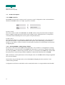
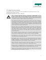
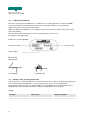
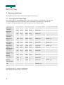
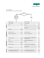
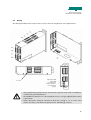
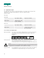
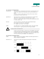
OPERATING INSTRUCTIONS
EC MOTOR CONTROLLER (ECMR)
Electrical and Software Documentation
BA-100078
Starting from serial number 429991
English edition 02/2008
Operating Instructions
EC Motor Controller (ECMR)
Contents
1
1.1
Important information __________________________________________________________ 3
Introduction____________________________________________________________________ 3
1.2
EU declaration of conformity (pursuant to MRL Appendix II A) _______________________ 3
1.3
Product description _____________________________________________________________ 4
1.3.1
ECMR controller ________________________________________________________________ 4
1.3.2
“Start-up ECMR” commissioning software _________________________________________ 4
1.4
Proper use _____________________________________________________________________ 5
1.4.1
ECMR controller ________________________________________________________________ 5
1.4.2
“Start-up ECMR” commissioning software _________________________________________ 6
1.5
Dangers and safety information __________________________________________________ 7
1.6
Additional information __________________________________________________________ 8
1.7
Validity of the operating instructions ______________________________________________ 8
2
Dimensional drawing ___________________________________________________________ 9
3
3.1
Overview (quick start) _________________________________________________________ 10
Select appropriate voltage supply _______________________________________________ 10
3.2
Procedure ____________________________________________________________________ 11
4
4.1
Installation ___________________________________________________________________ 12
Mounting _____________________________________________________________________ 12
5
5.1
Position control _______________________________________________________________ 13
Overview _____________________________________________________________________ 13
5.2
Technical data _________________________________________________________________ 14
5.3
On and Off switching behavior __________________________________________________ 15
5.4
Emergency-off function_________________________________________________________ 16
5.5
Reference run sequence ________________________________________________________ 17
5.6
Motion task sequence __________________________________________________________ 18
5.7
Wiring ________________________________________________________________________ 19
5.7.1
Voltage supply ________________________________________________________________ 20
5.7.2
Components (DAE, KUSE) ______________________________________________________ 21
5.7.3
Digital inputs__________________________________________________________________ 22
5.7.4
Digital outputs ________________________________________________________________ 23
5.7.5
Communication________________________________________________________________ 23
5.7.6
Conductor cross section ________________________________________________________ 23
5.8
Digital inputs/outputs __________________________________________________________ 24
5.8.1
Functions of the digital inputs ____________________________________________________ 24
5.8.2
Functions of the digital outputs _________________________________________________ 26
5.9
Status display _________________________________________________________________ 26
5.10
ECMR commissioning software __________________________________________________ 27
5.10.1
Communication________________________________________________________________ 28
5.10.2
Configuration _________________________________________________________________ 28
1
Operating Instructions
EC Motor Controller (ECMR)
5.10.2.1 Motion tasks__________________________________________________________________ 30
5.10.2.2 I/O configuration ______________________________________________________________ 37
5.10.2.3 Errors ________________________________________________________________________ 41
5.10.3
Parameters ___________________________________________________________________ 44
5.10.4
Status line ____________________________________________________________________ 46
5.11
Teach-In______________________________________________________________________ 47
5.12
Threshold values ______________________________________________________________ 48
6
6.1
Torque control _______________________________________________________________ 50
Overview_____________________________________________________________________ 50
6.2
Technical data ________________________________________________________________ 51
6.3
On and Off switching behavior__________________________________________________ 52
6.4
Emergency-off function ________________________________________________________ 52
6.5
Wiring _______________________________________________________________________ 53
6.5.1
Voltage supply ________________________________________________________________ 54
6.5.2
Components__________________________________________________________________ 54
6.5.3
Digital inputs _________________________________________________________________ 55
6.5.4
Digital outputs ________________________________________________________________ 55
6.5.5
Communication _______________________________________________________________ 56
6.5.6
Conductor cross section _______________________________________________________ 56
6.6
Digital inputs/outputs__________________________________________________________ 56
6.6.1
Functions of the digital inputs __________________________________________________ 57
6.6.2
Functions of the digital outputs _________________________________________________ 57
6.7
Status display _________________________________________________________________ 58
6.8
Potentiometers _______________________________________________________________ 58
6.9
ECMR commissioning software _________________________________________________ 59
6.9.1
Communication _______________________________________________________________ 60
6.9.2
Configuration _________________________________________________________________ 60
6.9.2.1
I/O configuration ______________________________________________________________ 62
6.9.3
Parameters ___________________________________________________________________ 62
6.10
Status line ____________________________________________________________________ 63
6.11
Threshold values ______________________________________________________________ 63
7
Accessories __________________________________________________________________ 64
8
Parts lists for ECMR __________________________________________________________ 65
9
9.1
General information __________________________________________________________ 67
Environmental compatibility and disposal ________________________________________ 67
2
Operating Instructions
EC Motor Controller (ECMR)
1
1.1
Important information
Introduction
These Operating Instructions cover among other things the functional scope, technical data, load
limits, installation and spare parts of the EC Motor Controller.
These Operating Instructions are part of the overall documentation of the electrical components.
The overall documentation consists of the following documents:
Operating Instructions
Device
BA-100078
ECMR
BA-100058
KUSE
BA-100074
DAE
BA-100069
GPE
BA-100070
GWE
– This document must be read before commissioning. Incorrect handling of the
EC Motor Controller (ECMR) may lead to injury to persons, material damage and
loss of the right to warranty claims. All technical data and specifications concerning
connection conditions must be strictly observed.
– Basic knowledge of the Windows operating system and operation of a personal
computer are required. Information about safety, installation and commissioning
must be strictly observed.
1.2
EU declaration of conformity (pursuant to MRL Appendix II A)
Directives and standards taken into account:
Machinery Directives 89/392/EEC, 91/368/EEC
Manufacturer:
Montech AG, Gewerbestrasse 12 CH-4552 Derendingen, Switzerland
Tel. +41 32 681 55 00, Fax +41 32 682 19 77
3
Operating Instructions
EC Motor Controller (ECMR)
1.3
Product description
1.3.1 ECMR controller
The ECMR can be used for torque control or position control. It depends on the connected device
whether the ECMR works as a torque or position controller:
KUSE
DAE
!
Position control
GPE
GWE
!
Torque control
Position control
The motion tasks stored in the EEPROM of the ECMR can be selected and started via the digital
inputs. A digital output reports the arrival at the target position. All key functions of the position
controller can be initiated by the control system of any manufacturer.
Torque control
The movement direction is selected via a digital input. The device then travels to the end position.
The desired “Current” torque and maximum travel “Speed” can be defined by potentiometers.
Further, it is possible to select from three stored torques and three stored maximum travel speeds
via digital inputs.
1.3.2 “Start-up ECMR” commissioning software
The device connected to the ECMR must be adjusted to the conditions of the application. Setting
the parameters is not performed on the ECMR itself, but rather on a personal computer (PC) using
the “Start-up ECMR” commissioning software. The PC is connected to the ECMR with a null modem
line (serial). The commissioning software establishes communication between PC and ECMR.
With a minimum of effort parameters can be changed, sent to the ECMR and the changes applied in
the connected device.
Actual values are periodically read out from the ECMR and displayed in the status line of the
commissioning software.
Configurations and motion task tables can be saved (archived) to a storage medium and reloaded.
4
Operating Instructions
EC Motor Controller (ECMR)
The following minimum requirements must be met in order to commission the ECMR using the
“Start-up ECMR” software:
Processor:
Operating system:
Graphics card:
Resolution:
Drives:
Memory:
Interface:
Intel Pentium or higher
WINDOWS Vista, XP, 2000, NT, ME, 98, 95
Windows compatible, color
At least 800 x 600 pixels
CD drive
Hard disk (5 MB available) (software can be run from the CD)
At least 8 MB
Serial port RS232 (COM port)
The interface cannot be used by other software (e.g. drivers).
1.4
Proper use
1.4.1 ECMR controller
The ECMR controller is used for operating electrical automation components and belongs to the
scope of delivery. The ECMR (EC Motor Controller) is configured for the respective electrical
automation components before delivery.
Commissioning the ECMR is performed via the serial interface of a personal computer (PC) using
the “Start-up ECMR” commissioning software which has been provided.
Installation in systems for the proper use of the ECMR is prohibited until it can be determined that
the system conforms to EC Machinery Directive 89/392/EEC and the EC EMC Directive
(89/336/EEC). Adherence to EN 60204 and EN 292 is also required.
Concerning Low-Voltage Directive 73/23/EEC, the harmonized standards of the EN 50178 series in
connection with EN 60439-1, EN 60146 and EN 60204 are applicable to the ECMR. Adherence to
system thresholds required by EMC legislation is the responsibility of the manufacturer of the
system. Information about the EMC-compliant installation – e.g. grounding, handling sockets and
laying lines – is provided in this documentation.
The system manufacturer must submit a hazard analysis of the system and is responsible for the
functional, machinery-related and personnel safety of the system.
The ECMR is built into electrical systems or machines as a component and may be commissioned
only as an integrated component.
Prior to commissioning electrical automation components, all work must be performed according to
the operating instructions of the ECMR and of the concerned electrical automation components.
Safety regulations must be observed.
– Mounting, installation, wiring and final inspection must be performed as described
in the ECMR operating instructions.
– Mounting, installation, wiring and final inspection must be performed as described
in the operating instructions of the electrical automation components.
5
Operating Instructions
EC Motor Controller (ECMR)
1.4.2 “Start-up ECMR” commissioning software
The “Start-up ECMR” commissioning software is for changing and saving the operating parameters
of the ECMR controller. When the connected ECMR is commissioned using the software, the
connected device can be controlled directly with the setup functions. Without additional measures,
these functions may not be stable due to the specific characteristics of the PC. The PC program can
malfunction unexpectedly or stop working, and in the event of faults the movements which have
already been started may not be able to be stopped from the PC.
The system manufacturer must submit a hazard analysis of the system and is responsible for the
functional, machinery-related and personnel safety of the system. This applies particularly to the
initiation of movements when using functions in the commissioning software.
– Data records saved to a data medium are not safeguarded against unwanted
changes by others. Therefore, after loading a data record it is necessary to
thoroughly check all parameters before the ECMR is enabled.
The ECMR is built into electrical systems or machines as a component and may be commissioned
only as an integrated component.
Prior to commissioning the ECMR, all work must be performed according to the operating
instructions of the ECMR and of the connected device. Safety regulations must be observed.
– Carry out mounting, installation, wiring and final inspection as described in the
ECMR operating instructions.
– Carry out mounting, installation, wiring and final inspection as described in the
operating instructions of the connected device.
6
Operating Instructions
EC Motor Controller (ECMR)
1.5
Dangers and safety information
The operating conditions and safety information described in the operating instructions of the
controller must be strictly observed.
The specified load limits must be strictly adhered to.
– These operating instructions must be read before commissioning. Incorrect
handling of the EC Motor Controller (ECMR) may lead to injury to persons, material
damage and loss of the right to warranty claims. All technical data and specifications
concerning connection conditions must be strictly observed.
– Only qualified specialist personnel are allowed to perform work such as installation,
commissioning and maintenance. Qualified personnel are persons who are familiar
the installation, mounting, commissioning and operation of the product and have
relevant qualifications for the work in question. Qualified personnel must know and
observe the relevant standards and directives.
– Electronic devices are not always failsafe. Machines and systems must therefore be
equipped with independent monitoring and safety devices. It must be ensured that
after device failure, incorrect operation of the device, failure of regulation and
control units, an open circuit etc., the drive and/or overall system is/are put into a
safe operating state.
– The connected operating voltage must not exceed the specified limits (see the
technical data). Voltages that are too high or mix-ups can destroy the ECMR.
– The ECMR must not be opened. All covers, protection devices and switch cabinet
doors must remain closed during operation.
– The ECMR contains components that can be damaged by electrostatic charges if
handled improperly. To prevent ESD damage, sensitive components must be
handled, packaged and stored in specially protected surroundings.
– Never disconnect electrical connections when the voltage is on. In some cases
electric arcs may occur which can injure persons and damage contacts.
– During operation, the ECMR indicates voltage energized parts. Control and power
connections may be energized even if the connected device does not move.
– Repairs may be performed only by the manufacturer (Montech AG). Improperly
performed repairs may be hazardous to the user.
7
Operating Instructions
EC Motor Controller (ECMR)
1.6
Additional information
The aim of the present User Manual is to enable users to employ EC Motor Controller (ECMR)
correctly and safely. Should further information be required in relation to your particular
application, please contact the manufacturer.
When reordering User Manuals, it is essential to quote the reference number, the product name
and serial number.
This document can be obtained from our homepage www.montech.com.
Description of the type plate
EC Motor Controller (ECMR)
Reference number
Product name
Serial number
Montech AG
Management
U. D. Wagner
1.7
C. Wullschleger
Validity of the operating instructions
Our products are continually updated to reflect the latest state of the art and practical experience.
In line with product developments, our operating instructions are continually updated.
All operating instructions have an article number (e.g. BA-100078) and an edition number (e.g.
02/2008). The article number and edition number are displayed on the title page.
Validity
Full name
Short name
Reference number
EC Motor Controller
ECMR
57332
8
Operating Instructions
EC Motor Controller (ECMR)
2
Dimensional drawing
ECMR dimensional drawing
Reference number
ECMR
57332
9
Operating Instructions
EC Motor Controller (ECMR)
3
Overview (quick start)
The explanations in this section will facilitate rapid commissioning.
3.1 Select appropriate voltage supply
The voltage supply of the ECMR depends on the connected device. The table below lists the type
of voltage supply necessary for each device. Also, achievable travel data such as speed and
acceleration are directly dependent on the voltage level of the voltage supply.
Gerät
Achievable speed
KUSE-8-60
horizontal
400
240
KUSE-8-60
vertical
1)
400
210
KUSE-8-120
horizontal
1)
400
240
KUSE-8-120
vertical
1)
400
210
KUSE-10-80
horizontal
1)
380
220
KUSE-10-80
vertical
1)
350
190
KUSE-10-160
horizontal
1)
380
220
KUSE-10-160
vertical
1)
350
190
1)
Acceleration / delay
Main voltage supply
Auxiliary voltage supply
mm/s
4500
mm/s2
48 VDC 4A
24 VDC 1A
mm/s
1)
2
24 VDC 3A
-
2
48 VDC 4A
24 VDC 1A
2
24 VDC 3A
-
2
48 VDC 4A
24 VDC 1A
2
24 VDC 3A
-
2
48 VDC 4A
24 VDC 1A
2
24 VDC 3A
-
2
48 VDC 4A
24 VDC 1A
2
24 VDC 3A
-
2
48 VDC 4A
24 VDC 1A
2
24 VDC 3A
-
2
48 VDC 4A
24 VDC 1A
2
24 VDC 3A
-
2
48 VDC 4A
24 VDC 1A
2
mm/s
24 VDC 3A
-
2
2800
mm/s
4500
mm/s
1)
2800
mm/s
4500
mm/s
1)
2800
mm/s
4500
mm/s
1)
2800
mm/s
4000
mm/s
1)
2200
mm/s
3500
mm/s
1)
2000
mm/s
4000
mm/s
1)
2200
mm/s
3500
mm/s
1)
2000
mm/s
mm/s
mm/s
mm/s
mm/s
mm/s
mm/s
mm/s
mm/s
mm/s
mm/s
mm/s
mm/s
mm/s
DAE-60
AW vertical
500
°/s
3000
°/s
48 VDC 4A
24 VDC 1A
500
°/s
3000
°/s2
24 VDC 4A
-
DAE-60
AW horizontal
300
°/s
2500
°/s2
48 VDC 4A
24 VDC 1A
2500
2
24 VDC 4A
-
300
°/s
°/s
GPE
-
-
24 VDC 1.5A
-
GWE
-
-
24 VDC 1.5A
-
1) Standard values for operation with 24 VDC
AW (DAE-60): Abtriebs Welle (= drive shaft)
10
Operating Instructions
EC Motor Controller (ECMR)
3.2 Procedure
Which device will be operated with the ECMR?
Device?
KUSE-8-60
KUSE-8-120
KUSE-10-80
KUSE-10-160
DAE-60
GPE
GWE
Operation
Commissioning
Configuration
Wiring
Position control
Torque control
Voltage supply
5.7.1
Voltage supply
6.5.1
Motor
5.7.2
Motor
6.5.2
Encoder
5.7.2
Optional restraining brake
5.7.2
Digital I/Os
Digital I/Os
5.7.3
5.7.4
6.5.3
6.5.4
Connect ECMR to PC
5.7.5
Connect ECMR to PC
6.5.5
Launch software
5.10
Launch software
6.9
Read out configuration
5.10.1
Read out configuration
6.9.1
Select required device
5.10.2
Select required device
6.9.2
Set and write parameters
5.10.3
Set and write parameters
6.9.3
Save motion task
5.10.2.1
Set torque “Current” and speed via
potentiometers
6.8
Enable
5.10.2
If necessary, select torque “Current”
and speed via digital I/Os
6.6.1
Reference run
5.5
5.10.2
Enable
6.9.2
6.6.1
Start motion task
5.6
5.8.1
Actuate direction via digital I/O
6.6.1
If errors occur, remedy errors
5.10.2.3
Exit software
6.9
Exit software
5.10
Actuate ECMR via digital I/Os
5.8
Actuate ECMR via digital I/Os
6.6
11
Operating Instructions
EC Motor Controller (ECMR)
4
Installation
4.1
Mounting
The ECMR is vertically mounted on a conductive, grounded mounting plate in the switch cabinet.
To ensure that the ECMR is grounded, serrated lock washers have to be used. They breach the
anodized coating on the base plate of the ECMR and establish a conductive connection to the
mounting plate.
Mounting plate
ECMR base plate
Serrated lock washer
M4 screw
12
Operating Instructions
EC Motor Controller (ECMR)
5
5.1
Position control
Overview
The motion tasks stored in the EEPROM of the ECMR can be selected and started via the digital
inputs. A digital output reports the arrival at the target position. All key functions of the position
controller can be initiated by the control system of any manufacturer.
Features
– Motion tasks are executed via digital inputs
– Automatic actuation of the PM stop brake
– 31 motion tasks can be stored in the EEPROM
– Motion tasks can be linked to each other
– Absolute and relative runs
– Reference run
– Jogging mode
– Teach-in of position values
– 4 programmable outputs with sequential InPos, threshold and cam functions
– Software limit switch
– Customizable following fault window
– Customizable window for InPos message
– Sin2 acceleration and braking ramps
– Peak current monitoring
– Rated current monitoring
Commissioning software functions
– Select connected device
– Import/export configuration
– ECMR enable/disable toggle
– Edit parameters for the reference run
– Adjust reference offset
– Perform reference run
– Adjust software limit switch
– Adjust size of the InPos window
– Adjust size of the following error
– Define motion tasks
– Perform motion tasks
– Import/export motion task tables
– Select function of the programmable outputs
– Select logic of the digital I/Os
– Display the last 10 errors
– Acknowledge errors
13
Operating Instructions
EC Motor Controller (ECMR)
5.2
Technical data
Voltage supply for 24 V operation
Voltage supply for 48 V operation
Main voltage supply
Auxiliary voltage supply
1)
24 VDC (-9 + 20%),
regulated;
Voltage deviations
influence the speed of
the motor.
-
1)
48 VDC, regulated;
voltage deviations
influence the speed of
the motor
24 VDC (-9 + 20%),
regulated;
voltage supply for
controller and digital
I/O.
Current consumption
(without motor current)
150 mA
Digital inputs
High: 22.8 VDC - 28.8 VDC
Low: 0 VDC - 5.7 VDC
transient protected
Number of digital inputs
2)
Digital outputs
14
Open source, 24 VDC, max. 1 A with 24 V, short
circuit proof
Number of digital outputs
2)
8
Number of motion tasks can be stored
2)
31
Control input connections
2 mini Combicons, 7-pin
Signal output connections
2 mini Combicons, 5-pin
PC interface
RS-232 (9-pin male D-Sub)
Protection type
IP20
Weight
Ambient:
[kg]
0.6
Temperature
[°C]
10…50
Rel. humidity
[%]
5%-85% (without condensation)
Purity of the air
Normal workshop atmosphere
Installation type of the controller
Vertical (switch cabinet)
Dimensions (H x W x T) without plug
130 x 40 x 190 [mm]
Warranty period
2 years, commencing from the date of delivery
1) Minimum output currents: see Section 3.1
2) If the stored configuration is position-controlled (see Sections 3.2 and 1.3.1)
14
Operating Instructions
EC Motor Controller (ECMR)
5.3
On and Off switching behavior
The diagram below shows the functionally correct sequence when the ECMR is switched On and
Off.
Caution:
Before enabling, ensure that the proper configuration is stored for the device!
Caution:
For devices that operate with 48 VDC, the voltage supply of the motor (48 VDC) must
be applied before the ECMR is permitted to be enabled (Enable)!
15
Operating Instructions
EC Motor Controller (ECMR)
5.4
Emergency-off function
The emergency-off function serves to bring the connected device to a standstill as quickly as
possible in the event of danger.
– The emergency-off function must be able to be initiated by a single person.
– The emergency-off function must always be ready for operation and available.
– The user should not have to think about how to use the device – it should be easy to
use.
Implementing the emergency-off function:
Removing the enable signal during the procedure results in emergency braking. The drive brakes
with the configured emergency brake ramp and remains at a standstill without torque.
When the calculated target standstill position of the brake ramp is reached, the stop brake is
activated after the brake delay time and then the final stage of the ECMR is disabled.
Putting into operation again:
The enable signal enables the final stage of the ECMR and the stop brake is deactivated. If an error
message is pending, the source of the error must be rectified and the error acknowledged before a
new motion task can be started. (See Section 5.10.2.3.)
16
Operating Instructions
EC Motor Controller (ECMR)
5.5
Reference run sequence
The reference run is an absolute motion task and serves to set the drive to zero for the following
positioning task.
After the reference run the ECMR sets the InPos and Reference OK outputs.
Caution:
To be able to perform the reference run, the ECMR must be in the “enable” state; no
errors may be pending..
The reference run is set to the first zero crossing of the encoder (index) after recognizing the
reference proximity switch flank. The encoder shows an index per revolution. This makes
positioning to the zero point unambiguous within one motor revolution.
17
Operating Instructions
EC Motor Controller (ECMR)
5.6 Motion task sequence
The following shows the functionally correct signal sequence for starting a stored motion task. The
diagram shows an example with motion tasks 22 and 6.
Caution:
To be able to perform a motion task, the ECMR must be in the “enable” state (i.e. no
errors pending) and the reference run performed (i.e. reference point set).
18
Operating Instructions
EC Motor Controller (ECMR)
5.7
Wiring
The wiring described in this section refers to the connector designations in the figure below.
Pos. 70
Operation LED
Error LED
Potentiometer
Torque “Current”
Potentiometer
Speed
– Only qualified specialist personnel are allowed to perform work such as installation,
commissioning and maintenance.
– The ECMR must always be in a de-energized state (no voltage supplied) when wiring
is performed.
– Never disconnect electrical connections when the voltage is on. In some cases
electric arcs may occur which can injure persons and damage contacts.
19
Operating Instructions
EC Motor Controller (ECMR)
5.7.1 Voltage supply
The voltage supply of the ECMR depends on the connected device.
Voltage supply for 24 V devices
The following devices require 24 V power:
– DAE electric rotary drive
– KUSE (compact universal electric wagon)
Likewise, KUSEs may be operated only with 24 V power supply. This, however, reduces
maximum speed (Section 3.1).
Terminal
Designation
X1-1
+24 V
Bridge on X1-2
X1-2
Motor windings
Bridge on X1-1
X1-3
+48 V
n.c.
X1-4
+48 V
n.c.
X1-5
GND
n.c.
Terminal
Designation
X2-4
+24 V
+24 V power supply
X2-5
GND
GND power supply
n.c.: Not connected
Voltage supply for 48 V devices
If the full speed range is to be utilized, the following devices require a 48 V power supply in
addition to the 24 V power supply (Section 3.1):
– KUSE (compact universal electric wagon)
Terminal
Designation
X1-1
+24 V
n.c.
X1-2
Motor windings
Bridge on X1-3
X1-3
+48 V
Bridge on X1-2
X1-4
+48 V
+48 V power supply
X1-5
GND
GND power supply
Terminal
Designation
X2-4
+24 V
+24 V power supply
X2-5
GND
GND power supply
20
Operating Instructions
EC Motor Controller (ECMR)
5.7.2 Components (DAE, KUSE)
Motor
Controller
Component connection cable 3x0.5 mm²
Terminal
Designation
Wire lead color
X2-1
Motor winding 1
White
X2-2
Motor winding 2
Brown
X2-3
Motor winding 3
Green
Pos. 70*
Cable screening
Screen
*see Section 5.7
Controller
Terminal
Connection cable component 18x0.14mm2
Designation
Wire lead color
White
Brown
Green
X3-1
U hall sensors
Red
X3-2
GND hall sensors
Blue
X3-3
Hall sensor 1
Yellow
X3-4
Hall sensor 2
Gray
X3-5
Hall sensor 3
Pink
Encoder
Controller
Connection cable component 18x0.14mm2
Terminal
Designation
Wire lead color
X4-1
Vcc
Gray-pink
X4-2
GND encoder
Red-blue
X4-3
A not
White-green
X4-4
A
Brown-green
X4-5
B not
White-yellow
X4-6
B
Yellow-brown
X4-7
I not
White-gray
X4-8
I
Gray-brown
n.c.: Not connected
21
Operating Instructions
EC Motor Controller (ECMR)
Proximity switches
Controller
Connection cable component 18x0.14mm2
Terminal
Designation
Wire lead color
-
U proximity switch
(Red)
-
GND proximity switch
(Blue)
X3-6
Output
Black
Stop brake (optional)
Controller
Connection cable component 18x0.14mm2
Terminal
Designation
Wire lead color
-
GND
(Blue)
X3-7
Release brake (24V)
Violet
5.7.3 Digital inputs
Terminal
Designation
X5-1
Motion task bit 0
X5-2
Motion task bit 1
X5-3
Motion task bit 2
X5-4
Motion task bit 3
X5-5
Motion task bit 4
X5-6
Start motion task
X5-7
Stop motion task
Terminal
Designation
X6-1
Enable
X6-2
Clear error
X6-3
Reset
X6-4
Release brake
X6-5
Start next motion task
X6-6
Jog left
X6-7
Jog right
22
Operating Instructions
EC Motor Controller (ECMR)
5.7.4 Digital outputs
Terminal
Designation
X7-1
Enable
X7-2
Reference OK
X7-3
InPos
X7-4
Error
X7-5
GND
Terminal
Designation
X8-1
Programmable output 1
X8-2
Programmable output 2
X8-3
Programmable output 3
X8-4
Programmable output 4
X8-5
n.c.
n.c.: Not connected
5.7.5 Communication
D-Sub connector
Designation
X9
RS-232
5.7.6 Conductor cross section
The following core cross sections are permitted for the digital inputs and outputs:
Min. cross section [mm2]
Max. cross section [mm2]
Rigid
0.14
1.5
Flexible
0.14
1.5
Flexible with crimp connector without
plastic sleeve
0.25
1.5
Flexible with crimp connector with
plastic sleeve
0.25
0.5
23
Operating Instructions
EC Motor Controller (ECMR)
5.8
Digital inputs/outputs
The digital inputs and outputs are operated by default in “active high” mode. The logic of the
digital inputs and outputs can be changed to “active low” using the software.
(Section 5.10.2.2)
This means:
Active high
Logic 1 (high or TRUE)
Logic 0 (low or FALSE)
Digital inputs
22.8 – 28.8 VDC
0 – 5.7 VDC
Digital outputs
> Supply voltage – 0.2V
24 – 0.2 = 23.8 VDC
-
Logic 1 (high or TRUE)
Logic 0 (low or FALSE)
Digital inputs
0 – 5.7 VDC
22.8 – 28.8 VDC
Digital outputs
-
> Supply voltage – 0.2V
24 – 0.2 = 23.8 VDC
Active Low
5.8.1 Functions of the digital inputs
Motion task bit 0-4
These inputs are for the bit coded preselection of a motion task. Up to 31
motion tasks can be preselected with the 5 bits. Motion task 0 is the
reference run.
Example:
Bit 4
1
Start motion task
Bit 3
0
Binary
Bit 2
Bit 1
1
1
Decimal
Bit 0
0
!
22
An ascending flank starts the motion task which is stored in the ECMR and
which is preselected with the inputs “Motion task bit 0 – 4”.
A start signal without a motion task preselection triggers the reference run.
Caution:
The motion task does not stop when the start signal is removed. The motion task can
be stopped with an ascending flank on the Stop Motion Task input.
Stop motion task
24
An ascending flank stops the current motion task. The drive is brought to a
standstill with the configured brake ramp of the current motion task.
Operating Instructions
EC Motor Controller (ECMR)
Enable
The enable input is for enabling the ECMR. A signal on this input enables
the final stage. If no signal is present, the final stage is disabled.
Removing the enable signal during a motion task triggers the emergency
brake ramp.
Clear Error
An ascending flank on this input triggers errors in the “minor error”
category. (Section 5.10.2.3)
Reset
A signal on this input triggers a software reset of the ECMR. Current values
in the working memory (e.g. reference point and errors) are deleted and the
data stored in the EEPROM is loaded into working memory. The ECMR is in
the normal state after a reset.
Errors in the “serious error” category must be acknowledged with a reset.
(Section 5.10.2.3)
A reset can be performed only if the ECMR is in the disabled state.
Release brake
If the ECMR is in the disabled state, the stop brake can be released with this
input so that the connected device can be moved manually. The brake
remains released as long as a signal is present.
Start
next motion task
The pending motion task in the current motion task sequence is started on
this input with an ascending flank.
Requirements:
The pending next motion task must have the required settings (start: “I/O”
or “I/O or time”) that it can start via this input (Section 5.10.2.1).
The target position of the current motion task has to be reached before the
next motion task can be started.
Jog left/right
The connected device can be moved in both directions with these inputs.
The movement is carried out as long as a signal is present on the concerned
input and the SW limit switches are not reached. Travel speed is v_sensor of
the reference run.
25
Operating Instructions
EC Motor Controller (ECMR)
5.8.2 Functions of the digital outputs
Enable
Signal is output when the ECMR is enabled. The enable signal must be on
terminal X6-1 for the enable and no error may occur (Section 5.10.2.3) which
could lead to automatic disabling of the ECMR.
Reference OK
Signal is output if the reference point has been set by a reference run and
no errors that could lead to loss of the reference point have occurred.
InPos
If the drive is within the specified InPos window, a signal is output. (Section
5.10.3)
Error
As soon as an error occurs, a signal is output. (Section 5.10.2.3)
Prog. outputs 1-4
Various functions can be assigned to the programmable outputs. (Section
5.10.2.2)
5.9
Status display
The two LEDs (operation and error) indicate the status of the controller.
Green LED
The green LED is the operation LED. As soon as the ECMR is connected to a
24 V voltage supply, the LED becomes lit. 48 V voltage supply has no
influence on this LED.
Red LED
The red LED is the error LED. As soon as there is an error on the ECMR, this
LED becomes lit. The type of error can be read out using the commissioning
software via the RS232 interface.
26
Operating Instructions
EC Motor Controller (ECMR)
5.10 ECMR commissioning software
With the current version of the commissioning software, ECMRs that do not have the current
firmware can be configured. If an ECMR with an older firmware version does not have the full range
of functionality, the absent functions are suppressed in the commissioning software.
When the “Start-up ECMR” commissioning software is launched, the main window appears. It is
divided into the following parts:
– COMMUNICATION
– CONFIGURATION
– PARAMETERS
Current software version
Current firmware version
27
Operating Instructions
EC Motor Controller (ECMR)
5.10.1 Communication
In the Communication field you can configure the settings for the serial communication via the
RS232 interface.
To enable communication with the ECMR, the COM port to which the ECMR is connected has to be
selected in the drop-down menu.
Communication can be checked with the Read button. Following successful reading, the current
configuration of the ECMR and its firmware version are displayed.
The buttons that initiate communication are located in the top right corner of the “PARAMETERS”
field.
Read
Reads the current configuration and stored parameters.
Write
Writes the selected configuration and parameters that have been set.
If the Read or Write button is actuated, the transmission progress is shown in a separate window.
The transmission can be cancelled with the Stop button.
– Caution: Data can be sent to the ECMR only if it is in the disabled state.
5.10.2 Configuration
The data record for the device connected to the ECMR can be selected in the drop-down menu.
The required parameters for the selected device are loaded in the parameters field.
Enable/Disable
If the ECMR is in the disabled state, this button (Enable) enables the ECMR.
If the ECMR is in the enabled state, this button (Disable) disables the ECMR.
Reset Device
This button triggers a software reset of the ECMR. Current values in the
working memory (e.g. reference point and errors) are deleted and the data
stored in the EEPROM is loaded into working memory. The ECMR is in the
normal state after the reset.
Errors in the “serious error” category must be acknowledged with a reset.
(Section 5.10.2.3)
A reset can be performed only if the ECMR is in the disabled state.
Start ref. run
This button triggers the reference run.
Stop ref. run
This button stops the reference run.
28
Operating Instructions
EC Motor Controller (ECMR)
Motion tasks
Opens the “Motion tasks” window. (Section 5.10.2.1)
Errors
Opens the “Errors” window. (Section 5.10.2.3)
I/O configuration
Opens the “I/O configuration” window. (Section 5.10.2.2)
Load configuration
The Load configuration button loads the configurations stored in a Montech
configuration file (.mcf). To load the Montech configuration file, the name of
the file must match the currently configured device type (drop-down menu)
of the ECMR.
Name of mcf-files
KUSE-8-60
Save configuration
Currently configured device typ
!
This button saves the current configuration in a Montech configuration file
(.mcf). The current device designation is added to the file name. It can be
saved anywhere.
29
Operating Instructions
EC Motor Controller (ECMR)
5.10.2.1 Motion tasks
The “Motion task” button in the Configuration field opens the Motion task window.
Description of the table
No.
Motion task number
Mode
This selection defines whether the motion task is to be interpreted as a
relative or absolute motion task.
Mode
ABS
REL
s
Description
Defines motion for an absolute target position relative to
the reference point.
Defines a motion relative to the target position of the
most recently executed motion task.
This parameter defines the target position for absolute motion tasks.
The “Teach-In” button copies the actual position into the active cell.
See Section 5.11 for the procedure.
This parameter defines the travel route for relative motion tasks.
30
Operating Instructions
EC Motor Controller (ECMR)
v
This parameter defines the travel speed.
acc
This parameter defines the acceleration. The acceleration ramp is sin2
shaped.
dec
This parameter defines the brake delay. The brake ramp is sin2 shaped.
Next motion task
This field defines a following motion task. A drop-down menu appears when
the field is clicked. If no following motion task is to be active, the “without”
entry must be selected. Selecting a following motion task number opens the
“Next motion task” window. (Section 5.10.2.1)
Note:
Settings: “without” → InPos signal active
Settings: ≠ “without” → InPos signal deactived → see
programmable outputs: “between two nmts”
Delete
motion tasks
Motion tasks can be deleted by clicking the motion task number (“No.”
column) and then pressing delete. All values of the motion task are set to 0.
Multiple motion tasks can be selected together and deleted.
Description of the buttons and fields
Export motion tasks
This button is used to export the motion task table. The entire motion task
table including the next motion task settings can be exported to a Montech
motion task file (.mmt). The storage location and name of the file can be
freely selected.
The current device designation is added to the file name.
31
Operating Instructions
EC Motor Controller (ECMR)
Import motion tasks
With this button you can import exported motion task tables in .mmt
format. Selecting the exported file and clicking the Open button imports the
motion task table.
To be able to load the Montech motion task file, the name of the file must
match the currently configured device type (drop-down menu) of the ECMR.
Name of the mmt-files
KUSE-8-60
Currently configured device type
!
Actual position
Shows the actual position of the connected device.
Teach-In
The “Teach-In” button copies the actual position into the selected cell of the
“s” column.
See Section 5.11 for the procedure.
Motion task
The motion task which is to be started with the “Start” button can be
entered in this cell.
Clicking the motion task table copies the selected motion task into this cell.
Start
This button starts the motion task with the number that was entered in the
"Motion task” field. (If following motion tasks are defined, the entire
sequence is worked through.)
Stop
The “Stop” button stops the current motion task. The drive is brought to a
standstill with the configured brake ramp of the current motion task.
32
Operating Instructions
EC Motor Controller (ECMR)
Enable/Disable
If the ECMR is in the disabled state, this button (Enable) enables the ECMR.
If the ECMR is in the enabled state, this button (Disable) disables the ECMR.
Write
This button sends the changes to the ECMR and saves them in the
EEPROM. The window remains open.
Cancel
This button exits the window. The changes are lost.
OK
If you leave the window with this button, the changes are sent to the ECMR
and saved in the EEPROM.
Next motion task
Motion task no.
Motion task number
Next motion task no.
Number of the next motion task
Transition
The transition between the current motion task and the next motion task
can be selected in this drop-down menu.
33
Operating Instructions
EC Motor Controller (ECMR)
v=0
The drive brakes to standstill before the next motion task is started.
From target
The drive travels with “v” of the current motion task to the target position
and accelerates/brakes on-the-fly to “v” of the next motion task. For
acceleration as well as for braking, the configured acceleration “acc" of the
next motion task is used.
– For opposite motion tasks the function v = 0 must be selected.
To target
The drive travels with “v” of the current motion task and accelerates/brakes
with the configured delay “dec” so that it reaches the speed of the next
motion task at the target position.
– For opposite motion tasks the function v = 0 must be selected.
34
Operating Instructions
EC Motor Controller (ECMR)
Start next
In this drop-down menu you can select how the next motion task is to be
started. The following functions are available:
Immediately
The next motion task is started immediately after the current motion task
reaches the target position.
I/O
The next motion task is started with a signal on the digital input “Start
following task”. The target position of the current motion task has to be
reached before the next motion task can be started.
In the “Start next by” field the logic of the digital input is displayed.
Time
The next motion task is started after a defined delay time after the target
position is reached. The delay time can be specified with the “delay time”
parameter.
35
Operating Instructions
EC Motor Controller (ECMR)
I/O or time
The next motion task is started with a signal on the digital input “Start
following task” or after a defined delay time. The next motion task is started
by the event that occurs first. Before the next motion task can be started via
the digital input, the target position of the current motion task must be
reached. The delay time begins when the target position of the current
motion task is reached.
In the “Start next by” field the logic of the digital input is displayed.
The delay time can be specified with the “delay time” parameter.
Start next by
This field shows the logic of the digital input “Start next motion task”. The
logic of the digital input can be changed in the “I/O configuration” window.
(Section 5.10.2.2)
High level: A change of the signal from 0 to 24 V is interpreted as start
signal.
Low level: A signal change from 24 to 0 V is interpreted as a start signal.
Delay time
After the current motion task has reached the target position, the next
motion task waits the entered delay time before starting. The entry is in ms.
Cancel
The Cancel button voids the changed settings. The window is closed.
OK
The OK button applies the changed settings and closes the window.
36
Operating Instructions
EC Motor Controller (ECMR)
5.10.2.2 I/O configuration
The functions for the programmable outputs and the logic for the digital inputs and outputs can be
selected in the “I/O configuration” window.
The values for positions 1 and 2 can be manually entered or copied with the teach-in function.
(Section 5.11)
37
Operating Instructions
EC Motor Controller (ECMR)
Programmable outputs
The following functions are selectable for all four programmable outputs:
Inactive
No function is assigned to the output.
x < Pos 1
Reports undershooting position 1.
Pos 1 < x < Pos 2
Message is output when the drive is between position 1 and position 2.
x > Pos 1
Reports exceeding position 1.
x < Pos 1 or x > Pos 2
Message is output when the drive is outside position 1 and position 2.
38
Operating Instructions
EC Motor Controller (ECMR)
Intermediate messages can be generated for motion task sequences with the three following
functions. With this function, when the first motion task of a motion task sequence is started, the
output is set low.
Invert at start of nmt
The output is inverted when the next motion task (nmt: next motion task) is
started.
Invert at the end of nmt
The output is inverted at the end of a motion task.
Between two nmts
The output is switched high between two motion tasks.
39
Operating Instructions
EC Motor Controller (ECMR)
Position 1
This parameter defines an absolute position to the reference point at which
the selected function reacts.
Position 2
This parameter defines an absolute position to the reference point at which
the selected function reacts.
Output state
Shows the status of the output signal (high or low) and the terminal of the
output.
Actual position
Shows the actual position of the connected device.
Teach-In
The “Teach-In” button copies the actual position into the selected cell
(position 1 or position 2) of the “s” column.
See Section 5.11 for the procedure.
I/O polarities
The logic of the individual input and output signals can be defined in this
field.
Active high:
0V
24 V
!
!
Low
High
Active low:
0V
24 V
!
!
High
Low
InPos delay
This parameter defines the minimum delay time between two InPos signals.
When a motion task starts, the InPos message is taken back and the
monitoring of the In-Position window is re-activated only after the
configured time.
Cancel
The Cancel button voids the changed settings. The window is closed.
OK
The OK button saves the changed settings to the ECMR.
– Caution: To be able to save the settings, the ECMR must be in the disabled state.
40
Operating Instructions
EC Motor Controller (ECMR)
5.10.2.3 Errors
Errors are indicated with the red error LED on the front panel. The current error is visible in the
status line of the software.
The error history can be called up with the Errors button. The last 10 errors and when they occurred
are displayed.
Number:
Code:
Error:
@hour:
Shows the no. of errors.
Shows the error code.
Shows the type of error.
Shows the value of the
operation hours counter of
the ECMR when the error
occured.
Reset device
This button triggers a software reset of the ECMR. Current values in the
working memory (e.g. reference point and errors) are deleted and the data
stored in the EEPROM is loaded into working memory. The ECMR is in the
normal state after the reset. Errors in the “serious error” category must be
acknowledged with a reset.
A reset can be performed only if the ECMR is in the disabled state.
Clear error
This button acknowledges “minor errors”.
Close
This button closes the “Errors” window.
Serious errors
Cod
e
Error
Explanation
1
No encoder
No encoder connected
5
Peak current
Peak current exceeded
6
Nominal current
Nominal current exceeded
7
2
It
I2t-limite exceeded
41
Operating Instructions
EC Motor Controller (ECMR)
Minor errors
Code
Error
Explanation
2
Invalid motion task
An invalid motion task was started.
3
No reference point
When a motion task was started no reference had been set.
4
Reference not found
The reference point cannot be found.
8
SW limit switch 1
Software limit switch 1 exceeded
9
SW limit switch 2
Software limit switch 2 exceeded
10
Following error
The configured following error window exceeded
Causes and remedies
Error
Possible cause
Results
Acknowledgement
1 No encoder
– Encoder not
connected
– Encoder incorrectly
connected
– Encoder defective
– Encoder cable
defective
– Disablement
– Error message
–
–
–
–
–
2 Invalid motion
task
– Acc, dec or v of a
started motion task is
0.
– A relative motion task
was started that
would exceed the SW
limit switch.
– Error message
– Enter motion task
correctly
– Clear error
– Start motion tasks
3 No reference
point
– The reference run was
not performed prior
to starting the first
motion task.
– Reference point was
lost due to power
failure.
– Reference run was not
correctly completed.
– Error message
– Clear error
– Perform reference run
– Start motion tasks
4 Reference not
found
– Reference proximity
switch is not
connected.
– Reference proximity
switch is defective.
– Reference proximity
switch is not properly
configured.
– Cable of the reference
– Disablement
– Error message
– Rectify error
(see the mechanical
operating
instructions: Section
“Zero point
adjustment”)
– Clear error
– Enable
– Perform reference run
42
Rectify error
Reset
Enable
Perform reference run
Start motion tasks
Operating Instructions
EC Motor Controller (ECMR)
proximity switch is
defective.
– Encoder index cannot
be found. (Incorrectly
connected or
defective encoder.)
5 Peak current
– Load too great (due
to the effects of force
or torque, weight,
jammed mechanism).
– Collision with
obstruction
– Acceleration too high.
– Disablement
– Error message
–
–
–
–
–
Rectify error
Reset
Enable
Perform reference run
Start motion tasks
6 Nominal current
– Load too great (due
to the effects of force
or torque, weight,
jammed mechanism).
– Emergency
brake ramp
– Disablement
– Error message
–
–
–
–
–
Rectify error
Reset
Enable
Perform reference run
Start motion tasks
8 Software limit
switch 1
– Software limit switch 1
was undershot.
– Emergency
brake ramp
– Disablement
– Error message
–
–
–
–
Rectify error
Clear error
Enable
Start motion tasks
9 Software limit
switch 2
– Software limit switch 2
was exceeded.
– Emergency
brake ramp
– Disablement
– Error message
–
–
–
–
Rectify error
Clear error
Enable
Start motion tasks
10 Following error
– Device overloaded,
load too great (due to
the effects of force or
torque, weight,
jammed mechanism)
– Acceleration too high
– Following error
window was set too
small.
– Emergency
brake ramp
– Disable
– Error message
–
–
–
–
Rectify error
Clear error
Enable
Start motion tasks
43
Operating Instructions
EC Motor Controller (ECMR)
5.10.3 Parameters
Basic required settings for the selected device can be configured in the Parameters field. The
Factory Settings button loads the basic settings defined by Montech.
Reference field
The reference run is an absolute motion task and serves to set the drive to
zero for the following positioning task.
After the reference run the ECMR sets the InPos and Reference OK outputs.
Caution: The position controller cannot be operated without first having carried out a
reference run.
The reference run can be defined with the following parameters. To be able to save the parameters
on the ECMR, the controller must be in the disabled state.
v_sensor
Defines the speed for the reference proximity switch search.
v_index
Defines the speed for the encoder index search.
acc_ref
Defines the acceleration of the reference run.
Ref. offset
An absolute position value that differs from 0 can be assigned to the
reference point. The reference position does not physically change;
calculation with the offset as reference point is only within the position
controller of the ECMR.
44
Operating Instructions
EC Motor Controller (ECMR)
Software limit switches field
The software limit switches belong to the monitoring functions of the
position controller. If one of the two software limit switches is exceeded or
undershot, the drive is stopped with the emergency brake ramp and deenergized. The reference point is not lost.
Software limit switch 1
The actual position is monitored to ascertain whether it is less than the
configured value. The software limit switch is defined as absolute position
relative to the reference point.
Software limit switch 2
The actual position is monitored to ascertain whether it is greater than the
configured value. The software limit switch is defined as absolute position
relative to the reference point.
Moving field
InPos window
This parameter defines the size of the In-Position window. The distance from
the target position at which the message “InPos” is output can be defined.
The drive travels precisely to the target position.
Possibly occurring effects:
Value is too low:
Positioning time increases
No InPos message
Value is too high:
InPos is signaled too early
45
Operating Instructions
EC Motor Controller (ECMR)
Following error
This parameter defines the maximum permitted deviation between the
target and actual position values. If this deviation is exceeded, the ECMR
generates an error message and brakes the drive with the emergency brake
ramp. The motor is de-energized.
5.10.4 Status line
The status line is updated every 2 seconds.
Status
Indicates whether the final stage of the ECMR is enabled or not. Possible
displays are “enable” or “disable”.
Reference
Indicates whether the reference point is set or not.
Current
Indicates the current that is presently flowing through the motor.
Position
Shows the actual position of the connected device.
Actual error
Indicates the current error. If there are no errors, “no error” is displayed.
Run time
Indicates the current status of the operation hours counter.
46
Operating Instructions
EC Motor Controller (ECMR)
5.11 Teach-In
The Teach-In function copies the current actual position for a parameter.
This function is available for the programmable outputs for the “Position 1” and “Position 2”
parameters (“I/0 configuration” window) and for the “s” parameter in the motion task table
(“Motion tasks” window).
Caution: Before the Teach-In function can be used, a reference point must be set by
means of a reference run.
Procedure:
– Put the device into the desired position
– The desired position of the device can be achieved in two ways:
Jogging mode: The ECMR must be in the enabled state.
Manual:
The ECMR must be in the disabled state.
– Select the cell for which the current position value is to be copied.
– The “Teach-In” button then copies the actual position value into the active cell.
Caution: To be able to save the settings in the ECMR, the controller must be in the
disabled state.
– Click OK.
47
Operating Instructions
EC Motor Controller (ECMR)
5.12 Threshold values
Software limit switch 1
Software limit switch 2
v_sensor
v_index
acc_ref
Ref. offset
48
Device
Min. value
Max. value
KUSE-8-60
-1000
µm
59000
µm
KUSE-8-120
-1000
µm
119000
µm
KUSE-10-80
-1000
µm
79000
µm
KUSE-10-160
-1000
µm
159000
µm
DAE-60
-5000
°/1k
3595000
°/1k
Device
Min. value
KUSE-8-60
1000
µm
61000
µm
KUSE-8-120
1000
µm
121000
µm
KUSE-10-80
1000
µm
81000
µm
KUSE-10-160
1000
µm
161000
µm
DAE-60
5000
°/1k
3605000
°/1k
Device
Min. value
KUSE-8-60
10
mm/s
40
mm/s
KUSE-8-120
10
mm/s
40
mm/s
KUSE-10-80
10
mm/s
40
mm/s
KUSE-10-160
10
mm/s
40
mm/s
DAE-60
5
°/s
50
°/s
Device
Min. value
KUSE-8-60
10
mm/s
20
mm/s
KUSE-8-120
10
mm/s
20
mm/s
KUSE-10-80
10
mm/s
20
mm/s
KUSE-10-160
10
mm/s
20
mm/s
DAE-60
5
°/s
20
°/s
Device
Min. value
KUSE-8-60
400
mm/s2
2000
mm/s2
KUSE-8-120
400
mm/s2
2000
mm/s2
KUSE-10-80
400
mm/s
2
2000
mm/s2
KUSE-10-160
400
mm/s2
2000
mm/s2
DAE-60
500
2
1000
°/s2
Device
Min. value
Max. value
KUSE-8-60
-1000
µm
1000
µm
KUSE-8-120
-1000
µm
1000
µm
KUSE-10-80
-1000
µm
1000
µm
KUSE-10-160
-1000
µm
1000
µm
DAE-60
-5000
°/1k
5000
°/1k
Max. value
Max. value
Max. value
°/s
Max. value
Operating Instructions
EC Motor Controller (ECMR)
InPos window
Following error
s
v
acc = dec
Device
Min. value
Max. value
KUSE-8-60
20
µm
2500
µm
KUSE-8-120
20
µm
2500
µm
KUSE-10-80
20
µm
3000
µm
KUSE-10-160
20
µm
3000
µm
DAE-60
20
°/1k
9000
°/1k
Device
Min. value
Max. value
KUSE-8-60
20
µm
2500
µm
KUSE-8-120
20
µm
2500
µm
KUSE-10-80
20
µm
3000
µm
KUSE-10-160
20
µm
3000
µm
DAE-60
20
°/1k
9000
°/1k
Device
Min. value
Max. value
KUSE-8-60
0
µm
60000
µm
KUSE-8-120
0
µm
120000
µm
KUSE-10-80
0
µm
80000
µm
KUSE-10-160
0
µm
160000
µm
DAE-60
0
°/1k
3600000
°/1k
Device
Min. value
Max. value
KUSE-8-60 hor.
0
mm/s
400
mm/s
KUSE-8-60 vert.
0
mm/s
400
mm/s
KUSE-8-120 hor.
0
mm/s
400
mm/s
KUSE-8-120 vert.
0
mm/s
400
mm/s
KUSE-10-80 hor.
0
mm/s
380
mm/s
KUSE-10-80 vert.
0
mm/s
350
mm/s
KUSE-10-160 hor.
0
mm/s
380
mm/s
KUSE-10-160 vert.
0
mm/s
350
mm/s
DAE-60 vert.
0
°/s
500
°/s
DAE-60 hor.
0
°/s
300
°/s
Device
Min. value
KUSE-8-60 hor.
0
mm/s2
4500
mm/s2
KUSE-8-60 vert.
0
mm/s2
4500
mm/s2
KUSE-8-120 hor.
0
mm/s
2
4500
mm/s2
KUSE-8-120 vert.
0
mm/s2
4500
mm/s2
0
mm/s
2
4000
mm/s2
2
3500
mm/s2
KUSE-10-80 hor.
Max. value
KUSE-10-80 vert.
0
mm/s
KUSE-10-160 hor.
0
mm/s2
4000
mm/s2
KUSE-10-160 vert.
0
mm/s
2
3500
mm/s2
DAE-60 vert.
0
°/s2
3000
°/s2
0
2
2500
°/s2
DAE-60 hor.
°/s
49
Operating Instructions
EC Motor Controller (ECMR)
6
6.1
Torque control
Overview
The desired torque “Current” and maximum travel speed can be defined by potentiometers.
Further, it is possible to select from three stored torques and three maximum travel speeds via
digital inputs.
Features
– Selectable direction
– 3 torques can be stored in the EEPROM
– 3 maximum travel speeds can be stored in the EEPROM
– Torque adjustable with potentiometers
– Maximum travel speed adjustable with potentiometers
– Output of hall sensor signals to digital outputs
Commissioning software functions
– Select connected device
– Set torque
– Set maximum speed
– Import/export configuration
– ECMR enable/disable toggle
– Select logic of the digital I/Os
50
Operating Instructions
EC Motor Controller (ECMR)
6.2
Technical data
24 V voltage supply
1)
24 VDC (-9 + 20 %); 1.5 A
Differences in voltage influence motor rpm
Current consumption
(without motor current)
150 mA
Digital inputs
High: 22.8 VDC - 28.8 VDC
Low: 0 VDC - 5.7 VDC
transient protected
Number of digital inputs
2)
7
Open source, 24 VDC, max. 1 A with 24 V, short
circuit proof
Digital outputs
Number of digital outputs
2)
4
Control input connections
2 mini Combicons, 7-pin
Signal output connections
2 mini Combicons, 5-pin
PC interface
RS-232 (9-pin male D-Sub)
Protection type
IP20
Weight
Ambient:
[kg]
0.6
Temperature
[°C]
10…50
Rel. humidity
[%]
5%-85% (without condensation)
Purity of the air
Normal workshop atmosphere
Installation type of the controller
Vertical (switch cabinet)
Dimensions (H x W x T) without plug
130 x 40 x 190 [mm]
Warranty period
2 years, commencing from the date of delivery
1) Minimum output currents: see Section 3.1
2) If the stored configuration is torque-controlled (Section 1.3.1 and 0.1)
51
Operating Instructions
EC Motor Controller (ECMR)
6.3
On and Off switching behavior
The diagram below shows the functionally correct sequence when the ECMR is switched On and
Off.
Caution:
Before enabling, ensure that the proper configuration is stored for the device!
If the enable signal is applied simultaneously with the 24 V voltage supply, the final stage of the
ECMR is enabled only after the start-up routine is completed.
Caution:
Device travels to the end position!
6.4
Emergency-off function
The emergency-off function serves to bring the connected device to a standstill as quickly as
possible in the event of danger.
– The emergency-off function must be able to be initiated by a single person.
– The emergency-off function must always be ready for operation and available.
– The user should not have to think about how to use the device – it should be easy to
use.
Implementing the emergency-off function:
– Removing the enable signal during the procedure results in switching off the motor
current immediately. A result is that workpieces can no longer be solidly held.
52
Operating Instructions
EC Motor Controller (ECMR)
6.5
Wiring
The wiring described in this section refers to the connector designations in the figure below.
Pos. 70
Operation LED
Error LED
Potentiometer
Torque “Current”
Potentiometer
Speed
– Only qualified specialist personnel are allowed to perform work such as installation,
commissioning and maintenance.
– The ECMR must always be in a de-energized state (no voltage supplied) when wiring
is performed.
– Never disconnect electrical connections when the voltage is on. In some cases
electric arcs may occur which can injure persons and damage contacts.
53
Operating Instructions
EC Motor Controller (ECMR)
6.5.1 Voltage supply
If the ECMR is deployed as a torque controller, only 24 V voltage supply is required.
The following devices can be operated with the ECMR as torque controller:
– GPE (electrical parallel gripper)
– GWE (electrical angular gripper)
Terminal
Designation
X1-1
+ 24 V
Bridge on X1-2
X1-2
Motor windings
Bridge on X1-1
X1-3
+ 48 V
n.c.
X1-4
+ 48 V
n.c.
X1-5
GND
n.c.
Terminal
Designation
X2-4
+ 24 V
+24 V power supply
X2-5
GND
GND power supply
n.c.: Not connected
6.5.2 Components
Motor
Controller
Connection cable component
10x0.25mm2
Terminal
Designation
Wire lead color
X2-1
Motor winding 1
White
X2-2
Motor winding 2
Brown
X2-3
Motor winding 3
Green
X3-1
U hall sensors
Red
X3-2
GND hall sensors
Blue
X3-3
Hall sensor 1
Yellow
X3-4
Hall sensor 2
Gray
X3-5
Hall sensor 3
Pink
-
-
Black
-
-
Violet
54
Operating Instructions
EC Motor Controller (ECMR)
6.5.3 Digital inputs
Terminal
Designation
X5-1
Current bit 0
X5-2
Current bit 1
X5-3
Speed bit 0
X5-4
Speed bit 1
X5-5
n.c.
X5-6
Direction
X5-7
n.c.
Terminal
Designation
X6-1
Enable
X6-2
n.c.
X6-3
Reset
X6-4
n.c.
X6-5
n.c.
X6-6
n.c.
X6-7
n.c.
6.5.4 Digital outputs
Terminal
Designation
X7-1
Enable
X7-2
n.c.
X7-3
n.c.
X7-4
n.c.
X7-5
n.c.
Terminal
Designation
X8-1
Hall sensor 1
X8-2
Hall sensor 2
X8-3
Hall sensor 3
X8-4
n.c.
X8-5
n.c.
n.c.: Not connected
55
Operating Instructions
EC Motor Controller (ECMR)
6.5.5 Communication
D-Sub connector
Designation
X9
RS-232
6.5.6 Conductor cross section
The following core cross sections are permitted for the digital inputs and outputs:
Min. cross section [mm2]
Max. cross section [mm2]
Rigid
0.14
1.5
Flexible
0.14
1.5
Flexible with crimp connector without
plastic sleeve
0.25
1.5
Flexible with crimp connector with
plastic sleeve
0.25
0.5
6.6
Digital inputs/outputs
The digital inputs and outputs are operated by default in “active high” mode. The logic of the
digital inputs and outputs can be changed to “active low” using the commissioning software. This
means:
Active high
Logical 1 (high or TRUE)
Logical 0 (low or FALSE)
Digital inputs
22.8 – 28.8 VDC
0 – 5.7 VDC
Digital outputs
> Voltage supply – 0.2V
24 – 0.2 = 23.8 VDC
-
Logical 1 (high or TRUE)
Logical 0 (low or FALSE)
Digital inputs
0 – 5.7 VDC
22.8 – 28.8 VDC
Digital outputs
-
> Voltage supply – 0.2V
24 – 0.2 = 23.8 VDC
Active Low
56
Operating Instructions
EC Motor Controller (ECMR)
6.6.1 Functions of the digital inputs
Current bit 0-1
These inputs are for selecting the saved currents for generating the motor
torque. Three different bit coded torques can be selected with the two
inputs.
If there is no signal on either input, the setting of the torque “Current”
potentiometer is in effect. (Section 6.8)
Speed bit 0-1
These inputs are for selecting the saved maximum motor speeds. Three
different bit coded speeds can be selected with the two inputs.
If there is no signal on either input, the setting of the speed potentiometer
is in effect. (Section 6.8)
Direction
The rotation direction of the drive can be selected with this input.
high = gripper closed (if logic is “Active high”)
low = gripper open (if logic is “Active high”)
Enable
The enable input is for enabling the ECMR. A signal on this input enables
the final stage. If no signal is present, the final stage is disabled.
– Device travels to the end position!
Reset
A signal on this input triggers a software reset of the ECMR. Current values
in the working memory are deleted and the data stored in the EEPROM is
loaded into working memory. The ECMR is in the normal state after a reset.
A reset is possible only if the ECMR is in the disabled state.
6.6.2 Functions of the digital outputs
Enable
Signal is output when the ECMR is enabled. The enable signal must be on
the X6-1 terminal for enablement.
Hall sensors 1-3
The hall sensor signals can be tapped as 24 V signals on these three
outputs.
rotor position
57
Operating Instructions
EC Motor Controller (ECMR)
6.7
Status display
The two LEDs (operation and error) indicate the status of the controller.
Green LED
The green LED is the operation LED. As soon as the ECMR is connected to a
24 V voltage supply, the LED becomes lit.
Red LED
The red LED is not used in the torque controller!
6.8
Potentiometers
The torque “current” and speed potentiometers have an effect only for torque control (GPE, GWE).
For position control (DAE, KUSE) the settings of these potentiometers are not taken into account.
Current
The current with which the motor torque is to be generated can be set with
this potentiometer.
The setting is found in the operating instructions of the relevant connected
device.
Speed
The maximum motor rpm is set with this potentiometer.
The setting is found in the operating instructions of the relevant connected
device.
58
Operating Instructions
EC Motor Controller (ECMR)
6.9
ECMR commissioning software
When the software is launched, the main window appears. It is divided into the following parts:
– COMMUNICATION
– CONFIGURATION
– PARAMETERS
Current software version
Current firmware version
59
Operating Instructions
EC Motor Controller (ECMR)
6.9.1 Communication
In the Communication field you can configure the settings for the serial communication via the
RS232 interface.
To enable communication with the ECMR, the COM port to which the ECMR is connected has to be
selected in the drop-down menu.
Communication can be checked with the Read button. After the successful reading process, the
current configuration of the ECMR and its firmware version are displayed.
The buttons that initiate communication are located in the top right corner of the “PARAMETERS”
field.
Read
Reads the current configuration and stored parameters.
Write
Writes the selected configuration and parameters that have been set.
If the Read or Write button is actuated, the transmission progress is shown in a separate window.
The transmission can be cancelled with the Stop button.
– Caution: Data can be sent to the ECMR only if it is in the disabled state.
6.9.2 Configuration
The data record for the device connected to the ECMR can be selected in the drop-down menu.
The required parameters for the selected device are loaded in the parameters field.
Enable/Disable
If the ECMR is in the disabled state, this button (Enable) enables the ECMR.
If the ECMR is in the enabled state, this button (Disable) disables the ECMR.
Reset device
This button triggers a software reset of the ECMR. Current values in the
working memory are deleted and the data stored in the EEPROM is loaded
into working memory. The ECMR is in the normal state after the reset.
A reset can be performed only if the ECMR is in the disabled state.
I/O configuration
Opens the “I/O configuration” window. (Section 6.9.2.1)
60
Operating Instructions
EC Motor Controller (ECMR)
Load configuration
The Load configuration button loads the configurations stored in a Montech
configuration file (.mcf). To load the Montech configuration file, the name of
the file must match the currently configured device type (drop-down menu)
of the ECMR.
Name of the mcf-files
GWE
Save configuration
Currently configured device type
!
This button saves the current configuration in a Montech configuration file
(.mcf). The current device designation is added to the file name. It can be
saved anywhere.
61
Operating Instructions
EC Motor Controller (ECMR)
6.9.2.1
I/O configuration
The logic of the individual input and output signals can be defined in this window.
Active high:
0V
!
Low
24 V
!
High
Active low:
0V
24 V
!
!
High
Low
Cancel
The Cancel button voids the changed settings. The window is closed.
OK
The OK button saves the changed settings to the ECMR.
Caution: To be able to save the settings, the ECMR must be in the disabled state.
6.9.3 Parameters
The basic required settings for the selected device can be configured in the Parameters field. The
Factory Settings button loads the basic settings defined by Montech.
Current (1, 2, 3)
Three currents can be configured with which the motor torque is generated.
These are defined as a percentage of the maximum current. Using the
digital inputs “Current bit 0” and “Current bit 1”, the settings are selectable
via bit code. If no torque is selected (bit combination 0 0) via the digital
inputs, the setting of the “Current” potentiometer is in effect.
Speed (1, 2, 3)
Three speeds can be configured which define the max. motor speed. These
are defined as a percentage of the maximum speed. Using the digital inputs
“Speed bit 0” and “Speed bit 1”, the settings are selectable via bit code. If
no speed is selected (bit combination 0 0) via the digital inputs, the setting
of the speed potentiometer is in effect.
62
Operating Instructions
EC Motor Controller (ECMR)
6.10 Status line
The status line is updated every 2 seconds.
Status
Indicates whether the final stage of the ECMR is enabled or not. Possible
displays are “enable” or “disable”.
Current
Indicates the current that is presently flowing through the motor.
Run time
Indicates the current status of the operation hours counter.
6.11 Threshold values
Current (1,2,3)
Speed (1,2,3)
Device
Min. value
GPE
2
%
Max. value
100
%
GWE
2
%
100
%
Device
Min. value
GPE
10
%
100
%
GWE
10
%
100
%
Max. value
63
Operating Instructions
EC Motor Controller (ECMR)
7
Accessories
Connecting cable
Ref. No.
Serial cable PC-controller 3m
506157
64
Operating Instructions
EC Motor Controller (ECMR)
8
Parts lists for ECMR
Exploded view
65
Operating Instructions
EC Motor Controller (ECMR)
Sym.
Designation
Ref. No.
Material
◘
ECMR
57332
Various
10
◊
Base plate
57718
Aluminum
20
◊
Controller circuit board
57717
Various
30
◊
House cover
57720
Stainless steel
40
◊
Hex. M3x4 spacer
520203
Steel
50
◊
Cylinder screw I6kt M3x4
507545
Steel
60
◊
Cylinder screw I6kt M3x6
520043
Steel
70
◊
Thread grooved cylinder screw M3x6
520271
Steel
80
◊
Encoder profile
520394
Various
90
◊
5-pin connector
520395
PBT, various
100
◊
7-pin connector
520396
PBT, various
110
◊
8-pin connector
520397
PBT, various
120
◊
Montech logo
50536
Various
130
◊
Label sticker, front
58108
PVC
140
◊
Label sticker, top
58109
PVC
900
◊
CE type plate
41620
Polyester
Pos.
● These are wearing parts and available ex stock
◊ Not available ex stock individually (upon request)
◘ Price list articles deliverable ex stock
66
Operating Instructions
EC Motor Controller (ECMR)
9
9.1
General information
Environmental compatibility and disposal
Materials used:
– Aluminum
– Steel
– Polyvinyl chloride (PVC)
– Polybuteneterephthalate (PBT)
– Epoxy resin (EP)
Surface finishing:
– Anodized aluminum
Shaping processes:
– Aluminum and steel machining
– Aluminum and steel bending
Disposal:
No longer usable ECMRs should not be disposed of as complete systems but rather should be
disassembled into parts and recycled by type of material. The type of material of each individual
part is included in the replacement parts lists. Non-recyclable materials should be disposed of
appropriately.
67
MONTECH AG
Gewerbestrasse 12, CH-4552 Derendingen
Fon +41 32 681 55 00, Fax +41 32 682 19 77
[email protected], www.montech.com