1
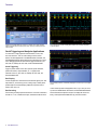
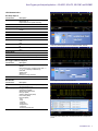
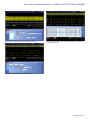
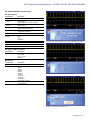
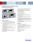
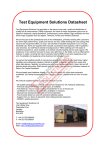
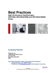
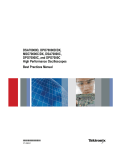
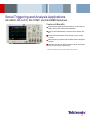
Serial Triggering and Analysis Applications
SR-AERO, SR-AUTO, SR-COMP, and SR-EMBD Datasheet
Features & Benefits
Automated Serial Triggering and Decode Options for I2C, SPI, CAN, LIN,
FlexRay, MIL-STD-1553, and RS-232/422/485/UART*1
Trigger on all the critical elements of a serial bus such as address, data,
etc.
Decode all the critical elements of each message. No more counting
1s and 0s!
Search through long acquisitions with user-defined criteria to find specific
messages
Event Table shows decoded serial bus activity in a tabular, time-stamped
format for quick summary of system activity
*1 USB, Ethernet, and MIPI® D-PHY support information available in separate data sheets.
Datasheet
Triggering on a specific address on an I2C bus. A complete set of triggers, including
triggers for specific address and data packet content, ensures you quickly capture your
event of interest.
Color-coded display of I2C bus, showing Start, Address, Data, and Stop components
of the serial signal.
Serial Triggering and Analysis Applications
On a serial bus, a single signal often includes address, control, data,
and clock information. This can make isolating events of interest
difficult. The Serial Applications for the MSO/DPO5000, DPO7000C, and
DPO/DSA/MSO70000C/D Series transform the oscilloscopes into a robust
tool for debugging serial buses with automatic trigger and decode for I2C,
SPI, CAN, LIN, FlexRay, MIL-STD-1553, and RS-232/422/485/UART.
Serial Triggering
Trigger on packet content such as start of packet, specific addresses,
specific data content, unique identifiers, etc. on popular serial
interfaces such as I2C, SPI, CAN, LIN, FlexRay, MIL-STD-1553, and
RS-232/422/485/UART.
Bus Display
Provides a higher-level, combined view of the individual signals (clock, data,
chip enable, etc.) that make up your bus, making it easy to identify where
packets begin and end and identifying subpacket components such as
address, data, errors, etc.
Bus Decoding
Tired of having to visually inspect the waveform to count clocks, determine if
each bit is a 1 or a 0, combine bits into bytes, and determine the hex value?
2
www.tektronix.com
Decoded display of SPI bus, automatically displaying bus content in any of several digital
formats.
Let the oscilloscope with a serial application do it for you! Once you’ve set
up a bus, the MSO/DPO5000, DPO7000C, and DPO/DSA/MSO70000C/D
Series will decode each packet on the bus, and display the value in hex,
binary, or ASCII (RS-232/422/485/UART only) in the bus waveform.
Serial Triggering and Analysis Applications — SR-AERO, SR-AUTO, SR-COMP, and SR-EMBD
Event Table display of bus content, with time stamp information for each packet.
Event Table
In addition to seeing decoded packet data on the bus waveform itself, you
can view all captured packets in a tabular view much like you would see in
a software listing. Packets are time stamped and listed consecutively with
columns for each component (Address, Data, etc.).
Search
Serial triggering is very useful for isolating the event of interest, but once
you’ve captured it and need to analyze the surrounding data, what do
Serial Search display showing every occurrence of the specified serial event.
you do? In the past, users had to manually scroll through the waveform
counting and converting bits and looking for what caused the event. With
a Serial Application, you can enable the MSO/DPO5000, DPO7000C,
or DPO/DSA/MSO70000C/D Series oscilloscope to automatically search
through the acquired data for user-defined criteria including serial packet
content. Each occurrence is highlighted by a search mark. Rapid navigation
between marks is as simple as pressing the Previous (←) and Next (→)
buttons on the oscilloscope front panel.
www.tektronix.com
3
Datasheet
Characteristics
I2C Characteristics
Bus Setup Options
Characteristic
Description
I2C Sources (Clock and
Data)
Analog channels 1-4
Math channels 1-4
Digital channels D0 - D15 (MSO models only)
Per-channel thresholds
Single ended
Yes or No
Hex
Binary
Thresholds
Recommended Probing
Include R/W in Address
Address/Data Formats
Available
Display Modes
Bus
Bus and Waveforms
Event Table
Bus only
Simultaneous display of bus and digital waveforms
Decoded packet data in a tabular view
I2C bus setup, showing assignment of source signals and digital thresholds.
Bus Trigger and Search Options
Characteristic
Description
Trigger and/or Search On Start
Stop
Repeated Start
Missing Ack
Address (7 or 10 bit)
Data (1-5 bytes)
Address and Data
Bus Decode
Characteristic
Description
Maximum Clock/Data
Rate
Decode Display
Up to 10 Mb/s (automatic selection)
Start (green bar)
Address (yellow packet)
Missing Ack (! symbol)
Data (cyan packet)
Stop (red bar)
Color-coded I2C bus display, using hexadecimal display format.
Triggering on a specific address value on the I2C bus.
4
www.tektronix.com
Serial Triggering and Analysis Applications — SR-AERO, SR-AUTO, SR-COMP, and SR-EMBD
SPI Characteristics
Bus Setup Options
Characteristic
Description
SPI Sources (Clock,
Data, and Slave Select)
Analog channels 1-4
Math channels 1-4
Digital channels D0 - D15 (MSO models only)
Per-channel thresholds
Single ended
Thresholds
Recommended Probing
Decode Configuration
Framing
Clock
Slave Select
Data
Word Size
Bit Order
Formats Available
Idle Time (2-wire SPI)
Slave Select (3-wire SPI)
Rising or Falling Edge
Active High or Active Low
Active High or Active Low
4 - 32 bits
Most Significant (MS) First
Least Significant (LS) First
Hex
Binary
SPI bus setup, showing assignment of source signals and digital thresholds.
Display Modes
Bus
Bus and Waveforms
Event Table
Bus only
Simultaneous display of bus and digital waveforms
Decoded packet data in a tabular view
Bus Trigger and Search Options
Characteristic
Description
Trigger and/or Search On SS
Data (1 - 16 bytes)
Bus Decode
Characteristic
Description
Maximum Clock/Data
Rate
Decode Display
Up to 10 Mb/s (automatic selection)
Start (green bar)
Data (cyan packet)
Stop (red bar)
Color-coded SPI bus display, showing binary display format.
Triggering on a specific data value on the SPI bus.
www.tektronix.com
5
Datasheet
CAN Characteristics
Bus Setup Options
Characteristic
Description
Analog channels 1-4
Source for CAN_H,
CAN_L, Rx, or Tx Probing Math channels 1-4
Digital channels D0 - D15 (MSO models only)
Analog channels 1-4
Source for Differential
Math channels 1-4
Probing
Thresholds
Per-channel thresholds
Recommended Probing
CAN_H, CAN_L, Rx, Single ended
Tx
Differential
Differential
Bit Rate
Predefined list of rates 10 Kb/s - 1 Mb/s
Custom
10 Kb/s - 1 Mb/s
Sample Point
50% of bit period or unit interval
Formats Available
Hex
Binary
CAN bus setup, showing assignment of source, threshold, and bit rate.
Display Modes
Bus
Bus and Waveforms
Event Table
Bus only
Simultaneous display of bus and digital waveforms
Decoded packet data in a tabular view
Bus Trigger and Search Options
Characteristic
Description
Trigger and/or Search On Start of Frame
Type of Frame (Data, Remote, Error, Overload)
Identifier (Standard or Extended)
Data (number of bytes 1-8, trigger or search when =,
!=, <, >, <=, >=)
Identifier and Data
EOF
Missing Ack
Bit Stuff Error
Bus Decode
Characteristic
Description
Maximum Clock/Data
Rate
Decode Display
Up to 1 Mb/s (for automated decoding of bus)
Triggering on a specific ID and data value on the CAN bus.
Start (green bar)
Identifier (yellow packet)
DLC, CRC (blue packet)
Missing Ack (red ! symbol)
Data (cyan packet)
Stop (red bar)
Errors (red packet)
Protocol Decode Event Table provides a time-stamped, tabular view of all captured
packets on the CAN bus.
6
www.tektronix.com
Serial Triggering and Analysis Applications — SR-AERO, SR-AUTO, SR-COMP, and SR-EMBD
LIN Characteristics
Bus Setup Options
Characteristic
Description
LIN Source
Analog channels 1-4
Math channels 1-4
Digital channels D0 - D15 (MSO models only)
Per-channel thresholds
Single ended
Normal
Inverted
Thresholds
Recommended Probing
Polarity
Bit Rate
Predefined list of rates
Custom
Sample Point
LIN Standard
1.2 Kb/s - 19.2 Kb/s
800 b/s - 100 Kb/s
50% of bit period or unit interval
V 1.x
V 2.x
Both
Include Parity Bits with ID Yes
No
Formats Available
Decimal: ID and Parity; Hex: Data and Checksum
Binary
LIN bus setup, showing assignment of source, thresholds, standard, and bit rate.
Display Modes
Bus
Bus and Waveforms
Event Table
Bus only
Simultaneous display of bus and digital waveforms
Decoded packet data in a tabular view
Bus Trigger and Search Options
Characteristic
Description
Trigger and/or Search On Sync
Identifier
Data (number of bytes 1-8, trigger or search when =, !=,
<, >, <=, >=, Inside Range, Outside Range)
ID and Data
Wakeup Frame
Sleep Frame
Error (Sync, ID Parity, Checksum)
Bit Rate
800 b/s - 19.2 Kb/s
LIN bus trigger setup, capturing a specified data value.
Bus Decode
Characteristic
Description
Maximum Clock/Data
Rate
Decode Display
Up to 100 Kb/s, by LIN definition up to 20 Kb/s (for
automated decoding of bus)
Start (green bar)
Sync, Break (blue packet)
Identifier, Parity (yellow packet)
Data (cyan packet)
Checksum, Wakeup (blue packet)
End of Frame (red bar)
Errors (red packet)
- Sync
- Parity
- Checksum
- Header Time
- Response Time
- Frame Time
- Response and Frame Time
Protocol Decode Event Table provides a time-stamped, tabular view of all captured LIN
packets.
www.tektronix.com
7
Datasheet
FlexRay Characteristics
Bus Trigger and Search Options
Characteristic
Bus Setup Options
Description
Characteristic
Description
Source for Differential
Probing (Bdiff)
Source for Single-ended
Probing (BP, BM)
Analog channels 1-4
Math channels 1-4
Analog channels 1-4
Math channels 1-4
Digital channels D0 - D15 (MSO models only)
Analog channels 1-4
Math channels 1-4
Digital channels D0 - D15 (MSO models only)
Trigger and/or Search On Start of Frame
Indicator Bits (Normal, Payload, Null, Sync, Startup)
Cycle Count (when =, !=, <, >, <=, >=)
Header Fields (Indicator Bits, Identifier, Payload Length,
Header CRC, and Cycle Count)
Identifier (when =, !=, <, >, <=, >=)
Data (when =, !=, <, >, <=, >=)
Identifier and Data
End Of Frame (Static, Dynamic)
Error (Header CRC, Trailer CRC, NULL Frame in Static,
NULL Frame in Dynamic, Sync Frame in Dynamic, Start
Frame No Sync)
High and Low thresholds
High and Low thresholds
Bus Decode
Source for Single-ended
Probing (Tx, Rx)
Thresholds
Bdiff
BP, BM (analog and
math channels)
BP, BM (digital
channels)
Tx, Rx
Recommended Probing
Bdiff, BP, BM
Rx, Tx
Channel Type
Bit Rate
Predefined list of rates
Custom
Formats Available
Single threshold
Single threshold
Differential
Single ended
A or B
2.5 Mb/s, 5 Mb/s, 10 Mb/s
1 Mb/s - 10 Mb/s
Hex
Binary
Mixed (Decimal: ID, Len, and Count; Hex: CRCs and
Data)
Display Modes
Bus
Bus and Waveforms
Event Table
8
www.tektronix.com
Bus only
Simultaneous display of bus and digital waveforms
Decoded packet data in a tabular view
Characteristic
Description
Maximum Clock/Data
Rate
Decode Display
Up to 10 Mb/s (for automated decoding of bus)
TTS (purple box)
Start (green bracket)
Frame ID (yellow box)
Payload Length (purple box)
Headers (purple box)
- Null
- Normal
- Sync
- Payload
- Startup
- Unknown
- Null Sync
- Payload Sync
- Null Startup
- Payload Startup
- CRC
Cycle Count (yellow box)
Data (cyan box)
CRC, DTS, CID (purple box)
Stop (red bracket)
- TSS
- Header CRC
- Trailer CRC
- Null Frame
- Sync Frame
- Startup Frame
- BSS
- FSS
Serial Triggering and Analysis Applications — SR-AERO, SR-AUTO, SR-COMP, and SR-EMBD
FlexRay bus setup, showing assignment of source, threshold, and bit rate.
Protocol Decode Event Table provides a time-stamped, tabular view of all captured
packets on the FlexRay bus.
Triggering on a specific Identifier value on the FlexRay bus.
www.tektronix.com
9
Datasheet
MIL-STD-1553 Characteristics
Bus Setup Options
Characteristic
Description
Source
Analog channels 1-4
Math channels 1-4
High and Low thresholds
Differential or Single-ended (only one single-ended
signal required)
Normal or Inverted
1 Mb/s, per the standard
Hex
Binary
Mixed: Hex (data), Decimal (addresses and count)
Thresholds
Recommended Probing
Polarity
Bit Rate
Formats Available
Display Modes
Bus
Bus and Waveforms
Event Table
Bus only
Simultaneous display of bus and digital waveforms
Decoded packet data in a tabular view
MIL-1553 bus setup, showing dual threshold settings.
Bus Trigger and Search Options
Characteristic
Description
Trigger and/or Search On Sync
Command Word*2 (set RT Address (=, !=, <, >, <=, >=),
T/R, Sub-address/Mode, Data Word Count/Mode Code,
and Parity individually)
Status Word*2 (set RT Address (=, !=, <, >, <=, >=),
Message Error, Instrumentation, Service Request Bit,
Broadcast Command Received, Busy, Subsystem Flag,
Dynamic Bus Control Acceptance (DBCA), Terminal
Flag, and Parity individually)
Data Word (user-specified 16-bit data and parity
values)
Idle Time (minimum time selectable from 2 µs to
100 µs; maximum time selectable from 2 µs to 100 µs;
trigger on < minimum, > maximum, inside range,
outside range)
Error (Sync, Parity, Manchester, Noncontiguous Data)
Bus Decode
Characteristic
Description
Maximum Clock/Data
Rate
Decode Display
Up to 1 Mb/s (for automated decoding of bus)
Triggering on a specific data value on the MIL-STD-1553 bus.
Start (green bar)
Sync*3 (purple box) with Word Type (Command, Status,
Data) identified
Address (yellow box)
R/T (purple box)
Word Count (purple box)
Status Bits (purple box)
Data (cyan box)
Parity (purple box)
Stop (red bar)
Errors (red box)
*2 Trigger selection of Command Word will trigger on Command and ambiguous Command/Status words.
Trigger selection of Status Word will trigger on Status and ambiguous Command/Status words.
*3 Ambiguous Command and Status words will be labeled with C/S and a generic bit decode will be displayed.
Protocol Decode Event Table for MIL-STD-1553 bus with all captured packets time
stamped and in a tabular view.
10
www.tektronix.com
Serial Triggering and Analysis Applications — SR-AERO, SR-AUTO, SR-COMP, and SR-EMBD
RS-232/422/485/UART Characteristics
Bus Setup Options
Characteristic
Sources
RS-232
UART
RS-422
RS-485
Polarity
Recommended Probing
Number of Bits
Address/Data Formats
Available
Description
Analog channels 1-4
Math channels 1-4
Digital channels D0 - D15 (MSO models only)
Analog channels 1-4
Math channels 1-4
Normal (RS-232)
Inverted (UART, RS-422/RS-485)
RS-232/UART: Single ended
RS-422/RS-485: Differential
7-9
Hex
Binary
ASCII
Packet View
Display Modes
Bus
Bus and Waveforms
Event Table
RS-232 bus setup, showing assignment of source signal, digital threshold, and polarity.
Bus only
Simultaneous display of bus and digital waveforms
Decoded packet data in a tabular view
Bus Trigger and Search Options
Characteristic
Description
Trigger and/or Search On Start
End of Packet
Data (1 - 5 bytes)
Parity Error
Bus Decode
Characteristic
Description
Maximum Bit Rate
Bit Rate Selections
Up to 10 Mb/s (automatic selection)
50 b/s
300 b/s
1200 b/s
2,400 b/s
9,600 b/s
19,200 b/s
38,400 b/s
115,200 b/s
921,600 b/s
10,000,000 b/s
Custom (50 b/s - 10 Mb/s)
Data (cyan packet)
Errors (red packet)
Decode Display
Color-coded RS-232 bus display, showing ASCII display format.
Triggering on a start of packet on the RS-232 bus.
www.tektronix.com
11
Datasheet
Ordering Information
Optional Applications
MSO/DPO5000,
DPO7000C, and
DPO/DSA/MSO70000C/D
Series Option*4
Description
I2C, SPI
SR-EMBD
MIL-STD-1553
SR-AERO
CAN/LIN/FlexRay
SR-AUTO
RS-232/422/485/UART
SR-COMP
Embedded Serial Triggering and Analysis (I2C, SPI). Enables triggering on packet-level information on I2C and
SPI buses as well as analytical tools such as digital views of the signal, bus views, packet decoding, search tools,
and packet decode tables with time stamp information.
Aerospace Serial Triggering and Analysis (MIL-STD-1553). Enables triggering on packet-level information on
MIL-STD-1553 buses as well as analytical tools such as digital views of the signal, bus views, packet decoding,
search tools, and packet decode tables with time stamp information.
Automotive Serial Triggering and Analysis (CAN/LIN/FlexRay). Enables triggering on packet-level information
on CAN/LIN/FlexRay buses as well as analytical tools such as digital views of the signal, bus views, packet
decoding, search tools, and packet decode tables with time stamp information.
Computer Serial Triggering and Analysis (RS-232/422/485/UART). Enables triggering on packet-level information
on RS-232/422/485/UART buses as well as analytical tools such as digital views of the signal, bus views, packet
decoding, search tools, and packet decode tables with time stamp information.
Serial Bus
*4 USB, Ethernet, and MIPI® D-PHY options also available.
Note: Serial Triggering and Analysis application software does not operate on earlier versions of the DPO7000, DPO/DSA70000, or DPO/DSA70000B Series oscilloscopes.
To upgrade an existing*5 MSO/DPO5000, DPO7000C, or
DPO/DSA/MSO70000C/D Series
To order a floating license for an existing*5 MSO/DPO5000,
DPO7000C, or DPO/DSA/MSO70000C/D Series
Serial Bus
Order
Serial Bus
Order
I2C, SPI
CAN, LIN, FlexRay
MIL-STD-1553
RS-232/422/485/UART
DPO-UP Option SR-EMBD
DPO-UP Option SR-AUTO
DPO-UP Option SR-AERO
DPO-UP Option SR-COMP
I2C, SPI
CAN, LIN, FlexRay
MIL-STD-1553
RS-232/422/485/UART
DPOFL-SR-EMBD
DPOFL-SR-AUTO
DPOFL-SR-AERO
DPOFL-SR-COMP
Note: Software is supplied on the internal hard drive of the MSO/DPO5000, DPO7000C, and
DPO/DSA/MSO70000C/D Series oscilloscopes. User documentation (online or user manual) is part of the
oscilloscope documentation.
*5 Also update oscilloscope firmware to latest version, available for free download from www.tektronix.com.
Recommended Probes
Please refer to www.tek.com/probes for further information on the recommended
models of probes and any necessary probe adapters.
Tektronix is registered to ISO 9001 and ISO 14001 by SRI Quality System Registrar.
12
www.tektronix.com
Serial Triggering and Analysis Applications — SR-AERO, SR-AUTO, SR-COMP, and SR-EMBD
www.tektronix.com
13
Datasheet
14
www.tektronix.com
Serial Triggering and Analysis Applications — SR-AERO, SR-AUTO, SR-COMP, and SR-EMBD
www.tektronix.com
15
Datasheet
Contact Tektronix:
ASEAN / Australasia (65) 6356 3900
Austria 00800 2255 4835*
Balkans, Israel, South Africa and other ISE Countries +41 52 675 3777
Belgium 00800 2255 4835*
Brazil +55 (11) 3759 7627
Canada 1 800 833 9200
Central East Europe and the Baltics +41 52 675 3777
Central Europe & Greece +41 52 675 3777
Denmark +45 80 88 1401
Finland +41 52 675 3777
France 00800 2255 4835*
Germany 00800 2255 4835*
Hong Kong 400 820 5835
India 000 800 650 1835
Italy 00800 2255 4835*
Japan 81 (3) 6714 3010
Luxembourg +41 52 675 3777
Mexico, Central/South America & Caribbean 52 (55) 56 04 50 90
Middle East, Asia, and North Africa +41 52 675 3777
The Netherlands 00800 2255 4835*
Norway 800 16098
People’s Republic of China 400 820 5835
Poland +41 52 675 3777
Portugal 80 08 12370
Republic of Korea 001 800 8255 2835
Russia & CIS +7 (495) 7484900
South Africa +41 52 675 3777
Spain 00800 2255 4835*
Sweden 00800 2255 4835*
Switzerland 00800 2255 4835*
Taiwan 886 (2) 2722 9622
United Kingdom & Ireland 00800 2255 4835*
USA 1 800 833 9200
* European toll-free number. If not accessible, call: +41 52 675 3777
Updated 10 February 2011
For Further Information. Tektronix maintains a comprehensive, constantly expanding
collection of application notes, technical briefs and other resources to help engineers working
on the cutting edge of technology. Please visit www.tektronix.com
Copyright © Tektronix, Inc. All rights reserved. Tektronix products are covered by U.S. and foreign patents,
issued and pending. Information in this publication supersedes that in all previously published material.
Specification and price change privileges reserved. TEKTRONIX and TEK are registered trademarks of
Tektronix, Inc. All other trade names referenced are the service marks, trademarks, or registered trademarks
of their respective companies.
19 Dec 2012
www.tektronix.com
48W-26149-5