1
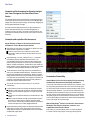
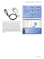
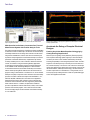
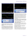
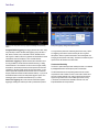
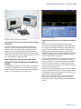
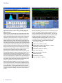
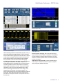
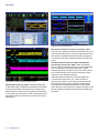
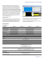
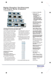
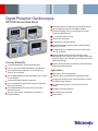
Digital Phosphor Oscilloscopes
DPO7000 Series Data Sheet
Event Search and Mark to Find Specific Events in the Entire Waveform
Pinpoint® Triggering provides the Most Flexible and Highest
Performance Triggering, with Over 1400 Combinations to Address
Virtually Any Triggering Situation.
12.1” XGA Display with Touch Screen
Communications Mask Testing
Clock Recovery from Serial Data Streams
64-bit NRZ Serial Pattern Trigger for Isolation of Pattern-dependent
Effects up to 1.25 Gb/s
Low-speed Serial Protocol Triggering and Decode (I2C, SPI, RS-232,
CAN, LIN, and FlexRay)
Features & Benefits
3.5 GHz Bandwidth Model for Serial and Digital Applications
Technology-specific Software Solutions provide Built-in Domain
Expertise for MIPI® D-PHY, Ethernet, USB 2.0 Compliance Testing, Jitter,
Timing, Eye Diagram, Power, DDR Memory Bus Analysis, CAN, LIN, and
FlexRay Network Design
OpenChoice® Software with Microsoft Windows XP OS enables Built-in
Networking and Extended Analysis
2.5 GHz, 1 GHz, and 500 MHz Bandwidth Models for All Applications
Up to 40 GS/s Real-time Sample Rate on One Channel and up to
10 GS/s on All Four Channels
Up to 500 Megasamples Record Length with MultiView Zoom™ Feature
for Quick Navigation
>250,000 wfms/s Maximum Waveform Capture Rate
Up to 310,000 Waveforms per Second with FastFrame™ Segmented
Memory Acquisition Mode
User-selectable Bandwidth Limit Filters for Better Low-frequency
Measurement Accuracy
MyScope® Custom Windows and Right Mouse Click Menus for
Exceptional Efficiency
Applications
Signal Integrity, Jitter, and Timing Analysis
Verification, Debug, and Characterization of Sophisticated Designs
Debugging and Compliance Testing of Serial Data Streams for Telecom
and Datacom Industry Standards
Low-speed Serial Bus Design (I2C, SPI, RS-232, CAN, LIN, and
FlexRay)
Investigation of Transient Phenomena
Power Measurements and Analysis
Spectral Analysis
Data Sheet
Unmatched Performance for Greater Insight
Into Your Design to Get Your Work Done
Faster
The DPO7000 Series are the new generation of real-time digital phosphor
oscilloscopes and are the industry’s best solution to the challenging signal
integrity issues faced by designers verifying, characterizing, debugging, and
testing sophisticated electronic designs.
The family features exceptional performance in signal acquisition and
analysis, operational simplicity, and unmatched debugging tools to
accelerate your day-to-day tasks. The largest screen in the industry and
the intuitive user interface provide easy access to the maximum amount of
information.
Unmatched Acquisition Performance
User-selectable bandwidth limiting choices.
Signal Fidelity of Tektronix Oscilloscopes Ensures
Confidence in Your Measurement Results
High sample rate on all models, on all channels, to capture more signal
details (transients, imperfections, fast edges)
40 GS/s on one channel on the 2.5 GHz and 3.5 GHz models
Option 2SR to double the maximum real-time sample rate for the
1 GHz model
High bandwidth up to 3.5 GHz, matched across 2, 3, or 4 channels
and enabled by Tektronix proprietary DSP enhancement. The
user-selectable DSP filter on each channel provides magnitude and
phase correction plus extension to 3.5 GHz for more accurate signal
fidelity for complex measurements. The DSP filter on each channel can
also be switched off to take advantage of true 2.5 GHz analog bandwidth
for applications needing the highest available raw data capture.
The DPO7000 Series oscilloscopes include as a standard feature a
series of user-selectable bandwidth limit filters. These filters preserve
the instrument’s bandwidth roll-off characteristics, flatness, and phase
linearity within the new frequency range, thereby reducing the effects of
out-of-band noise on measurements. Now, designers can purchase one
instrument for their highest bandwidth needs and easily optimize it to
handle lower-frequency measurements as well.
Very low jitter noise floor and vertical accuracy for very accurate
measurements
Long acquisition to provide more resolution and longer time sequence
Standard 10 million data points per channel on the DPO7000 Series
Optional up to 500 million total data points on 2.5 GHz and 3.5 GHz
models
Optional up to 250 million total data points on the 500 MHz and 1 GHz
models
Easily manage this deep record length, provide detailed comparison
and analysis of multiple waveform segments with the MultiView
Zoom™ feature. Automatically scroll through deep records visually, or
create a math expression to instantly highlight differences
Highest-performance probing solutions for differential and single-ended
voltage signals as well as current measurement, because accurate
design verification depends on high-bandwidth access to critical signals
and high-fidelity signal capture
2
www.tektronix.com
Zoom in on four areas of interest simultaneously to compare them.
Unmatched Versatility
Get the Most of Your Oscilloscope by Fully Controlling
its Waveform Acquisition and Display Parameters
You have the choice of three horizontal time base modes of operation. If you
are simply doing signal exploration and want to interact with a lively signal,
you will use the Automatic or interactive default mode that provides you with
the liveliest display update rate. If you want a precise measurement and
the highest real-time sample rate that will give you the most measurement
accuracy, then the Constant Sample Rate mode is for you. It will maintain
the highest sample rate and provide the best real-time resolution. The last
mode is called the Manual mode because it ensures direct and independent
control of the sample rate and record length.
With the MyScope® Feature, Create Your Own Control
Windows with Only the Controls, Features, and
Capabilities that You Care About
Easily create your own personalized "toolbox" of oscilloscope features
in a matter of minutes using a simple, visual, drag-and-drop process.
Digital Phosphor Oscilloscopes — DPO7000 Series
3 modes of operation of the horizontal time base.
Tektronix active probes achieve high-speed signal acquisition and measurement fidelity.
Once created, these custom control windows are easily accessed through
a dedicated MyScope button and menu selection on the oscilloscope
button/menu bar, just like any other control window. You can make an
unlimited number of custom control windows, enabling each person who
uses the oscilloscope in a shared environment to have their own unique
control window. MyScope control windows will benefit all oscilloscope
users, eliminating the ramp-up time that many face when returning to the lab
after not using an oscilloscope for a while, and enables the power user to
be far more efficient. Everything you need is found in one control window
rather than having to constantly navigate through menu after menu to repeat
similar tasks.
Drag and drop menu items of interest to create the MyScope control window.
www.tektronix.com
3
Data Sheet
Capture data into Microsoft Excel using the unique Excel toolbar, and create custom
reports using the Word toolbar.
Maximize the probability of capturing elusive glitches and other infrequent events with
FastAcq acquisition mode.
With OpenChoice® Software, Customize Your Test and
Measurement System with Familiar Analysis Tools
The analysis and networking features of OpenChoice software add flexibility
to Windows XP Tektronix oscilloscopes: The Windows XP Remote Desktop
functionality enables remote monitoring of the instrument over the internet.
Using the fast embedded bus, waveform data can be moved directly from
acquisition to analysis applications on the Windows desktop at much faster
speeds than conventional GPIB transfers. Implementation by Tektronix
of industry-standard protocols, such as TekVISA™ interface and ActiveX
controls, are included for using and enhancing Windows applications
for data analysis and documentation. Support for the DPO7000 Series
is also available with NI LabVIEW SignalExpress™ Tektronix Edition.
IVI-COM instrument drivers are included to enable easy communication
with the oscilloscope using GPIB, serial data, and LAN connections from
programs running on the instrument or an external PC. Or, use the Software
Developer’s Kit (SDK) to help create custom software to automate multistep
processes in waveform collection and analysis with Visual BASIC, C, C++,
MATLAB, LabVIEW, LabWindows/CVI, and other common Application
Development Environments (ADE). Integration of the oscilloscope with
external PCs and non-Windows hosts is also supported by the DPO7000
Series software solutions. In addition, the OpenChoice architecture
provides a comprehensive software infrastructure for faster, more versatile
operations. Data transfer programs, such as the Excel or Word toolbar,
are used to simplify analysis and documentation on the Windows desktop
or on an external PC.
Accelerate the Debug of Complex Electrical
Designs
4
www.tektronix.com
FastAcq Acquisition Mode Expedites Debugging by
Clearly Showing Imperfections
More than just color grading, FastAcq enabled by Tektronix proprietary
DPX® acquisition technology captures signals up to more than 250,000
waveforms per second on all 4 channels simultaneously, dramatically
increasing the probability of discovering infrequent fault events. And with a
simple turn of the intensity knob you can clearly see “a world others don’t
see,” because frequency of occurrence is color coded. Some oscilloscope
vendors claim high waveform capture rates for short bursts of time, but only
the DPO7000 Series, enabled by DPX technology, can deliver these fast
waveform capture rates on a sustained basis – saving minutes, hours, or
even days by quickly revealing the nature of faults so sophisticated trigger
modes can be applied to isolate them.
Digital Phosphor Oscilloscopes — DPO7000 Series
Isolate glitches down to 200 ps wide.
Easily trigger on a specific I2C address.
multiple trigger types only on a single event (A event), with delayed trigger
(B event) selection limited to edge-type triggering and often do not provide a
way to reset the trigger sequence if the B event doesn’t occur. But Pinpoint
triggering provides a full suite of advance trigger types on both A and B
triggers with Reset triggering to begin the trigger sequence again after a
specified time, state, or transition so that even events in the most complex
signals can be captured. Other oscilloscopes typically offer less than 20
trigger combinations; Pinpoint triggering offers over 1400 combinations,
all at full performance.
With Enhanced Triggering, you can choose to compensate for the difference
in time there is between the trigger path and the display path and eliminate
virtually any trigger jitter at the trigger point. In this mode, the trigger point
can be used as a measurement reference.
Isolate Setup and Hold violations down to 360 ps.
The Ability to Trigger an Oscilloscope on Events of
Interest is Paramount in Complex Signal Debug and
Validation
Whether you’re trying to find a system error or need to isolate a section
of a complex signal for further analysis, like a DDR Read or Write burst,
Tektronix Pinpoint® triggering provides the solution. The Pinpoint trigger
system uses Silicon Germanium (SiGe) technology to provide trigger
sensitivity of up to the bandwidth of the instrument, and allows selection
of most trigger types on both A and B trigger circuits. It can capture very
narrow glitches with very little trigger jitter. Other trigger systems offer
Trigger on the Most Relevant Bit Sequence of the
Industry-standard Serial Bus
I2C (Inter-Integrated Circuit) triggering is a standard feature and includes
Start Condition, Missing Acknowledge, Restart, Data Read, Address, and/or
Data Frame, in a 10 bit or 7 bit format with a specific selection to choose
whether or not to include the R/W bit.
SPI (Serial Peripheral Interface) triggering is a standard feature and
includes triggering on a data pattern within a user-definable frame.
RS-232 triggering is a standard feature.
CAN (Controller Area Network) triggering is an optional feature (Opt. LSA)
and includes synchronization to the Start or End of a CAN frame on any
CAN high or CAN low signal, triggering on Type of Frame (Data, Remote,
Overload), Identifier, Data, Missing Acknowledge, and Bit Stuffing error.
www.tektronix.com
5
Data Sheet
Triggering on an analog HDTV tri-level sync signal and examining horizontal blanking
interval.
Analog HDTV/EDTV Triggering for emerging standards like 1080i, 1080p,
720p, and 480p as well as standard video triggering on any line within a
field, all lines, all fields, odd or even fields for NTSC, SECAM, and PAL
video signals. In addition, IRE and mV graticules can be selected for easier
measurements and visual inspection. This is a standard feature.
Serial Pattern Triggering for NRZ serial data streams with built-in clock
recovery (available on models DPO7254 and DPO7354 only) to debug
serial architectures. The instrument can recover the clock signal, identify
the transitions, and decode characters and other protocol data. With the
combination of the Serial Trigger and Protocol Decode software, you can
see the captured bit sequences decoded into their words for convenient
analysis (for 8b/10b and other encoded serial data streams), or you can set
the desired encoded words for the serial pattern trigger to capture. This
serial trigger option covers NRZ serial standards up to 1.25 Gb/s.
Pattern Lock Triggering adds a new dimension to NRZ serial pattern
triggering by enabling the oscilloscope to take synchronized acquisitions
6
www.tektronix.com
Serial pattern triggering to debug pattern-dependent issues.
of a long serial test pattern with outstanding time base accuracy. Pattern
lock triggering can be used to remove random jitter from long serial
data patterns. Effects of specific bit transitions can be investigated, and
averaging can be used with mask testing. This feature is included as part of
Option PTM on the DPO7254 and 7354 models.
Unmatched Usability
The TekVPI™ probe interface provides versatility and ease of use enabled
by intelligent bidirectional oscilloscope-to-probe communication.
The DPO7000 Series are fast-responding instruments and contain a
comprehensive suite of features such as a touch screen, shallow menu
structures, intuitive graphical icons, knob-per-channel vertical controls,
support for right mouse clicks, mouse wheel improvements, saving
of waveforms and measurements available in Preview mode, and
Export/Save/Recall menu improvements.
Digital Phosphor Oscilloscopes — DPO7000 Series
Basic spectral UI control window.
An integrated toolset for digital design and troubleshooting.
Interoperability with Logic Analyzers for Digital Design
and Debug
The Tektronix Integrated View (iView™) data display enables digital
designers to solve signal integrity challenges and effectively debug and
verify their systems more quickly and easily. This integration allows
designers to view time-correlated digital and analog data in the same
display window, and isolate the analog characteristics of the digital signals
that are causing systems failures. No user calibration is required. And, once
set up, the iView feature is completely automated.
More Insight into Your Complex Electrical
Design for Characterization and Compliance
Testing
The DPO7000 Series oscilloscopes offer the industry’s most comprehensive
set of analysis and compliance tools, such as a simple math expression,
waveform mask testing, a pass/fail compliance test, event searching, event
marking, or a custom application that you develop yourself.
A Wide Range of Built-in Advanced Waveform Analysis
Tools
Waveform cursors make it easy to measure trace-to-trace timing
characteristics, while cursors that link between YT and XY display modes
make it easy to investigate phase relationships and Safe Operating Area
violations. Select from 53 automatic measurements using a graphical
palette that logically organizes measurements into Amplitude, Time,
Combination, Histogram, and Communications categories. Gather further
insight into your measurement results with statistical data such as mean,
min, max, standard deviation, and population.
Define and apply math expressions to waveform data for on-screen results
in terms that you can use. Access common waveform math functions
with the touch of a button. Or, for advanced applications, create algebraic
expressions consisting of live waveforms, reference waveforms, math
functions, measurement values, scalars, and user-adjustable variables with
an easy-to-use calculator-style editor.
FFT – To analyze your signal in the spectral domain, use the basic spectral
(provides you with the best parameter), or use advanced spectral with the
manual time base horizontal mode (to directly control the frequency span,
center frequency, and resolution bandwidth).
Filtering – Enhance your ability to isolate or remove some important
component of your signal (noise or specific harmonics of the signal) by
creating your own filters, or using the filters provided as standard with the
instrument.
www.tektronix.com
7
Data Sheet
Advanced Analysis, Jitter, Timing, and Eye Diagram Measurements
Accelerating the research of specific events in an acquired waveform.
Advanced Analysis, Jitter, Timing, and Eye Diagram
Measurements
Tight timing margins associated with today’s serial buses demand stable,
low-jitter designs. DPO7000 models include an Essentials version of the
DPOJET software package that extends the oscilloscope’s measurement
capabilities by making measurements over contiguous clock and data
cycles in a single-shot real-time acquisition. DPOJET Essentials adds
multiple measurements, including Time Interval Error, Phase Noise, Skew,
Setup and Hold timing, Duty Cycle, Period, Positive/Negative Width, and
others, and provides the ability to measure key jitter and timing parameters
to help characterize possible system timing issues. Analysis tools such as
plots for time trends and histograms quickly show how timing parameters
change over time, like frequency drift, PLL startup transients, or a circuit’s
response to power supply changes. Spectrum analysis quickly shows the
precise frequency and amplitude of jitter and modulation sources.
Further analysis can be added with DPOJET Advanced (Option DJA) that
offers extended capabilities, providing a complete suite of analysis tools for
insight into jitter and timing as well as other signal quality issues. To the
basic jitter and timing measurements described above, DJA adds advanced
tools such as Rj/Dj separation, eye diagram masks, and Pass/Fail limits for
conformance testing. DPOJET Advanced is the measurement framework
that underlies several other Tektronix standards-specific compliance test
packages for applications such as DDR memory and USB.
Advanced Event Search and Mark – Event Search and Mark will relieve
the user from the tedious task of examining data by highlighting important
events, skipping the unimportant ones, and enhancing the comprehension
of event relationships. You can navigate between the events of interest
effortlessly. Basic event (edge only) search and mark plus support for more
advanced event types like transition, setup and hold, or logic pattern are
available.
Waveform Limit Testing – This feature consists of comparing an acquired
waveform to boundaries. These boundaries are defined by the user to
specify a tolerance band around a reference waveform. If any part of the
acquired waveform falls outside of the limit, the software returns a failure
message and the location of the failure is shown on the waveform.
Communications Mask Testing (Opt. MTM) – This feature provides
a complete portfolio of masks for verifying compliance to serial
communications standards. It supports 156 Standard Masks:
8
www.tektronix.com
ITU-T (64 Kb/s to 155 Mb/s)
ANSI T1.102 (1.544 Mb/s to 155 Mb/s)
Ethernet IEEE 902.3, ANSI X3.263 (125 Mb/s to 1.25 Gb/s)
Sonet/SDH (51.84 Mb/s to 622 Mb/s)
Fibre Channel (133 Mb/s to 2.125 Gb/s)
USB (12 Mb/s to 480 Mb/s)
IEEE 1394 (491.5 Mb/s to 1.966 Gb/s)
RapidI/O (up to 2 Gb/s)
OIF Standards (1.244 Gb/s)
Video (143.18 Mb/s to 1.485 Gb/s)
Digital Phosphor Oscilloscopes — DPO7000 Series
CAN and LIN Timing and Protocol Decode
Power Measurement and Analysis
CAN and LIN Timing and Protocol Decode Software (Opt. LSA) – When you
need to ensure seamless and reliable operation of a CAN or LIN network,
this option enables CAN bus triggering and provides the solution to measure
oscillator tolerance, propagation delay, and simultaneously decode CAN
and LIN messages, with the protocol leveraging the trigger capabilities.
The optional ATM-1 module adds LIN and advanced CAN triggering.
Power Measurement and Analysis (Opt. PWR) – Analyze power dissipation
in power supply switching devices and magnetic components, and
generate detailed reports in customizable formats. The Hi-Res acquisition
mode delivers greater than 8 bits of vertical resolution on single-shot or
repetitive signals at bandwidth up to 125 MHz. The powerful and flexible
measurements, math, and math-on-math capabilities make it an ideal
solution for performing power measurements, such as voltage, current,
instantaneous power, and energy, for power device designers. The
TekVPI™ interface provides smart communication between the oscilloscope
and the probe. TekVPI probe interface also provides more power to the
probe interface, allowing direct connection of current probes to the front of
the oscilloscope.
Ethernet Compliance Testing
USB Compliance Testing
Ethernet Compliance Testing (Opt. ET3) – Receive full physical layer
support for Ethernet variants 10BASE-T, 100BASE-TX, and 1000BASE-T
with the comprehensive, integrated Tektronix Ethernet tool set. Analog
verification, automated compliance software, and device characterization
solutions are all included.
USB Compliance Testing (Opt. USB) – Provides compliance testing for
USB 2.0 signals. A DPO7254 or DPO7354 is required for compliance
testing of high-speed (480 Mb/s) USB signals.
www.tektronix.com
9
Data Sheet
DDR Memory Bus Analysis
UWB WiMedia Analysis and Measurements
MIPI® D-PHY Characterization and Compliance Testing (Opt. D-PHY) –
Verify to the D-PHY specification, rapidly characterize and discover sources
of jitter and signal integrity concerns. Perform high-speed data-clock timing
measurements, along with other electrical characteristics in high-speed or
low-power modes. This option is available on the DPO7254 and DPO7354
models.
Ultra-Wideband Spectral Analysis (Opt. UWB) and Ultra-Wideband
Spectral Analysis Essentials (Opt. UWBE) – UWBE: Ultra-Wideband
Optional MIPI® D-PHY Characterization and Compliance Testing
DDR Memory Bus Analysis (Opt. DDRA) – Automatically identify DDR1,
LP-DDR1 DDR2, DDR3, and GDDR3 Reads and Writes and make JEDEC
conformance measurements with pass/fail results on all edges in every
Read and Write burst. DDRA also provides capabilities for measurements
of clock, address, and control signals. In addition to enabling conformance
testing, DDRA with DPOJET is the fastest way to debug complex memory
signaling issues.
10
www.tektronix.com
microwave, optical, and electrical signals require more real-time bandwidth
than is possible with spectrum analyzer based solutions. Spectral
Analysis and Digital Down Conversion of RF data is fast and easy and the
down-converted frequency span of interest may be exported for further
analysis in tools such as RSAVu and MATLAB.
UWB goes beyond the Essentials version and adds: WiMedia PHY
1.2 analysis with automatic packet, TFC, and data rate detection,
support for all band groups, and Time Frequency Codes and data rates.
Rapid visualization, debug, and report generation of the Spectrograms,
Power Spectral Density, QPSK/DCM Constellations, EVM-vs-Symbol,
EVM-vs-Subcarrier, Common-Phase-Error-vs-Symbol, and Voltage-vs-Time
plots and complete measurements are captured and documented for each
test condition.
Digital Phosphor Oscilloscopes — DPO7000 Series
SignalVu™ Vector Signal Analysis (Opt. SVE, SVP, SVM) – Easily
validate wideband designs and characterize wideband spectral events.
By combining the signal analysis engine of the RSA6100A Real-Time
Spectrum Analyzer with that of the industry’s widest-bandwidth digital
oscilloscopes, you can now evaluate complex signals up to 20 GHz without
the need of an external down converter. You get the functionality of a vector
signal analyzer, a spectrum analyzer, and the powerful trigger capabilities
of a digital oscilloscope – all in a single package. Whether your design
validation needs include wideband radar, high data-rate satellite links, or
frequency-hopping communications, SignalVu™ vector signal analysis
software can speed your time-to-insight by showing you time-variant
behavior of these wideband signals.
SignalVu™ enables detailed analysis in multiple domains.
Floating Licenses
license-key enabled options. To order a floating version of an option license
add “DPOFL-“ prefix to the option name. (e.g. DPOFL-ET3)
Floating licenses offer an alternative method to manage your Tektronix
asset. Floating licenses allow license-key enabled options to be easily
moved among all your DPO/DSA70000B, MSO70000, and DPO7000
Tektronix oscilloscopes. Floating licenses are available for many
Check www.tek.com/products/oscilloscopes/floatinglicenses for additional
information about floating license options.
Characteristics
Vertical System
Characteristic
Input Channels
Bandwidth
(DSP Bandwidth Enhance)
Rise Time
(DSP Bandwidth Enhance)
Hardware Analog
Bandwidth (–3 dB)
Rise Time 10% to 90% (Typical)
Rise Time 20% to 80% (Typical)
DC Gain Accuracy
Bandwidth Limits
Input Coupling
Input Impedance (Software
selectable)
Input Sensitivity
DPO7054
DPO7104
DPO7254
DPO7354
4
500 MHz
1 GHz
2.5 GHz
3.5 GHz*1
460 ps
300 ps
160 ps
115 ps
500 MHz
1 GHz
2.5 GHz
2.5 GHz
Vertical Resolution
Max Input Voltage, 1 MΩ
Max Input Voltage, 50 Ω
Position Range
Offset Range
Offset Accuracy
Delay between any Two
Channels (Typical)
Channel-to-Channel Isolation
(Any two channels at equal
Vertical Scale settings) (Typical)
460 ps
310 ps
300 ps
160 ps
145 ps
200 ps
100 ps
95 ps
±1% with offset/position set to 0
Depending on instrument model: 3.0 GHz, 2.5 GHz, 2 GHz, 1 GHz, 500 MHz, 250 MHz, and 20 MHz
AC, DC, GND
1 MΩ ±1% with 13 pF ±2 pF or
50 Ω ±1%
1 MΩ: 1 mV/div to 10 V/div
50 Ω: 1 mV/div to 1 V/div
8 bit (>11 bit with Hi Res)
±150 V CAT I, derate at 20 dB/decade to 9 VRMS above 200 kHz
5 VRMS, with peaks less than ±24 V
±5 divisions
1 mV/div to 50 mV/div: ±1 V
50.5 mV/div to 99.5 mV/div: ±(1.5 V – 10 divisions)
100 mV/div to 500 mV/div: ±10 V
505 mV/div to 995 mV/div: ±(15 V – 10 divisions)
1 V/div to 5 V/div: ±100 V
5.05 V/div to 10 V/div: ±(150 V – 10 divisions)
1 mV/div to 9.95 mV/div: ±0.2% (offset value-position) ±0.1 div ±1.5 mV
10 mV/div to 99.5 mV/div: ±0.35% (offset value-position) ±0.1 div ±1.5 mV
100 mV/div to 1 V/div: ±0.35% (offset value-position) ±0.1 div ±15 mV
1.01 V/div to 10 V/div: ±0.25% (offset value-position) ±0.1 div ±150 mV
≤100 ps (50 Ω, DC coupling and equal V/div at or above 10 mV/div)
≥100:1 at ≤100 MHz;
≥30:1 between 100 MHz and 2.5 GHz
> 20:1 between 2.5 and 3.5 GHz
*1 3 GHz for sine wave of more than 4 div amplitude (typically).
www.tektronix.com
11
Data Sheet
Time Base System
Characteristic
Time Base Range
with Opt. 2SR
Time Resolution (in ET/IT mode)
with Opt. 2SR
Time Base Delay Time Range
Channel-to-Channel Deskew
Delta Time Measurement Accuracy
Trigger Jitter (RMS)
DPO7054
DPO7104
DPO7254 / DPO7354
50 ps/div to 1000 s/div
—
50 ps/div to 1000 s/div
25 ps/div to 1000 s/div
500 fs
250 fs
5 ns to 250 s
Range ±75 ns
((0.06 / sample rate) + (2.5 ppm × Reading)) RMS
1.5 psRMS (typical) with enhanced triggering OFF
<100 fsRMS with enhanced triggering ON
<1 psRMS (<2 ps peak) for record duration <10 μs (typical)
<2.5 psRMS for record duration <30 ms
<65 parts/trillion for record durations <10 s
±2.5 ppm + Aging <1 ppm per year
25 ps/div to 1000 s/div
—
DPO7054
DPO7104
DPO7254 / DPO7354
20 GS/s
—
20 GS/s
40 GS/s
10 GS/s
20 GS/s
5 GS/s
10 GS/s
4 TS/s (for repetitive signals)
40 GS/s
—
500 fs
—
Jitter Noise Floor
Time Base Accuracy
250 fs
—
Acquisition System
Characteristic
Real-time Sample Rates
1 Channel (Max)
with Opt. 2SR
2 Channels (Max)
with Opt. 2SR
3-4 Channels (Max)
with Opt. 2SR
Equivalent Time Sample Rate (Max)
10 GS/s
—
5 GS/s
—
20 GS/s
—
10 GS/s
—
Maximum Record Length per Channel
Standard Configuration
Record Length Opt. 2RL
Record Length Opt. 5RL
Record Length Opt. 10RL
—
50 M (1-CH), 25 M (2-CH), 12.5 M (4-CH)
125 M (1-CH), 50 M (2-CH), 25 M (4-CH)
250 M (1-CH), 125 M (2-CH), 50 M (4-CH)
—
500 M (1-CH)
250 M (2-CH)
125 M (4-CH)
Maximum Duration at Highest Real-time Resolution (1-CH)
Characteristic
Resolution
with Opt. 2SR
Max Duration with Standard Record
Length and Sample Rate
with Opt. 2SR
Max Duration with Opt. 2RL
with Opt. 2SR
Max Duration with Opt. 5RL
with Opt. 2SR
Max Duration with Opt. 10RL
12
www.tektronix.com
DPO7054
DPO7104
DPO7254 / DPO7354
50 ps (20 GS/s)
—
50 ps (20 GS/s)
25 ps (40 GS/s)
2 ms
25 ps (40 GS/s)
—
2 ms
—
4 ms
—
10 ms
—
—
1 ms
4 ms
2 ms
10 ms
5 ms
—
1 ms
—
2 ms
—
5 ms
—
10 ms
Digital Phosphor Oscilloscopes — DPO7000 Series
Acquisition Modes
Mode
Pinpoint® Trigger System
DPO7054 / DPO7104 / DPO7254 / DPO7354
FastAcq Acquisition Mode FastAcq optimizes the instrument for analysis of
dynamic signals and capture of infrequent events
Maximum FastAcq
>250,000 wfms/s on all 4 channels simultaneously
Waveform Capture Rate
Waveform Database
Accumulate waveform database providing
three-dimensional array of amplitude, time, and counts
Acquire sampled values
Sample
Peak Detect
Captures narrow glitches at all real-time sampling rates:
1/sample rate at ≤10 GS/s
Averaging
From 2 to 10,000 waveforms included in average
Envelope
From 1 to 2×10⁹ waveforms included in min-max
envelope
Hi-Res
Real-time boxcar averaging reduces random noise and
increases resolution
FastFrame™ Acquisition Acquisition memory divided into segments; maximum
trigger rate >310,000 waveforms per second. Time
of arrival recorded with each event. Frame finder tool
helps to visually identify transients
Roll Mode
Scrolls sequential waveform points across the display
in a right-to-left rolling motion. Up to 10 MS/s with a
maximum record length of 40 M
Characteristic
DPO7054 / DPO7104 / DPO7254 / DPO7354
Sensitivity
Internal DC Coupled
External (Auxiliary Input)
1 MΩ
0.7 div DC to 50 MHz increasing to 1.2 div at rated
analog bandwidth (typical); 2.5 div at 3.5 GHz with DSP
bandwidth enhance
250 mV from DC to 50 MHz increasing to 350 mV at
250 MHz (typical)
Trigger Characteristics
A Event and Delayed B
Event Trigger Types
Low-speed Serial
Protocol Trigger Type
(A event only)
Main Trigger Modes
Enhanced Triggering
Trigger Sequences
Communications-related
Triggers
Serial Pattern Trigger
Video-type Trigger
Formats and Field Rates
Clock Recovery System
Clock Recovery Phase
Locked Loop Bandwidth
Frequency Range
Clock Recovery Jitter
(RMS)
Tracking/Acquisition
Range
Minimum Signal
Amplitude Needed for
Clock Recovery
Trigger Level Range
Internal
Aux Trigger
Line
Trigger Coupling
Trigger Holdoff Range
Edge, Glitch, Runt, Width, Transition Time, Time-out,
Pattern, State, Setup/Hold, Window – all except Edge,
Pattern, and State can be Logic State qualified by up
to two channels
I2C, SPI, and RS-232 (standard). CAN bus available
as Opt. LSA.
Trigger on address, data, and special handshaking
states and other conditions
Auto, Normal, and Single
User-selectable; it corrects the difference in timing
between the trigger path and the acquired data path
(it supports all Pinpoint trigger types on both A and
B events except pattern trigger and not available in
FastAcq)
Main, Delayed by Time, Delayed by Events, Reset
by Time, Reset by State, Reset by Transition. All
sequences can include separate horizontal delay after
the trigger event to position the acquisition window in
time
Requires Opt. MTM.
Support for AMI, HDB3, BnZS, CMI, MLT3, and NRZ
encoded communications signals. Select among
isolated positive or negative one, zero pulse form, or
eye patterns as applicable to the standard
On DPO7254 or DPO7354 only, and requires Opt.
PTM.
Up to 64 bit serial word recognizer, bits specified in
binary (high, low, don't care) or hex format. Trigger on
NRZ-encoded data up to 1.25 Gb/s
Triggers from negative sync composite video, field 1,
or field 2 for interlaced systems, any field, specific line,
or any line for interlaced or noninterlaced systems.
Supported systems include NTSC, PAL, SECAM,
and HDTV 1080/24sF, 1080p/25, 1080i/50, 1080i/60,
1080p/24, 720p/60, 480p/60
On DPO7254 or DPO7354 only and requires Opt. PTM
or MTM
Fixed at FBaud/500
1.5 MBaud to 1.25 GBaud
20 psRMS + 1.25% Unit Interval RMS for PRBS data
patterns.
20 psRMS + 1.25% Unit Interval RMS for repeating
"0011” data pattern.
±5% of requested baud (typical)
1 divp-p up to 1.25 GBaud (typical)
±12 divisions from center of screen
TekVPI interface; ±5 V (50 Ω); 150 V CAT I, derate at
20 dB/decade to 9 VRMS above 200 kHz (1 MΩ)
Fixed at 0 V trigger level
DC, AC (attenuates <60 Hz), HF Rej (attenuates
>30 kHz), LF Rej (attenuates <80 kHz), Noise Reject
(reduces sensitivity)
250 ns min to 12 s max
www.tektronix.com
13
Data Sheet
Trigger Modes
Waveform Measurements
Mode
Description
Measurement
Edge
Positive or negative slope on any channel or front-panel
auxiliary input. Coupling includes DC, AC, noise reject,
HF reject, and LF reject
Trigger on or reject glitches of positive, negative, or
either polarity. Minimum glitch width is down to 170 ps
(typical) with rearm time of 250 ps (for DPO7254 or
DPO7354)
Trigger on width of positive or negative pulse either
within or out of selectable time limits (down to 225 ps)
Trigger on a pulse that crosses one threshold but fails to
cross a second threshold before crossing the first again.
Event can be time or logic qualified
Trigger on an event which remains high, low, or either,
for a specified time period. Selectable from 300 ps
Trigger on pulse edge rates that are faster or slower
than specified. Slope may be positive, negative, or
either
Trigger on violations of both setup time and hold time
between clock and data present on any two input
channels
Trigger when pattern goes false or stays true for
specified period of time. Pattern (AND, OR, NAND,
NOR) specified for four input channels defined as high,
low, or don't care
Any logical pattern of channels (1, 2, 3) clocked by edge
on channel 4. Trigger on rising or falling clock edge
Trigger on an event that enters or exits a window
defined by two user-adjustable thresholds. Event can
be time or logic qualified
5 ns to 250 s
1 to 10,000,000 events
Provided as part of Opt. MTM. Support for AMI, HDB3,
BnZS, CMI, MLT3, and NRZ encoded signals
Protocol trigger on DPO7054, DPO7154, DPO7254,
or DPO7354
Basic protocol trigger on DPO7054, DPO7154,
DPO7254, or DPO7354 as part of Opt. LSA. Optional
ATM-1 module adds LIN and advanced CAN triggering
Captures serial data stream with built-in clock recovery
for NRZ standards up to 1.25 Gb/s. Extended with
pattern lock triggering to capture repeated acquisitions
of long serial test patterns
Automatic Measurements 53, of which 8 can be displayed on-screen at any one
time; measurement statistics, user-definable reference
levels, measurement within gates isolating the specific
occurrence within an acquisition to take measurements
on
Amplitude Related
Amplitude, High, Low, Maximum, Minimum,
Peak-to-Peak, Mean, Cycle Mean, RMS, Cycle RMS,
Positive Overshoot, Negative Overshoot
Time Related
Rise Time, Fall Time, Positive Width, Negative Width,
Positive Duty Cycle, Negative Duty Cycle, Period,
Frequency, Delay
Combination
Area, Cycle Area, Phase, Burst Width
Histogram Related
Waveform Count, Hits in Box, Peak Hits, Median,
Maximum, Minimum, Peak-to-Peak, Mean (μ),
Standard Deviation (sigma), μ+1sigma, μ+2sigma,
μ+3sigma
Eye-pattern Related
Extinction Ratio (absolute, %, dB), Eye Height, Eye
Width, Eye Top, Eye Base, Crossing %, Jitter (p-p,
RMS, 6sigma), Noise (p-p, RMS), Signal/Noise Ratio,
Cycle Distortion, Q-Factor
Glitch
Width
Runt
Time-out
Transition
Setup/Hold
Pattern
State
Window
Trigger Delay by Time
Trigger Delay by Events
Comm
I2C, SPI, and RS-232
CAN
Serial Pattern
(Option PTM)
Search and Mark Events
Event
Description
Basic
Mark any events and document waveforms. Search
positive, negative slopes or both on any channels.
Event table summarizes all found events. All events are
time stamped in reference to trigger position. Users can
choose to stop acquisitions when an event is found
Search glitches or runts, as well as transition rate, pulse
width, setup and hold, time-out, window violations,
or find any logic or state pattern on any number of
channels. Search DDR Read or Write bursts with Opt.
DDRA
Advanced
Waveform Processing/Math
Characteristic
Description
Arithmetic
Algebraic Expressions
Add, Subtract, Multiply, Divide Waveforms and Scalars
Define extensive algebraic expressions including
Waveforms, Scalars, User-adjustable Variables, and
Results of Parametric Measurements
e.g. (Integral (CH1 – Mean(CH1)) × 1.414 × VAR1)
Average, Invert, Integrate, Differentiate, Square Root,
Exponential, Log10, Log e, Abs, Ceiling, Floor, Min, Max,
Sin, Cos, Tan, ASin, ACos, ATan, Sinh, Cosh, Tanh
4
Boolean result of comparison >, <, ≥, ≤, ==, !=
Spectral Magnitude and Phase, Real and Imaginary
Spectra
Magnitude: Linear, dB, dBm
Phase: Degrees, radians, group delay
IRE and mV units
Rectangular, Hamming, Hanning, Kaiser-Bessel,
Blackman-Harris, Gaussian, Flattop2, Tek Exponential
As an arbitrary math expression
User-definable filters. Users specify a filter containing
the coefficients of the filter. Filter files provided
A function that generates a Waveform Database
pixmap from a sample waveform. Sample count can
be defined
Math Functions
Math Waveforms
Relational
Frequency Domain
Functions
Vertical Units
Window Functions
Waveform Definition
Filtering Functions
Mask Function
Display Characteristics
Characteristic
Description
Display Type
Display Size
Display Resolution
Waveform Styles
Color Palettes
Liquid-crystal active-matrix color display
Diagonal: 307.3 mm (12.1 in.)
XGA 1240 horizontal × 768 vertical pixels
Vectors, Dots, Variable Persistence, Infinite Persistence
Normal, Green, Gray, Temperature, Spectral, and User
Defined
YT, XY
Display Format
14
www.tektronix.com
Description
Digital Phosphor Oscilloscopes — DPO7000 Series
Computer System and Peripherals
Physical Characteristics
Characteristic
Description
Benchtop Configuration
Operating System
CPU
PC System Memory
Hard Disk Drive
CD/DVD Drive
Mouse
Windows XP
Intel Pentium 4, 3.4 GHz processor
2 GB
Rear-panel, removable hard disk drive, 80 GB capacity
Front-panel CD-R/W, DVD-R drive
Optical wheel mouse, USB interface
Dimension
mm
in.
Height
Width
Depth
292
451
265
11.48
17.75
10.44
Weight
kg
lb.
Net
Shipping
15
28.9
32
63.75
Input/Output Ports
Port
Description
Front Panel
Probe Compensator
Output
Recovered Clock
(for DPO7254 or
DPO7354 only)
Recovered Data (for
DPO7254 or DPO7354
only)
USB 2.0 Port
Aux Trigger Input
Front-panel pins. Amplitude 1 V ±20% into a ≥50 Ω
load; 500 mV from base to top into a 50 Ω load,
frequency 1 kHz ±5%
BNC connector, ≤1.25 Gb/s, Output swing ≥130 mVp-p
into 50 Ω. Requires Option MTM to enable
BNC connector, ≤1.25 Gb/s, Output swing 200 mV into
50 Ω. Requires Option MTM to enable
One USB 2.0 host connector
See trigger specification
Serial Port
VGA Video Port
Oscilloscope VGA Video
Port
Dimension
Height
Width
Depth (from rackmounting
ear to back of instrument)
IEEE 1284, DB-25 connector
Miniature phone jacks
PS-2 compatible
PS-2 compatible
Four USB 2.0 host connectors
RJ-45 connector, supports 10BASE-T, 100BASE-T, and
Gigabit Ethernet
DB-9 COM1 port
DB-15 female connector; connect a second monitor
to use dual-monitor display mode. Supports basic
requirements of PC99 specifications
DB-15 female connector, 31.6 kHz sync, EIA RS-343A
compliant, connect to show the oscilloscope display,
including live waveforms on an external monitor or
projector
mm
in.
331
479
231.75
12.25
18.85
9.12
Weight
kg
lb.
Net
Rackmount Kit
17.4
2.5
37.5
5.5
Mechanical
Cooling – Required Clearance
Dimension
Side Panel
Parallel Port
Audio Ports
Keyboard Port
Mouse Port
USB Ports
LAN Port
Rackmount Configuration
Top
Bottom
Left Side
Right Side
Front
Rear
mm
in.
0
0
76
0
0
0
0
0
3
0
0
0
Rear Panel
Power
100 to 240 VRMS ±10%, 47 to 63 Hz, <550 W
115 VRMS ±10%, 360 to 440 Hz
CAT I, <500 VA
Analog Signal Output
BNC connector provides a buffered version of the signal
that is attached to the CH3 input
Amplitude
50 mV/div ±20% into a 1 MΩ load, 25 mV/div ±20%
into a 50 Ω load
Bandwidth
100 MHz into a 50 Ω load
External Time Base
BNC connector, time base system can phase lock to
Reference In
external 10 MHz reference
Aux Out (Software switchable)
Time base reference BNC connector, provides TTL-compatible output of
out
internal 10 MHz reference oscillator
Trigger output
BNC connector provides a TTL-compatible, polarity
switchable pulse when the oscilloscope triggers
IEEE 488.2 standard
GPIB Port
www.tektronix.com
15
Data Sheet
Option
Environmental
Characteristic
DPO7254/DPO7354 Only
0 °C to +50 °C, excluding CD-R/W drive; +10 °C to
+45 °C, including CD-R/W drive
–40 °C to +71 °C
DPO7104 Only
5% to 95% relative humidity (RH) with a maximum
wet bulb temperature of +29 °C at or below +50 °C,
noncondensing. Upper limit derated to 45% RH above
+30 °C up to +50 °C
5% to 95% relative humidity (RH) with a maximum
wet bulb temperature of +29 °C at or below +60 °C,
noncondensing. Upper limit derated to 45% RH above
+30 °C up to +50 °C
Software Options
Opt. 10RL*5
Temperature
Operating
Nonoperating
Humidity
Operating
Nonoperating
10,000 ft. (3,048 m)
40,000 ft. (12,190 m)
Random Vibration
Operating
Nonoperating
0.000125 G2/Hz from 5 to 350 Hz, –3 dB/octave from
350 to 500 Hz, 0.0000876 G2/Hz at 500 Hz. Overall
level of 0.27 GRMS
0.0175 G2/Hz from 5 to 100 Hz, –3 dB/octave from
100 to 200 Hz, 0.00875 G2/Hz from 200 to 350 Hz,
–3 dB/octave from 350 to 500 Hz, 0.006132 G2/Hz at
500 Hz. Overall level of 2.28 GRMS
Regulatory
Electromagnetic
Compatibility
Certifications
Opt. 2SR*2
Opt.
Opt.
Opt.
Opt.
Opt.
DDRA*9
DJA
ET3*3
HEAC*11
LSA
Opt. MTM
Altitude
Operating
Nonoperating
Description
Description
93/68/EEC; EN61326:1997 +A1 1998+A2:2000
UL 3111-1, CSA1010.1, ISO11469, EN61010-1, IEC
61010-1
Ordering Information
Opt. PWR
Opt. SVE
Opt. SVM*10
Opt. SVP*10
Opt. SVT*10
Opt. TEKEXP
Opt. USB*4
Product
Description
DPO7054
DPO7104
DPO7254
DPO7354
500 MHz Digital Phosphor Oscilloscope
1 GHz Digital Phosphor Oscilloscope
2.5 GHz Digital Phosphor Oscilloscope
3.5 GHz Digital Phosphor Oscilloscope for Serial and
Digital applications
All Models Include: Accessory pouch, front cover, mouse, (4) P6139B 500 MHz,
10x passive probes, quick-start user manual (071-173x-xx), DPO7000 Series
product software media, DPO7000 Series operating system restoration media,
optional applications software media, performance verification procedure PDF file,
GPIB programmer's reference (on product software media), calibration certificate
documenting NIST traceability, Z 540-1 compliance and ISO9001, power cord,
one-year warranty.
Note: User to specify quick-start user manual language, and power plug when
ordering.
(Probes and accessories are not included in the oscilloscope warranty. Refer to the
data sheet for each probe for its unique warranty and calibration terms.)
Options
Double the maximum real-time sample rate to 40 GS/s
(1 channel), 20 GS/s (2 channels), 10 GS/s (3 or
4 channels)
DDR Memory Bus Analysis
DPOJET Jitter and Eye Diagram Analysis – Advanced
TDSET3 Ethernet Compliance Test Software
HEAC Compliance Test Software
Low-speed Serial Analysis includes CAN Trigger, and
CAN/LIN Decode and Analysis
Mask Testing for Serial Communication Standards (up
to 1.5 Gb/s). Includes hardware clock recovery on
DPO7254/DPO7354
DPOPWR Power Measurement and Analysis Software
SignalVu™ Essentials – Vector Signal Analysis
Software
General-purpose Modulation Analysis. Requires Opt.
SVE
Advanced Signal Analysis (including pulse
measurements). Requires Opt. SVE
Frequency and Phase Settling Time Measurements.
Requires Opt. SVE
TekExpress Automation Framework
USB 2.0 Compliance Test Software
DPO7254/DPO7354 Only
Opt. D-PHY*5, 9
Opt. PTM*5
Opt. RTE*5
Opt. UWB*5
DPO7000 Series
500 MS max, 125 MS/Ch
Opt. UWBE*5
MIPI® D-PHY Essentials – Characterization and
Compliance test solution
8b/10b protocol decoding and NRZ serial pattern
triggering. Includes hardware clock recovery up to
1.25 Gb/s and pattern lock triggering
RT-Eye® Serial data compliance and analysis software
Ultra-Wideband Spectral Analysis Software. Includes
WiMedia compliance tests
Ultra-Wideband Spectral Analysis Essentials. Does not
include WiMedia compliance tests
DPO7354 Only
Opt. DVI*8
XGBT*8, 11
Digital Visual Interface compliance test software
10GBASE-T Automation Solution
Bundle Options
Opt. PS1
Power Bundle option includes TPA-BNC adapter, probe
calibration and deskew fixture 067-1686-xx, P5205,
TCP0030, and Opt. PWR
Floating licenses offer an alternative method to manage your Tektronix asset.
Floating licenses allow license-key enabled options to be easily moved among
all your DPO/DSA70000B, MSO70000, and DPO7000 Tektronix oscilloscopes.
Floating licenses are available for many license-key enabled options. To order a
floating version of an option license add “DPOFL-“ prefix to the option name. (e.g.
DPOFL-ET3)
Check www.tek.com/products/oscilloscopes/floatinglicenses for additional
information about floating license options.
*2 DPO7104 only.
*3 Requires Ethernet Test Fixture TF-GBE-ATP or TF-GBE-BTP.
Instrument Options
Option
*4 Requires TDSUSBF (USB Test Fixture). Greater than 2 GHz bandwidth required for high-speed USB.
Description
*5 DPO7254 or DPO7354 only.
Record Length Options
*8 DPO7354 only.
Opt. 2RL
Opt. 5RL
*10 Requires Opt. SVE or SVEM.
16
www.tektronix.com
125 MS max, 25 MS/Ch
250 MS max, 50 MS/Ch
*9 Requires Opt. DJA.
*11 Requires Opt. TEKEXP.
Digital Phosphor Oscilloscopes — DPO7000 Series
User Manual Options
Option
Description
Opt.
Opt.
Opt.
Opt.
Opt.
Opt.
Opt.
Opt.
English manual
French manual
German manual
Japanese manual
Simple Chinese manual
Standard Chinese manual
Korean manual
Russian manual
L0
L1
L3
L5
L7
L8
L9
L10
Power Plug Options
Option
Description
Opt.
Opt.
Opt.
Opt.
Opt.
Opt.
Opt.
Opt.
Opt.
North America
Universal European Union
UK
Australia
Switzerland
Japan
China
India
No power cord
A0
A1
A2
A3
A5
A6
A10
A11
A99
Service Options
(Probes and accessories are not included in the oscilloscope warranty. Refer to the
data sheet for each probe for its unique warranty and calibration terms.)
Option
Description
Opt.
Opt.
Opt.
Opt.
Opt.
Opt.
Calibration Service 3 Years
Calibration Service 5 Years
Calibration Data Report
Calibration Data Report 3 Years (with Opt. C3)
Calibration Data Report 5 Years (with Opt. C5)
Complete Care 3 Years (includes loaner, scheduled
calibration and more)
Complete Care 5 Years (includes loaner, scheduled
calibration and more)
Repair Service 3 Years
Repair Service 5 Years
C3
C5
D1
D3
D5
G3
Opt. G5
Opt. R3
Opt. R5
Recommended Accessories
Probes
Probe
Description
TCP0150
TCP202*6
TDP0500
TDP1000
TDP1500
TDP3500
TAP3500
TAP2500
TAP1500
TCP0030
TPA-BNC
P6139B
20 MHz TekVPI™ AC/DC 150 A current probe
DC coupled current probe
500 MHz TekVPI high-voltage differential probe
1 GHz TekVPI high-voltage differential probe
1.5 GHz TekVPI high-voltage differential probe
3.5 GHz TekVPI high-voltage differential probe
3.5 GHz TekVPI active single-ended probe
2.5 GHz TekVPI active single-ended probe
1.5 GHz TekVPI active single-ended probe
>120 MHz TekVPI AC/DC 30 A current probe
TekProbe-BNC Level 2 to TekVPI adapter
500 MHz, passive probe (four included with each
model)
3 GHz, 20x low C probe
1 GHz differential probe
1 GHz active probe
1.5 GHz active probe
1.5 GHz differential probe
1 GHz high-voltage differential probe
3 GHz differential probe
400 MHz differential probe
1x passive probe 15 MHz
Series current measurement systems
High-voltage differential probes
High-voltage probes
P6158
P6247*6
P6243*6
P6245*6
P6248*6
P6251*6
P6330*6
P6246*6
P6101B
TCPA300/TCPA400*6
P5200/P5205/P5210*6
P5100/P6015A
*6 Probe requires TPA-BNC adapter.
Cables
Cable
Description
GPIB Cable (1 m)
GPIB Cable (2 m)
Centronics Cable
Order 012-0991-01
Order 012-0991-00
Order 012-1214-xx
Accessories
Accessory
Description
Mini Keyboard (USB
Order 119-7083-xx (fits in accessory pouch)
interface)
Keyboard (USB interface) Full-size keyboard with 4 port USB hub. Order
119-6633-00
Transit Case
Order 016-1970-xx
Rackmount Kit
Order 016-1985-xx
Front Hard-drive Option Order 016-1979-xx
for Rackmount Kit
Removable HD Spare
Order 065-0744-xx
Oscilloscope Cart
Order K420 (requires 407-5192-xx bracket set)
WSTRO
WaveStar™ Windows application for remote access
www.tektronix.com
17
Data Sheet
Test Fixtures
Instrument Upgrades
Fixture
Description
TDSUSBF
Probe Calibration/Power
Deskew Fixture
TF-GBE-ATP
Test fixture for use with Opt. USB
Order 067-1686-xx
TF-GBE-BTP
ATM-1
1000/100/10BASE-T Advanced Ethernet Test Package,
includes test fixture, RJ-45 interconnect cable, and
1000BASE-T jitter test channel cable
1000/100/10BASE-T Basic Ethernet Test Package,
includes test fixture and RJ-45 interconnect cable
Advanced CAN and LIN triggering module
Adapters
Adapter
Description
P6701B*6
P6703B*6
Optical/Electrical converter (Multi Mode)
Optical/Electrical converter (Single Mode)
*6 Probe requires TPA-BNC adapter.
Optional Software
Software
Description
PDU-R
PDI-R
PDS-R
PDF-R
SIGEXPTE
Prodigy RS-232/UART decode application
Prodigy I2C decode application
Prodigy SPI decode application
Prodigy FlexRay decode application
NI LabVIEW SignalExpress™ Tektronix Edition
Software (Full Version)
To upgrade your DPO7000 Series oscilloscope, order DPO7UP with option as
noted:
Description
Option
To upgrade record length:
RL02
RL05
RL010*5
From Standard Configuration to Opt. 2RL Configuration
From Standard Configuration to Opt. 5RL Configuration
On DPO7254 or DPO7354 from Standard Configuration
to Opt. 10RL Configuration
From Opt. 2RL Configuration to Opt. 5RL Configuration
On DPO7254 or DPO7354 from Opt. 2RL Configuration
to Opt. 10RL Configuration
On DPO7254 or DPO7354 from Opt. 5RL Configuration
to Opt. 10RL Configuration
RL25
RL210*5
RL510*5
To upgrade DPO7000 Series with:
ASM*12
CP2*7
Advanced Search and Mark
TDSCPM2 ANSI/ITU Telecom pulse compliance testing
software
MIPI® D-PHY Essentials
Opt. DDRA
Opt. DJA
DPOJET Jitter and Eye Diagram Analysis – Essentials
Opt. DVI
Opt. ET3
TDSDDM2 disk drive analysis software
Opt. LSA
Waveform Limit Test
Opt. MTM
To upgrade DPO7254 or DPO7354 with Opt. PTM
Opt. PWR
Opt. RTE or TDSRT eye software
Opt. SVE
Opt. SVM
Opt. SVP
Opt. SVT
Opt. USB
Opt. UWB
Opt. UWBE
D-PHY*5, 9
DDRA*9
DJAM
DJEM*12
DVI*8
ET3*3
J2
LSA
LT*12
MTM
PTM*5
PWR
RTE*5
SVEM
SVM*10
SVP*10
SVT*10
USB*4
UWB*5
UWBE*5
*3 Requires Ethernet Test Fixture TF-GBE-ATP or TF-GBE-BTP.
*4 Requires TDSUSBF (USB Test Fixture). Greater than 2 GHz bandwidth required for high-speed USB.
*5 DPO7254 or DPO7354 only.
*7 Requires Opt. MTM.
*8 DPO7354 only.
*9 Requires Opt. DJA.
*10 Requires Opt. SVE or SVEM.
*12 Included as standard feature on units with serial number above B070000 and C010100.
Product(s) are manufactured in ISO registered facilities.
18
www.tektronix.com
Digital Phosphor Oscilloscopes — DPO7000 Series
www.tektronix.com
19
Data Sheet
Contact Tektronix:
ASEAN / Australasia (65) 6356 3900
Austria 00800 2255 4835*
Balkans, Israel, South Africa and other ISE Countries +41 52 675 3777
Belgium 00800 2255 4835*
Brazil +55 (11) 3759 7600
Canada 1 800 833 9200
Central East Europe, Ukraine, and the Baltics +41 52 675 3777
Central Europe & Greece +41 52 675 3777
Denmark +45 80 88 1401
Finland +41 52 675 3777
France 00800 2255 4835*
Germany 00800 2255 4835*
Hong Kong 400 820 5835
India 000 800 650 1835
Italy 00800 2255 4835*
Japan 81 (3) 6714 3010
Luxembourg +41 52 675 3777
Mexico, Central/South America & Caribbean (52) 56 04 50 90
Middle East, Asia, and North Africa +41 52 675 3777
The Netherlands 00800 2255 4835*
Norway 800 16098
People’s Republic of China 400 820 5835
Poland +41 52 675 3777
Portugal 80 08 12370
Republic of Korea 001 800 8255 2835
Russia & CIS +7 (495) 7484900
South Africa +41 52 675 3777
Spain 00800 2255 4835*
Sweden 00800 2255 4835*
Switzerland 00800 2255 4835*
Taiwan 886 (2) 2722 9622
United Kingdom & Ireland 00800 2255 4835*
USA 1 800 833 9200
* European toll-free number. If not accessible, call: +41 52 675 3777
Updated 25 May 2010
For Further Information. Tektronix maintains a comprehensive, constantly expanding
collection of application notes, technical briefs and other resources to help engineers working
on the cutting edge of technology. Please visit www.tektronix.com
Copyright © Tektronix, Inc. All rights reserved. Tektronix products are covered by U.S. and foreign patents,
issued and pending. Information in this publication supersedes that in all previously published material.
Specification and price change privileges reserved. TEKTRONIX and TEK are registered trademarks of
Tektronix, Inc. All other trade names referenced are the service marks, trademarks, or registered trademarks
of their respective companies.
28 Oct 2010
www.tektronix.com
4MW-19046-19