1
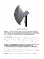
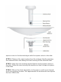
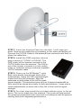
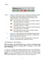
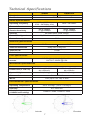
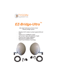
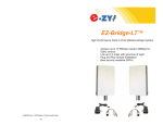
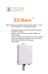
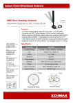
EZ-Bridge-Ultra ™ Ultra High Performance Point to Point Wireless Bridge System ▫ ▫ ▫ ▫ ▫ ▫ Shielded CAT5 cables to protect against EMI and ESD. Achieve up to 150Mbit/sec speed Link up to 8+ miles with good line of sight Plug and Play Simple Installation Best security available (WPA) Field Proven Wireless Technology DANGER! Avoid Powerlines! You Can Be Killed! When following the instructions in this guide to install the antenna take extreme care to avoid contact with overhead power lines, lights and power circuits. Contact with power lines, lights or power circuits may be fatal. We recommend to install antenna no closer than 20 feet from any power lines. Safety: For your own protection, follow these safety rules. ▫ ▫ ▫ ▫ ▫ Perform as many functions as possible on the ground Do not attempt to install the antenna on a rainy, windy or snowy day or if there is ice or snow accumulation at the install site or if the site is wet. Make sure there are no people, pets, etc. below when you are working on a roof or ladder. Watch out for any power lines which may be overhead, underground or behind walls., keeping safely clear of them with the antenna, ladders or any tools. See appendix for FCC RF exposure guidelines Recommended Tools: 13mm Wrench, Screws and screwdriver if mounting to a wall. NOTE: You should be familiar with using tools such as these before attempting installation of the antenna. You should be comfortable with working on a ladder. Getting Started It is recommended that you setup the EZ-Bridge™system in a single room to get acquainted with the operation of the units before installing outdoors. You can just connect the Integrated radio feed to the POE Inserter. You don’t need to mount the feed to the antenna at this stage. Connect 1 EZ-Bridge™ to your router, switch or computer and just power up the other EZ-Bridge™. After powering up each unit, you should be able to communicate with each unit by typing it’s IP address into a standard browser. You can find the IP Address using the Ultradiscovery tool available at EZ-Bridge.com/support Note: We highly recommend connecting the EZ-Bridge™ power supply to a surge protected outlet or an Uninterruptable Power Supply system. We also recommend using only shielded and grounded CAT5 cable between the antenna and the POE Inserter and between the POE Inserter and the router or PC. This will help prevent damage from lightning and electrical surges caused by lightning. 2 Qwik Install STEP 1: Choose a mounting location with good line of sight to the remote location. The unit can be mounted to a pole up to 2.25” diameter or to a wall using the included wall mount brackets. If only short distances are needed the antenna can be mounted inside a building. TECH TIP: Microwaves travel in straight lines and they lose strength quickly when going thru buildings and trees. If there are objects in the microwave path, then useable distance will be reduced. If the target unit is less than 1 mile away then you won’t have to worry too much about a couple obstructions, but if over 1 mile and there are some obstructions in the microwave path, the performance will be reduced. STEP 2: Mount the Antenna—be sure to mount so that the cable hole in the back of the installed plastic housing is pointing down. To mount to a pole: Use the supplied U-Bolt and nuts. Tighten nuts evenly by hand. Set preliminary tilt angles. Use a wrench to fully tighten the nuts. To mount to a wall: Mount the included wall mount bracket to any vertical surface using customer supplied screws or bolts, then mount the EZ -Bridge™ unit to the wall mount bracket. STEP 3: Connect the dish bracket to the dish reflector so that the 3 square cutout in the bracket aligns with the square cutout in the dish. STEP 4: Remove the rear housing from the antenna feed by pressing the release button and sliding the rear housing off the antenna feed. STEP 5: Align the rear housing square feature to the square cutout in the dish. Press the rear housing into position so that it snaps into place in the dish. STEP 6: Mount the dish assembly to the pole or wall mount bracket at the mounting location. Set approximate tilt and azimuth and tighten the two U-Bolt nuts. 4 STEP 7: Insert the Antenna Feed into the dish. It will snap into place. Remove the cable door by pressing on the sides and pulling off. Connect the CAT5/6 Cable to the antenna feed connector and then replace the cable door.. STEP 8: Install the POE inserters indoors near a source of 110VAC to 220VAC. The POE output of the inserter connects to the CAT5/6 cable from the antenna. The LAN input of the inserter connects to a hub, switch, router or computer using a customer supplied CAT5/6 network cable. STEP 8: Power up the EZ-Bridge™ units. Both units should connect with each other automatically. Using the LED signal strength meters built into the antennas, align the antennas on both sides of the link for peak signal strength. The antennas have only an 8 degree beamwidth so they need to be aimed accurately for best performance. It may take a couple adjustments on each side of the link to fine tune the signal strength. STEP 9: As a last step install the included radome cover to the antenna. The cover snaps onto the antenna. This cover will help protect the antenna components from snow and ice buildup as well as prevent nesting birds from degrading performance. 5 Software Settings We strongly recommend that you create a working plug and play link before making ANY changes to the software settings. 1. There is an HTML management system built into every EZ-Bridge™ unit which is accessed thru a standard web browser. The unit can communicate thru the Ethernet cable connection or thru the wireless connection, so you can manage remote units from a single location. NOTE: The device will usually go into a 2minute reboot cycle when APPLYING CHANGES. During this time it will be unresponsive. 6 Technical Specifications Ultra5 Standards Certifications Ultra2-LR 802.11a/n 802.11g/n FCC / CE Radio Specifications Operating Frequency Transmit Power 5170 ~ 5875MHz 2405 ~ 2475MHz 5735 ~ 5875MHz USA 23dBm (250mW) maximum -96 @ 14Mbps -94 @ 14Mbps -75 @ 300Mbps -75 @ 300Mbps 64/128bit WEP, WPA, WPA2 Receive Sensitivity Security Remote Configuration By IP Address; thru Wireless or Ethernet Power Consumption 5.5W Antenna Specifications Antenna Gain 22 dBi Antenna Beamwidth 18 dBi 8 deg Hor / 8 deg Vert Antenna F/B >23dB Polarization Vertical or Horizontal POE Specification Power Over Ethernet Inserter INPUT: 100 – 240VAC @ 50 – 60Hz OUTPUT: 24VDC @ 0.5A Mechanical Specifications Color Dimensions (L x W x H) System Weight White 12.84” dia x 10” (326mm 15.7” dia x 10” (400mm dia x 254mm) dia x 254mm 19 lb (8.6 kg) 20 lb (9.1 kg) Ethernet Connector Shielded RJ45 Mount Pole (up to 2.25” dia) or Wall Environmental Specifications Operating Temperature -22 to 167Deg F (-30 to +75 Deg C) Humidity 0 to 100% RH Wind Loading (125MPH survivability) 100MPH / 23lbs; 125MPH / 35lbs Azimuth Elevation 7 2. IP ADDRESS: The units ship with DHCP enabled so they will try to get their IP Address from your router. The fallback default IP addresses for the EZ-Bridge™ are Unit A 192.168.1.139 and Unit B 192.168.1.239. To access the EZ-Bridge™ your computer IP address must be on the same subnet ie; 192.168.1.xxx. TECH TIP: Download the EZ-Ultra Discovery Tool from http://ezbridge.com/support/support.htm . This tool will assist you in finding the EZ-Bridge-Ultra™ on the network and allow you to access the web control panel of the unit to make any changes. 3. SECURITY: Security is pre-configured with system passwords, WPA2 encryption and Mac Address verification pre-set. This is so that you can setup a plug and play link and have confidence that the link is secure and that your data and network are safe. Once you feel comfortable with the system and its operation, we would recommend the following security changes : a. PASSWORD: Change the user name and password on each side of the link by going to SYSTEM | SYSTEM ACCOUNTS and re-setting the Administrator user name and password. The default is user name = EZTEAM and password = link4me b. ENCRYPTION: Change the WPA2 encryption key by going to WIRELESS then WIRELESS SECURITY . TECH TIP: When setting encryption you must setup both sides of the link to have identical encryption keys. You can setup the remote unit first and then the local unit last in order to be able to configure both units from one location across the wireless link. HEX Encryption keys can use the letters A to F, a to f and numbers 0 to 9. Passphrase keys can use any ASCII characters. The more random the key, the more secure the code. 4. CHANNELS: The default channel is set to Auto. The system will find the best channel each time it reboots. You may want to set a fixed channel if you experience interference from local wireless systems or performance on Auto setting is inadequate. To change the channel go to WIRELESS on Unit A and change the channel frequency. Unit B will follow the channel automatically. 5. TRANSMIT POWER (Tx Power): Normally there wouldn’t be any reason to change the power setting. The factory default setting is 23dBm (250mW) which should be good for most applications. If you have a very short link you will actually get better performance if you turn down the Tx Power to ~20dBm. This is because at close range there is too much power and it has a tendency to overload the input 8 stage of the units and performance degrades. TECH TIP: You may want to play around with different settings to see what works best for your particular link. The measurement you would use to compare settings would be to measure the actual throughput by timing the transfer of data across the link. Under the TOOLS dropdown menu select SPEED TEST. 6. SITE SURVEY: The site survey is a very useful tool to determine what wireless devices are within range of your EZ-Bridge™ and could be a source of interference that could cause degraded performance. Go to the TOOLS drop down menu and then select SITE SURVEY. The list will show all wireless devices and relative signal strength of all the devices within the range of the EZ-Bridge™ . 7. FACTORY DEFAULTS: If at any time the system stops working because of changes made to the settings, you can get back to the original settings by resetting to factory defaults. Go to SYSTEM then RESET TO DEFAULTS. You will need to reset both sides of the link in this way. Always reset the remote unit first and the local unit second. Any customized settings will be lost once this process is initiated. If you cannot access the web page on the unit you can do a manual reset on the antenna feed. You will need to remove the cable door from the back of the antenna and while the unit is powered up press the reset button near the CAT5 cable connector using a paper clip or pin and hold for at least 15 seconds. The LED’s on the side of the antenna will cycle when the unit accepts the reset. Power Cycle or reboot the unit. 8. UPGRADE FIRMWARE: For the latest firmware point your browser to http://ez-bridge.com/support/support.htm Download the latest firmware to your PC. Go to SYSTEM and then UPDATE and then browse for the new files. The EZ-Bridge-Ultra uses 2 different firmwares. Unit A (139) and Unit B (239) use different firmware images so be sure to upload the correct firmware for each individual unit. Caution: If you upload other firmware from different websites and if you reset to defaults, you will lose all the custom settings that make the bridge work properly. Always backup your configuration settings from each antenna before attempting a firmware update. 9. EXPANDING THE NETWORK: You can add additional EZ-BridgeUltra™ units to connect 3 or more buildings together. To add an EZBridge-Ultra™ unit to the existing EZ-Bridge-Ultra network, you set the Wireless mode to STATION , you set the same wireless security, then perform a site survey and connect to the available access point. 10. The units can be used in avariety of other modes but since documentation for the advanced modes is too extensive to cover here 9 please retrieve the documentation online at http://ez-bridge.com/ support/support.htm TECH CORNER Additional Information You May Find Useful 1.RAIN, SNOW, ICE – The frequencies being used by the EZ-Bridge™ will not be affected by heavy rain or falling snow. You should not see any performance degradation due to inclement weather. If snow or ice collects on the front of the antenna, you may see some reduced performance assuming you are shooting a long distance ( >2miles) and the ice or snow buildup is greater than 1” thick on the surface of the antenna. For this reason, we suggest mounting under an eave of a house if feasible for your particular situation. 2.SUN AND HEAT– The EZ-Bridge™ is constructed of all UV protected materials so it will survive for many years in the most extreme of solar environments (ie; an Arizona rooftop during the summer). The unit has been tested and qualified for constant operation at over 167 deg F ambient temperature. Even though the EZ-Bridge™ is designed for long term survivability in extreme environments, we would still recommend that the unit be mounted in a more protected location, like under a roof eave, if possible. Of course, if line of sight is better with the antenna mounted in a non-protected environment then we would recommend the better line of sight mounting location. 3.LIGHTNING – Lightning is the single worst enemy of outdoor electronics equipment. No electronics will survive a direct strike but there are close proximity strikes that can cause huge electrical fields to be generated which can damage electronic equipment. We have taken special care in the design of the EZ-Bridge™ unit to ensure proper grounding of the electronics inside the enclosure to prevent damage from electrical storms. Make sure that the POE Power Supply is plugged into a surge protected outlet such as a surge protected power strip or UPS inside the house. Shielded CAT5 cable is also recommended between the grounded POE Inserter and antenna. 5.PAINTING – The EZ-Bridge™ unit can be painted to match a particular house color. Only non metallic enamel or latex paints should be used. If a paint with metal content is used, it will block the microwaves and cause reduced performance. 6.INTERNET ACCESS SHARING – The EZ-Bridge™ is the perfect equipment to share your internet access with a friend or family member up to 8+ miles away. Using the EZ-Bridge™ provides a seamless connection between networks and you can share the internet access available on the main network with the remote network. Please take note 10 that certain internet service providers may not approve of this and in some cases, they may consider this to be illegal. It’s best before sharing your internet connection that you check with your internet service provider to make sure you aren’t in violation of your service contract. 7.COMMON MICROWAVE BARRIERS – Tinted windows are made by applying a metallized film to the window. If a window has tinting, it will usually block the microwaves and cause reduced performance of the EZ-Bridge™. Concrete walls are also a significant barrier to microwave signals. Aluminum siding on houses is also a barrier to microwave signals. Wood frame houses covered with brick or stucco are pretty transparent to microwave signals and they will reduce the signal strength but the signal will still pass thru the structure. We are bringing this up to you so you can better understand possible causes of performance issues 8.VOICE OVER IP (VOIP) – The EZ-Bridge™ supports all VOIP standards making it possible to use VOIP phones across any EZ-Bridge™ link. Appendix: Federal Communication Commission Interference Statement This equipment has been tested and found to comply with the limits for a Class B digital device, pursuant to Part 15 of the FCC Rules. These limits are designed to provide reasonable protection against harmful interference in a residential installation. This equipment generates, uses and can radiate radio frequency energy and, if not installed and used in accordance with the instructions, may cause harmful interference to radio communications. However, there is no guarantee that interference will not occur in a particular installation. If this equipment does cause harmful interference to radio or television reception, which can be determined by turning the equipment off and on, the user is encouraged to try to correct the interference by one of the following measures: Reorient or relocate the receiving antenna. Increase the separation between the equipment and receiver. Connect the equipment into an outlet on a circuit different from that to which the receiver is connected. Consult the dealer or an experienced radio/TV technician for help. FCC Caution: Any changes or modifications not expressly approved by the party responsible for compliance could void the user's authority to operate this equipment. This device complies with Part 15 of the FCC Rules. Operation is subject to the following two conditions: (1) This device may not cause harmful interference, and (2) this device must accept any interference received, including interference that may cause undesired operation. IMPORTANT NOTE: FCC Radiation Exposure Statement: This equipment complies with FCC radiation exposure limits set forth for an 11 uncontrolled environment. This equipment should be installed and operated with minimum distance 20cm between the radiator & your body. The antenna(s) used for this transmitter must not be co-located or operating in conjunction with any other antenna or transmitter. Limited Warranty All EZ-Bridge products are supplied with a limited 12 month warranty which covers material and workmanship defects. This warranty does not cover the following: ▫ Parts requiring replacement due to improper installation, misuse, poor site conditions, faulty power, etc. ▫ Lightning damage. ▫ Physical damage to the external & internal parts. ▫ Products that have been opened, altered, or defaced. ▫ Water damage for units that were not sealed or mounted according to user manual. ▫ Units that were not properly grounded. ▫ Usage other than in accordance with instructions and the normal intended use. Do not return any products until you receive a Return Material Authorization (RMA) number. Products received without a valid RMA number will be rejected and returned to sender. Warranty Repairs All returns must have a valid RMA number written clearly on the outside of the box. Without an RMA number the shipment will be refused. For customers located in United States and Canada, customer pays all shipping charges incurred to ship the product to Tycon Systems. Tycon Systems pays shipping charges to return the product to the original purchaser. For all other countries, the original purchaser shall pay all shipping, broker fees, duties and taxes incurred in shipping products to and from Tycon Systems. Provided the goods have not been modified or repair attempted by someone other than Tycon Systems, at the option of Tycon Systems, products may be returned either as repaired or replaced. If it is determined that there is no fault found (NFF) on a unit within warranty, the customer will be charged $75 USD for testing time. For products out of warranty, the standard NFF charge is $200. This charge will be at the discretion of Tycon Systems. The RMA number is valid for 14 days from date of issue. The product must be received by the repair depot within these 14days or the shipment may be refused. Shipping and Damage Claims All shipping damage claims are the purchaser's responsibility. Inspect each shipment upon delivery and IMMEDIATELY report all damage, to the carrier. There may be time limits and inspections may be required. 8000038 Rev 1 EZ-Bridge-Ultra Qwik Install Guide 12