1
G4 GRANITERACK iSCSI STORAGE SERVER
Quick Guide
This guide is a quick reference for users to install and operate the G4 GraniteRack and only
provides basic information. For further details on installation and operation, please refer to
the User Manual.
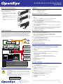
Due to the number and weight of the hard drives, the G4 GraniteRack iSCSI Storage Server
is shipped in two boxes.
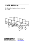
BOX 1 CONTENTS
RACKMOUNT ASSEMBLY INSTRUCTIONS
The box your G4 GraniteRack was shipped in should include two rail assemblies, two rail
mounting brackets, and the mounting screws you will need to install the system into the rack.
There are a variety of rack units available on the market, which may mean the assembly
procedure will differ slightly. Refer to the installation instructions for your model of rack unit.
Please read this section in its entirety before you begin the installation procedure.
Separating the Sections of Rack Rails
1. Extend the rail assembly by pulling it outward.
13
9
56
14
15
16
10
11
7
12
8
1
2
3
4
!
2. Press the quick-release tab.
12
3. Separate the inner rail extension from the
outer rail assembly.
4. Repeat theses steps for the second rail
assembly.
Installing the Inner Rail Extensions
1. Place the inner rail extensions on the side
of the chassis, aligning the hooks of the
chassis with the rail extension holes. Make
sure the extension faces outward, just like
the pre-attached inner rail.
G4 GraniteRack (without drives)
BOX 2 CONTENTS
2. Slide the extension toward the front of the
chassis.
3. Optional: Secure the rail extension to the
chassis with 4 screws (included).
RACKMOUNT RAIL KIT
FRONT BEZEL
4. Repeat these steps for the other side of the
chassis.
Installing the Outer Rack Rails
HARD DRIVES (in boxes, 4 per box)
ACCESSORY BOX
(see contents below)
1. Secure the back end of the outer rail to
the rack using the leaf springs and screws
provided.
2. Press the button where the two outer rails
are joined to retract the smaller outer rail.
3. Hang the hooks of the rails onto the rack
holes and, if desired, use screws to secure
the front of the outer rail onto the rack.
ACCESSORY BOX CONTENTS
4. Repeat these steps for the other outer rail
extension.
NVR CASE KEY
MOUSE
KEYBOARD
Installing the Recorder into a Rack
1. Extend the outer rails
2. Align the inner rails with the outer rails on
the rack.
REPAIR DISK /
SOFTWARE DISK
POWER CABLE
DVI to VGA ADAPTER
3. Slide the inner rails into the outer rails,
keeping pressure even on both sides.
When pushed all the way into the rack,
the rails will click into a locked position
(preventing removal without pressing the
quick-release tabs).
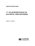
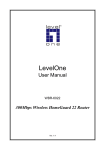
HARD DRIVE INSTALLATION
Your G4 GraniteRack is shipped with the drives in a separate box. To insert the drives, pull
the blue latch release on the front of the drive, insert the drive into the proper port, and close
the latch.
QUICK START GUIDE
CONNECTIONS
Pull blue button to
release latch
Your hard drives should be inserted in order, 1-16, depending on how many hard drives you
have purchased. Each hard drive is marked with the number of its port. See the diagram
below for the order of hard drive ports.
12
No.
Item
No.
Item
No.
Item
1
2
3
4
Power
PS/2 Mouse
PS/2 Keyboard
USB
5
6
7
8
USB
RS-232
VGA
Network
9
10
11
12
Network
RAID Management
Network
RS-232
23221 E Knox Ave
Liberty Lake, WA 99019
1.888.542.1103
FOR UNITS WITH RAID CONFIGURATION ONLY:
Use only identical models to replace the hard drives
Do not re-insert failed drives.
Copyright ©2013 OpenEye. All Rights Reserved. Information contained in this document is subject to change without prior
notice. OpenEye does its best to provide accurate information but cannot be held responsible for typos or mistakes.
32136AB
G4 GRANITERACK iSCSI STORAGE SERVER
Quick Guide
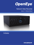
INSTALLING THE FRONT BEZEL
LOGGING IN
If you choose to mount the front bezel onto your
G4 GraniteRack you will need to remove the
attached handles and attach the bezel before
attaching the rackmount rails.
OpenEye recommends changing the username and password for your G4 GraniteRack. The
default Username and Password are as follows
Username: DVRAdmin
2
1
Password: dvr4321
1. Remove the two screws from each handle.
CREATING iSCSI TARGET ACCOUNTS
2. Install the included bezel clips and fasten
with screws.
OpenEye recommends creating a separate target volume for each recorder on your system.
3. Align and slide the right side of the bezel
into the right clip.
1. Click Start > All Programs > Administrative Tools > Microsoft iSCSI Software Target.
2
1
4. Slide the left side of the bezel into the left
clip.
2. Click Yes.
3. Right-click in the Virtual Disk field, and then click Create iSCSI Target.
5. Lock the bezel by turning the key counterclockwise.
4. This will open the iSCSI Target Wizard. Click Next to continue.
5. Type your iSCSI Target Name.
2
1
Note The iSCSI Target Name must consist of lowercase letters and numbers only. No
spaces, special characters, or underscores may be used. For example: n1.3, meaning “NVR1 with 3TB storage.”
6. Type an effective description of the target.
7. Type the IP Address of the recorder you are assigning to this volume in the IQN field,
and then click Next.
Note The iSCSI Qualified Name (IQN) allows the iSCSI target to identify the iSCSI initiator
requesting access. OpenEye recommends using the IP address of the connecting
recorder, but you can also use the MAC address or DNS name.
8. Click Next, and then click Finish.
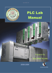
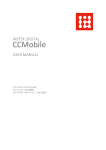
CONNECTION DIAGRAM
A single G4 GraniteRack can be connected to up to 25 network video recorders to provide
up to 64TB of pooled storage.
To connect a G4 GraniteRack to one or more recorders, you can purchase a 24-port switch
from OpenEye. This switch comes preconfigured with Gigabit networking and LACP.
Ports 1-8 are to be used for iSCSI connection. When connecting a G4 GraniteRack, use
2 connections per unit (1 and 2, 3 and 4, 5 and 6, 7 and 8, respectively). Ports 9-16 are to
be used to connect the recorders, and ports 17-24 can be used to connect cameras to the
recorders, if necessary.
CREATING VIRTUAL DISKS
Create a virtual disk for each recorder on your system.
1. In the iSCSI Target window, click Devices.
2. Right-click the Devices List field, and then click Create Virtual Disk.
3. This will open the Create Virtual Disk Wizard. Click Next to continue.
4. Type the location in the File field.
Note The location name should be the same as the iSCSI Target Name. The location should
be formatted as E:\{iSCSI Target name].vhd.
5. Set the Size of the Virtual Disk (in megabits).
6. Type an effective Virtual Disk Description.
7. To assign a recorder client to the volume, click Add.
8. Select the target recorder.
9. Click Next, and then click Finish.
RECORDER CONFIGURATION
Once your G4 GraniteRack is connected and set up, you will need to configure the iSCSI
unit and the recorder to communicate with each other.
CONFIGURE THE GRANITERACK TO COMMUNICATE WITH THE RECORDER
1. On the iSCSI Initiators tab, click Identifier Type, and then select IP Address.
2. Type the IP address of your recorder in the Value field.
3. Click OK.
4. Click OK again.
CONFIGURE THE RECORDER TO COMMUNICATE WITH THE GRANITERACK
1. Restart your recorder in Windows mode.
2. Click Start, and then type iSCSI Initiator in the Search field.
3. Click iSCSI Initiator.
4. In the Target field, type the IP address of your G4 GraniteRack.
5. Click Quick Connect. Once completed, the status will read “connected.”
6. Click Done.
7. Click the Volumes and Devices tab.
8. Click Auto Configure.
9. Click OK.
IP cameras to PoE switch
SET THE VOLUME SIZE
PoE switch to 24-port switch
The volumes you have created on your G4 GraniteRack will be seen by your recorder as
blank hard disks. In order to save video, you must first format the disks.
G4 GraniteRack to 24-port switch
Recorder to 24-port switch
1. Click Disk Management.
24-port switch to recorder
2. In the Initialize Disk window, select GBT.
Note GBT supports drives that are 3TB or larger, providing a large volume size for
maximum storage capacity.
POWER
To reduce the risk of electrical shock or damage to the equipment:
• Do not disable the power grounding plug. The grounding plug is an important safety feature.
• If the electrical plug you are using does not have a ground plug receptacle, contact a licensed electrician to have it replaced with a grounded
electricl outlet.
• Plug the power cord into a grounded electrical outlet that is easily accessible at all times.
• Disconnect the power from the recorder by unplugging the power cord
either from the electrical outlet or the recorder.
Operating Temperature Range
3. Click OK.
4. Right-click Unallocated Volume, and then click New Simple Volume.
5. Click Next.
6. Type the Volume Size (in MB), up to 3TB (3,000,000 MB).
Note OpenEye recommends a maximum volume size of 3TB.
7. Click Next, and then click Next again.
8. Click Allocation Unit Size, and then select 64K.
9. Click Volume Label, and type DVR.
10. Click Next.
11. Click Finish.
32˚F~104˚F (0˚C~40˚C)
23221 E Knox Ave
Liberty Lake, WA 99019
1.888.542.1103
Copyright ©2013 OpenEye. All Rights Reserved. Information contained in this document is subject to change without prior
notice. OpenEye does its best to provide accurate information but cannot be held responsible for typos or mistakes.
32136AB