1
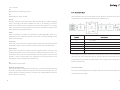
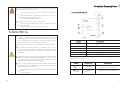
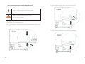
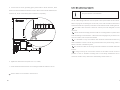
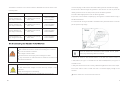
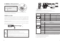
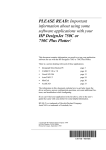
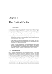
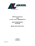
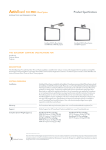
Growatt 10000TL3-US
Growatt 12000TL3-US
Growatt 18000TL3-US
Growatt 20000TL3-US
Installation
GROWATT NEW ENERGY CO., LTD
No . 28 Guangming Road, Shiyan, Baoan District,
Shenzhen, P.R. China
T
F
E
W
+ 86 755 2747 1942
+ 86 755 2747 2131
[email protected]
www.growatt.com
GR - UM - 004 - 02
& Operation Manual
Table
1
Information on this
Document
6
PV Module setting
7
Commissioning
1.1 Validity
1.2 Target Group
1.3 Storage of the manuals
1.4 Additional information
7.1 Display and message
1.5 Symbols in this document
7.2 Operation checking on the
Growatt TL3-US
2
7.3 Two independent MPPT
Safety
2.1 Intended Use
7.4 Communication
2.2 Qualification of skilled person
2.3 Safety instruction
2.4 Operation Warnings
8
Booting and shutdown of the
inverter
8.1 Booting the Growatt TL3-US
3
8.2 Turn off the Growatt TL3-US
Product Description
3.1 Growatt TL3-US
3.2 Type label
3.3 Size and weight
9
Cleaning and Care
3.4 The advantage of the Growatt
9.1 Checking the inverter
TL3-US inverters
9.2 Checking the DC switch
9.3 Cleaning the Inverter
9.4 Cleaning the Fan Guards
4
Unpacking
5
Installation
9.5 Replace fans
10
Decommissioning
5.1 Safety instructions
10.1 Dismantling the Growatt TL3-US
5.2 Selecting the Installation Location
10.2 Packaging the Growatt TL3-US
5.3 Mounting the Growatt TL3-US
10.3 Storage of inverter.
5.4 Electrical Connection
10.4 Disposal
5.5 Grounding
5.6 GRID Type and Grid type
5.7 Growatt TL3-US WIRE BOX
5.8 RS485 Signal Wiring Connections
Information on this Document
11
Trouble Shooting
11.1 Warnings(W)
1
1.1 Validity
11.2 Errors(E)
This manual describes the assembly, installation, commissioning and maintenance of
the following GROWATT inverters:
12
13
14
Specification
Spare Parts and Accessories
Growatt 10000TL3-US
12.1 Specification of the Growatt TL3-US
Growatt 12000TL3-US
12.2 DC Switch information
Growatt 18000TL3-US
12.3 Tripping Limits and Tripping Times
Growatt 20000TL3-US
12.4 Torque Values and Cable Sizes
1.2 Target Group
This manual is for qualified personnel. Qualified personnel have received training
and have demonstrated skills and knowledge in the construction and operation of
this device. Qualified personnel are trained to deal with the dangers and hazards
involved in installing electric devices.
Inverter installation plan
14.1 Single inverter
14.2 Multi inverter
1.3 Storage of the manuals
Keep all Growatt manuals in a safe place for future reference.
15
Contact
1.4 Additional information
You can find further information on special topics in the download area at
www.growatt.com
1
1.5 Symbols in this document
Beware of hot surface
1.5.1 Warnings in this document
The product can become hot during operation. Do not touch the
product during operation.
A warning describes a hazard to equipment or personnel. It calls attention to a
procedure or practice, which, if not correctly performed or adhered to, could result in
damage to or destruction of part or all of Growatt equipment and/or other
equipment connected to the Growatt equipment or personal injury.
Symbol
Observe the operating instructions
Read the product’s documentation before working on it. Follow
all safety precautions and instructions as described in the
documentation.
Description
AC current
DANGER
DANGER indicates a hazardous situation which, if
not avoided, will result in death or serious injury.
WARNING
WARNING indicates a hazardous situation which, if
not avoided, could result in death or serious injury.
CAUTION
CAUTION indicates a hazardous situation which, if
not avoided, could result in minor or moderate injury.
NOTICE
NOTICE is used to address practices not related to
personal injury.
INFORMATION
INFORMATION that you must read and know to ensure
optimal operation of the system.
DC current
Transformerless
1.5.2Markings on this product
Earth Ground
FCC certificate
UL1741 Standard for Safety for Inverters, Converters,
Controllers and Interconnection System Equipment for use with
Distributed Energy Resources. CSA CSA-C22.2 No. 107.1-01 General Use Power Supplies.
Warning regarding dangerous voltage
The product works with high voltage. All work on the product must only
be performed as described in its documentation.
2
3
Safety
2
1.5.3 Glossary
AC
Abbreviation for "Alternating Current”
DC
Abbreviation for "Direct Current”
Energy
Energy is measured in Wh (watt hours), kWh (kilowatt hours) or MWh (megawatt
2.1 Intended Use
The Growatt TL3-US is a PV inverter which converts the direct current of the PV array
to alternating current and feeds it into the power distribution grid.
hours). The energy is the power calculated over time. If, for example, your inverter
operates at a constant power of 20,000 W for half an hour and then at a constant
power of 10,000 W for another half an hour, it has fed 15,000Wh of energy into the
power distribution grid within that hour.
Power
Power is measured in W (watts), kW (kilowatts) or MW (megawatts). Power is an
instantaneous value. It displays the power your inverter is currently feeding into the
Symbol
Description
power distribution grid.
Power rate
Power rate is the radio of current power feeding into the power distribution grid and
the maximum power of the inverter that can feed into the power distribution grid.
Power Factor
Power factor is the ratio of true power or watts to apparent power or volt amps. They
A
PV modules
B
DC load circuit breaker(type 2 wire box no need)
C
Growatt TL3-US Inverter
D
AC load circuit breaker
E
Energy meter
F
Utility grid
are identical only when current and voltage are in phase than the power factor is 1.0.
The power in an ac circuit is very seldom equal to the direct product of the volts and
The Growatt TL3-US takes current from PV array and converts it to alternating
amperes. In order to find the power of a single phase ac circuit the product of volts
current for the power distribution grid (F). Energy surplus may even result in the
and amperes must be multiplied by the power factor.
energy meter (E) of your plant running backwards. The Growatt TL3-US is suitable for
PV
Abbreviation for photovoltaic
indoor and outdoor use.
Wireless communication
The external wireless communication technology is a radio technology that allows
AC circuit breaker
the inverter and other communication products to communicate with each other. The
Each inverter with independent circuit breaker with three or four poles can make sure
external wireless communication does not require line of sight between the devices
to disconnect the grid safely.
and it is selective purchasing.
4
5
Do not share a single circuit breaker with more than one inverter.
CAUTION
Do not connect the any local load between the inverter and the AC
circuit breaker.
PV modules
2.3 Safety instruction
The GROWATT TL3-US Inverters is designed and tested according to international
safety requirements (UL 1741/IEEE 1547); however, certain safety precautions must
be observed when installing and operating this inverter. Read and follow all
instructions, cautions and warnings in this installation manual. If questions arise,
please contact Growatt’s technical services at +86 (0)755 2747 1900.
The PV modules used must be suitable for use with the Growatt TL3-US and must be
approved by the module manufacturer. The PV modules include Monocrystalline silicon
PV modules, polysilicon PV modules, and the thin-film PV modules which with levels of
2.3.1 Assembly Warnings
protection and without connecting to the Ground.
Prior to installation, inspect the unit to ensure absence of any
transport or handling damage, which could affect insulation
integrity or safety clearances; failure to do so could result in safety
hazards.
PV modules with large capacities relative to earth, such as thin-film
Assemble the inverter per the instructions in this manual. Use
care when choosing installation location and adhere to specified
cooling requirements.
PV modules with cells on a metallic substrate, may only be used if their
coupling capacity does not exceed 500 nF.
Do not connecting any PV Modules that the anode or the cathode
needs to connect to the Ground.
Do not connect any energy sources other than PV modules to the
CAUTION
Growatt TL3-US.
Do not connect the any local load between the inverter and the AC
WARNING
Unauthorized removal of necessary protections, improper use,
incorrect installation and operation may lead to serious safety and
shock hazards and/or equipment damage.
In order to minimize the potential of a shock hazard due to
hazardous voltages, cover the entire solar array with dark material
prior to connecting the array to any equipment.
circuit breaker.
The Growatt TL3-US is only used in the Grid-connected system rather
than any other applications.
2.3.2 Electrical Connection Warnings
2.2 Qualification of skilled person
This grid-tied inverter system operates only when properly connected to the AC distribution network. Before connecting the services of Growatt TL3-US to the power
distribution grid, contact the local power distribution grid company. This connection
must be made only by qualified technical personnel to connect, and only after
receiving appropriate approvals, as required by the local authority having
jurisdiction.
6
Make all electrical connections (e.g. conductor termination,
fuses, PE connection, etc.) in accordance with prevailing
regulations. When working with the inverter powered on, adhere to
all prevailing safety regulations to minimize risk of accidents.
WARNING
Systems with inverters typically require additional control (e.g.,
switches, disconnects) or protective devices (e.g., fusing circuit
breakers) depending upon the prevailing safety rules.
7
Product Description
3
The components in the inverter are live. Touching live components
can result in serious injury or death.
DANGER
Do not open the inverter except the wire box by qualified
persons.
Electrical installation, repairs and conversions may only be
carried out by electrically qualified persons.
Do not touch damaged inverters.
3.1 Growatt TL3-US
Danger to life due to high voltages in the inverter
There is residual voltage in the inverter. The inverter takes 20
minutes to discharge
Wait 20 minutes before you open the wire box.
2.4 Operation Warnings
Anytime the inverter has been disconnected from the power
network, use extreme caution as some components can retain
charge sufficient to create a shock hazard; to minimize occurrence
of such conditions, comply with all corresponding safety symbols
and markings present on the unit and in this manual.
Ensure all covers and doors are closed and secure during operation.
All operations regarding transport, installation and start-up,
including maintenance must be operated by qualified, trained
personnel and in compliance with all prevailing codes and
regulations.
WARNING
Although designed to meet all safety requirements, some parts and
surfaces of Inverter are still hot during operation. To reduce the risk
of injury, do not touch the heat sink at the back of the PV-Inverter
or nearby surfaces while Inverter is operating.
Incorrect sizing of the PV plant may result in voltages being present
which could destroy the inverter. The inverter display will read the
error message “PV-Overvoltage!”
Turn the rotary switch of the DC Disconnect to the Off position
immediately.
Contact installer.
8
Symbol
Description
A
LCD
B
LED
C
Wire Box
D
Label
E
Fan air outlet
F
Flying rings
Symbol on the inverter
Symbol
NORMAL
FAULT
Description
Explanation
Tap symbol
Setting the display operation by
tapping the LCD (see Section 4).
Inverter status
symbol
Indicates inverter operation status
9
3.2 Type label
The type labels provide a unique identification of the inverter (The type of product,
Device-specific characteristics, Certificates and approvals). The type labels are on the
right-hand side of the enclosure.
More detail about the type label as the chart below:
Label symbol
Growatt 10000
TL3-US
Growatt 12000
TL3-US
Growatt 18000
TL3-US
Growatt 20000
TL3-US
Range of input
voltage(MPP)
250VDC~600VDC
250VDC~600VDC
250VDC~600VDC
250VDC~600VDC
Max input voltage
600VDC
600VDC
600VDC
600VDC
Max input current
of MPP tracker
21.0ADC/21.0ADC
25.0ADC/25.0ADC
38.0ADC/38.0ADC
42.0ADC/42.0ADC
Max input short
circuit current
32.0ADC/32.0ADC
32.0ADC/32.0ADC
50.0ADC/50.0ADC
50.0ADC/50.0ADC
Nominal output
power
10000W
12000W
18000W
20000W
Nominal grid
voltage
3/N/PE,
277Vac/480Vac
3/N/PE,
277Vac/480Vac
3/N/PE,
277Vac/480Vac
3/N/PE,
277Vac/480Vac
Range of grid
voltage range
422Vac~528Vac
422Vac~528Vac
422Vac~528Vac
422Vac~528Vac
operating grid
frequency
range(HZ)
Min Normal Max
59.3 60.0 60.5
Min Normal Max
59.3 60.0 60.5
Min Normal Max
59.3 60.0 60.5
Min Normal Max
59.3 60.0 60.5
Grid voltage
and frequency
trip times
<150ms
< 150ms
<150ms
<150ms
Max output
current
12.0 A
14.5 A
21.5 A
24.0 A
Max output
overcurrent
protection
15.0 A
18.0 A
27.0 A
30.0 A
Output power
factor
Enclosure
Operation Ambient
temperature
10
>0.99
Type 3R
> 0.99
Type 3R
>0.99
Type 3R
>0.99
Type 3R
- 25°C~+60°C (Derating above 45°C)
-13°F~+140°F (Derating above 113°F)
11
3.4 The advantage of the Growatt TL3-US inverters
3.3 Size and weight
Growatt 10000& 12000TL3-US
High efficiency of 97.5% delivery more energy
Dual independent MPP tracking lead to optimal energy harvesting and advanced
bare machine
MPPT algorithms
Integrated DC disconnect switch
Dimension
Consistent and stable performance across entire input voltage and output voltage
Height
705mm(28inch.)
Width
Depth
530mm(21inch.) 247mm(10inch.)
Weight
46kg(101lb.)
Bluetooth/ RF technology/ Zigbee/ Wi-Fi
Newest generation IGBTs and perfect Driver
Flexible system design with safety fuse module and lightning proof module.
Dimension
Weight
805mm(32inch.)
True three-phase transformerless GT topology.
Sound control, easy installation maintenance procedure.
With packaging
Length
range.
Width
Heigth
691mm(27inch.) 465mm(18inch.)
Comprehensive protection for IGBTs, overvoltage, islanding, short-circuit,
overload, overheat, etc
57kg(126lb.)
Wide PV input working range:80V~600V
After 120V connected to the grid, the lowest working PV voltage will reach to
80V, especially for the nightfall condition.
Growatt 18000& 20000TL3-US
bare machine
Dimension
Height
Width
Depth
740mm(29inch.) 650mm(26inch.) 247mm(10inch.)
Weight
63kg(139lb.)
With packaging
Dimension
Length
Width
Weight
Heigth
860mm(34inch.) 830mm(33inch.) 465mm(18inch.)
12
78.5kg(173lb.)
13
4
UNPACKING
Item
Name
Quantity
After opening the package, please check the contents of the box. It should contain
A
Solar inverter
1
the following parts:
B
Mounting bracket
1
C
Safety-lock screws
2
D
Safety Washer
2
E
Expansion bolt
4 or 6
F
Monitor software(disk)
1(Optional)
G
Manual
1
H
External wireless
1(Optional)
There are two kinds of mounting bracket, one type represents the bracket of Growatt
10000 TL3-US and Growatt 12000 TL3-US , and the other represents the bracket of
Growatt 18000 TL3-US and Growatt 20000 TL3-US .
14
15
5 INSTALLATION
5.1 Safety instructions
Before instructions, anyone includes qualified, trained personnel, must
make sure you have read the section 2.1, about the General installation
WARNING
warnings.
5.2 Selecting the Installation Location
Select the installation location based on the following considerations:
1) Select a well-ventilated location sheltered from direct sunlight and rain.
2) Choose a location that allows unobstructed airflow around the inverter.
Minimum clearances around the inverter:
3) Allow sufficient room around the inverter to enable easy installation and removal
from the mounting surface.
4) Height from ground level should be at least 1 meter.
5) Access panels on the front surface of the inverter allow inspection and
maintenance of hardware; and must not be blocked. The following Figure shows the
recommended minimum clearances around the inverter.
6) When possible, mount the Growatt TL3-US Inverter vertically. For other mounting
orientations consult with Growatt.
7) Tilted mounting (±15° from vertical) is acceptable for the Growatt 18000TL3-US
and Growatt 20000TL3-US, tilted mounting (±3° from vertical) is acceptable for the
Growatt 10000TL3-US and Growatt 12000TL3-US
8) Inverter requires adequate cooling space, allowing at least 30cm space above and
Clearances for multi inverters
below the inverter while 50cm space of right and left.
9) The installation method and mounting location must be suitable for the weight
and dimensions of the inverter. Select a wall or solid vertical surface that can support
50cm
50cm
the PV-Inverter.
50cm
10) The location shall be away from strong electromagnetic interference.
11) The location shall not exceed Type3R standard according to ANSI/IEC_605292004.
50cm
50cm
12) Possible location for Growatt TL3-US under the ceiling
16
17
Forbid locating the Growatt TL3 - US into a close place
Tilted mounting (±15° from vertical) is acceptable for the Growatt 18000 TL3-US and
Growatt 20000 TL3-US , tilted mounting (±3° from vertical) is acceptable for the
Growatt 10000 TL3-US and Growatt 12000 TL3-US
5.3 Mounting the Growatt TL3-US
General tools
Personal safety equipment such as gloves,
helmet, goggles, ear plugs, safety harness etc.
Step ladders.
Knife.
Tools for mechanical installation
Equipment for transporting and lifting the inverter.
Electric (hammer) drill.
Hammer.
Set of drill bits, wrenches, sockets and screw bits.
Socket driver, screwdriver.
Tape measure.
Spirit level.
Pencil or other marker.
Fastening screws, plugs, etc
Step 1: Drilling 4 holes!
Using the mounting bracket as a template and drill 4 holes as illustrated in image,
hole size: 10mm(diameter)*85mm(depth, at least), then insert 4 explosion bolts into
the holes, make sure the bolts paralleled with the outer surface of the bracket.
18
19
Step 2: Mounting the bracket!
(a) For Growatt 10000 TL3-US and Growatt 12000 TL3-US ,
the space between holes is 150mm, as figure below.
Mounting the bracket onto the wall and screw on the nuts to fasten the bracket, as
the figure below.
Step 3:Mounting the inverter on the wall
Rise up the Growatt TL3-US a little higher than the bracket. Considering the weight
of the inverter, some tools may be needed to hang the inverter by the right and the
left fly rings on the top of the inverter. During the process please maintain the
balance of the Growatt TL3-US, as figure below.
(b) For Growatt 18000 TL3-US and Growatt 20000 TL3-US ,
6 holes need to be drilled. The space between holes is 180mm,
as figure below.
20
21
Step 5:Check!
Check the upper straps of PV Inverter and ensure it fits on to the bracket.
Check the secure mounting of the PV Inverter by trying to raise it from the bottom.
The PV Inverter should remain firmly attached.
The Growatt TL3-US is mounted.
5.4 Electrical Connection
5.4.1 Safety
Before instructions, anyone includes qualified, trained personnel,
must make sure you have to read the section 2.3, about the General
installation warnings.
Step 4: Insert safety-lock screws!
Electrical installations
Insert safety-lock screws into the two side holes of the mounting bracket to fasten
the inverter, as the figure below.
All electrical installations must be done in accordance with all local
electrical codes and the NATIOAL Electrical Code® , ANSI/NFPA 70. For
installation in Canada the installations must be done in accordance
with applicable Canadian standards.
Before connecting the inverter to the power distribution grid, contact
your local electric utility company. This connection may be made only
by electrically qualified persons.
22
23
5.5 Grounding
Tools for electrical installation
Hexagonal driver 3mm for securing the front cover and AC
connector.
Flat screwdriver 3mm for releasing spring terminals.
Cable and wire strippers.
Side cutters.
Crimping tool and cable lugs.
Cable marking equipment.
Digital multimeter (insulation tester) with DC and AC
sensitive current clamp, voltage measurement
(max. 1000 VDC) and continuity testing functions.
AC Grounding
5.4.2
Wiring Diagram with Over-Current Protection Device
and AC Disconnect
The Growatt TL3-US must be connected to the AC grounding conductor of the power
distribution grid via the ground terminal (PE).
The AC input and AC output circuits are isolated from the enclosure and system
grounding, if required by Section 250 of the National Electrical Code, ANSI/NFPA 70.
GROWATT TL3-US
PV ARRAY
EXT AC SWITCH with fuse
GRID
Grounding Electrode Terminal (GET)
ARRAY1
ØA
A grounding electrode terminal may be required to local regulations.
ØB
ØC
N
ARRAY2
PE
DC Grounding
Grounding of photovoltaic components (e.g., solar module frames)
The ground for photovoltaic components such as solar module frames must be
connected at the grounding terminals. The size of the wire usually corresponds to the
largest wire in the DC system.
AC disconnect switch: 3-pole, with or without neutral block depending upon
chosen grid connection (3W or 4W). Voltage and current rating depends on the
5.6 GRID Type and Grid type
grid connection voltage and output power of the inverter being installed. The
GRID standards:
fuse size or breaker is depending on the rating of output current.
Based on the local GRID standards, it may select different connection types. The
available configurations are shown as below:
24
25
480 Delta277 Wye
Every module of Growatt TL3-US has two types connection.
H I
L2
27
7V
L3
V
277
Growatt 10000 TL3-US & Growatt 12000 TL3-US connecting type 1
K
L2
L
277 V
480
L1
0V
48
L1
V
Before connection, please check which type of the wire box is.
480 V
L3
When using the 480Delta, the Neutral of the Growatt TL3-US must connect to the
Earth of the grid and please contact Growatt.
Policies vary from one utility company to another.
Grid type:
J
company before designing and installing a PV system.
Do not disconnect under load!
Consult with a representative of the local utility
The Growatt TL3-US only used in TN-C/TN-C-S/TT/TN-S grid types, not available for IT
and Split phase types.
Internal integrated DC Disconnect
B
5.7 Growatt TL3-US WIRE BOX
Integrated in the machine and convenient installation
Listed to UL 1741 for the United States and Canada
Simplified input wiring
Compact, low-cost design
Two types connection for High current input
26
27
Growatt 10000 TL3-US & Growatt 12000TL3-US connecting type 2
A/B/C/N/PE
RS485 Connection
K
Stem node
See section 5.3.10
Note 3(Page 35)
L
PV Module Setting Switch
See section 6
Ground
See section 5.3.3
G
Grid output terminals
I
E F
H
A
B
C D
600V/35A
MPPT1(1 poles for PVA+ and
1 poles for PVA-)
MPPT2(1 poles for PVB+ and
1 poles for PVB-)
Do not disconnect under load!
DC-SWITCH
DC Array MPPT
input terminals
K
B
J
H I
Details
L
code
28
29
DC SPD
Class according to IEC61643-1
B
DC-SWITCH
600V/32A
K
C
DC Array MPPT input terminals
MPPT1(3 poles for PVA+ and
3 poles for PVA-)
MPPT2(3 poles for PVB+ and
3 poles for PVB-)
D
Ground kid Fuse
Note 2(Page 35)
E
DC input fuse
600V/15A---Note1(Page 35)
F
AC SPD
Class Π according to IEC61643-1
G
AC SPD fuse box
With fuse 32A/600V
H
Grid output terminals
A/B/C/N/PE
I
RS485 Connection
See section 5.3.10
K
Stem node
Note 3(Page 35)
L
PV Module Setting Switch
See section 6
Ground
See section 5.3.3
J
B
Do not disconnect under load!
H
A
I
Growatt 20000 TL3-US & Growatt 18000 TL3-US connecting type 1
Details
L
code
30
31
code
32
Growatt18000 TL3-US & Growatt 20000 TL3-US connecting type 2
Details
J
DC Array MPPT input terminals
MPPT1(2 poles for PVA+ and
2 poles for PVA-)
MPPT2(2 poles for PVB+ and
2 poles for PVB-)
H
Grid output terminals
A/B/C/N/PE
I
RS485 Connection
See section 5.3.10
K
Stem node
Note 3(Page 35)
L
PV Module Setting Switch
See section 6
Ground
See section 5.3.3
33
code
Note 2: Ground kid Fuse
Details
A
DC SPD
Class according to IEC61643-1
Only used in the isolation transformer condition. For more information, please
B
DC-SWITCH
600V/50A
contact Growatt.
C
DC Array MPPT input terminals
MPPT1(6 poles for PVA+ and
6 poles for PVA-)
MPPT2(6 poles for PVB+ and
6 poles for PVB-)
Note 3: stem node
D
Ground kid Fuse
Note 2(Page 36)
E
DC input fuse
600V/15A---Note1(Page 36)
F
AC SPD
Class Π according to IEC61643-1
G
AC SPD fuse box
With fuse 32A/600V
H
Grid output terminals
A/B/C/N/PE
I
RS485 Connection
See section 5.3.10
K
Stem node
Note 3(Page 35)
L
PV Module Setting Switch
See section 6
Ground
See section 5.3.3
Note 1: Fuse Sizing
In any electrical system, fuses are used to protect wiring and equipment from
The stem node is used to connect the light which powered by grid. So you can
excessive currents that can cause damage, heating or in extreme cases even fire. If
identify the state of the Growatt TL3-US by the light. The schematic of the stem node
the fuse rating is too small it could be blown during normal operation. If the fuse
as follow:
rating is too large, it cannot provide the needed protection. In PV systems, the
minimum and maximum size of the series fuse is determined by the electrical ratings
of the PV module as well as by UL and National Electrical Code (NEC) requirements.
Be sure to consult with your PV module manufacturer for appropriate fuse ratings.
The minimum size of fuses and wiring are calculated using the Short Circuit Current
Rating (Isc) of the PV module. The NEC requires that all fuses and wiring be sized for
a minimum of 1.56 times the Isc of the PV module used in the system.
The proper size PV string fuse is determined by calculating 1.56 x Isc (of the PV
module) and then rounding up to the next standard fuse size.
THE INVERTER DC FUSE SIZE: If the Isc of the PV module equals 9.6 Adc, then the
Relay
Stem NC
COM
NO
3A(max)
~
N
L
~
Grid
fuse size is determined by 1.56x 9.6 = 14.98. The next standard fuse size would be a
15A, 600Vdc fuse.
34
35
In general, the “COM” and the “NO” is connecting, when the inverter in a warning
or Error state, the “COM” and the “NC” is connecting.
Make sure the maximum current of the stem node is 3A.
5.7.2 AC cable requirements
code
Name
Detail
A
Conductor cross-section
See the Conductor cross section
in the flowing chart
B
Stripping insulation
12mm(0.47inch.)
The cable must be dimensioned in accordance with the local and national directives.
The requirements for the minimum conductor cross-section derive from these
directives. Influencing factors for cable dimension are the following: nominal AC
For GROWATT TL3-US, the grid impedance of the AC cable must not exceed 0.5
current, type of cable, cable length, routing method, cable bundling, ambient
Ohm. Otherwise, the GROWATT TL3-US will disconnect at full feed capacity due to
temperature and maximum desired line losses.
excessive voltage at the feed-in point. AC cable losses should always remain under
1% too.
The details of conductor cross-section and the maximum cable lengths relative to
Use only solid or stranded wire but not fine stranded wire.
Ambient temperature
The higher ambient temperature, the higher power losses
GROWATT TL3-US are shown in the following table.
Maximal cable lengths between the three phase inverter and the sub distributor
Model
Conductor cross section
Maximum cable length
Use cables with large cable cross-sections in installation sites with high ambient
temperatures.
Growatt 10000 TL3-US
(Type 1&Type 2 wire box)
#10~#8AWG(5.26~9mm ),
194℉( 90℃)
18m for #12AWG
50m for #8AWG
Growatt 12000 TL3-US
(Type 1&Type 2 wire box)
#10~#8AWG(5.26~9mm ),
194℉( 90℃)
14m for #12AWG
41m for #8AWG
Growatt 18000 TL3-US
(Type 1&Type 2 wire box)
#10~#8AWG(5.26~9mm ),
194℉( 90℃)
15m for #10AWG
25m for #8AWG
Growatt 20000 TL3-US
( Type 1&Type 2 wire box)
#10~#8AWG(5.26~9mm ),
194℉( 90℃)
13m for #10AWG
23m for #8AWG
2
Routing method
The higher ambient temperature, the higher power lossesThe cables heat up during
2
operation. If there are several cables in a conduit, the temperature of all cables
increases.
2
Use cables with a large cross section if there are several cables in one conduit
36
2
37
5.7.3 Connecting the AC cable in the Wire box
3. Feed the cable through the rubber grommet into the wire box.
Open terminals fully before insertion of the cables.
Before connecting, make sure the AC cable is
disconnected to the Unity from the AC breaker.
DANGER
Do not power connecting!
1.Open the wire box of the Growatt TL3-US
2.Knock off the plugs on the wire box and install rubber grommets instead of the
plugs.
4. Pull the cable back slightly so as to seal the rubber grommet.
38
39
5. Connect the AC device grounding green-yellow cable to the PE terminal , black
5.7.4 DC cable requirements
cable to the terminal labeled N and the red wire cable to the terminals labeled L1(AC
Only use solid wire or stranded wire
conductor A), L2(AC conductor B),L3(AC conductor C) separately .
The DC Cable design mean the from the panel to the input terminal of the inverter.
When carrying out the cabling for the DC side, a few rules should be observed for
optimal and fault-free operation, both with roof-mounted and free-standing devices.
L
L
L
N
P
Use cables with connectors which are contact-proof and designed to avoid
confusion.
Cables should run through protective tubes or mounting frames to protect them
from weathering and UV radiation. Cables which are hanging freely or which lie on
stone or in water (> flat roof) are not allowed.
It is advisable to carry out insulation and resistance measurements after every
cable installation in order to locate any possible faults in this partial string, which is
harder to do later in the whole system.
The connection cables for all strings should be numbered to facilitate later fault
location.
In a large PV array the cross-section variants of the cables must be as few as
possible in order to facilitate mounting and to avoid faulty installations due to
confusion of cables. Here, cable losses should always remain under 1%.
6. Tighten the cables with a torque of 10 lb.-in (1.2 Nm).
7. Check that all terminals have the correct wiring and that the cables are secure.
The AC cables are connected in the wire box.
40
41
The details of conductor cross-section relative to GROWATT TL3-US are shown in the
1.Knock off plugs on the wire box and Install rubber grommets instead of the plugs.
2.Push the DC cables through the grommet in the wire box in order to pierce the
following table.
rubber grommet. Do not use sharp tools to pierce the rubber grommet.
Model
Conductor cross section
Maximum cable length
3.Pull the cables slightly back in order to seal the grommet.
4.Open the screw terminals completely by turning them counterclockwise using a
Growatt 10000 TL3-US
(Type 1&Type 2 wire box)
#10~#8AWG(5.26~9mm ),
194℉( 90℃)
2
18m for #12AWG
50m for #8AWG
flat-head screwdriver.
5.Connect the DC wiring to the MPPT1 and MPPT2 array terminals shown in inverter
Growatt 12000 TL3-US
(Type 1&Type 2 wire box)
#10~#8AWG(5.26~9mm ),
194℉( 90℃)
14m for #12AWG
41m for #8AWG
Growatt 18000 TL3-US
(Type 1&Type 2 wire box)
#10~#8AWG(5.26~9mm ),
194℉( 90℃)
15m for #10AWG
25m for #8AWG
Growatt 20000 TL3-US
( Type 1&Type 2 wire box)
#10~#8AWG(5.26~9mm ),
194℉( 90℃)
13m for #10AWG
23m for #8AWG
2
2
2
per the specific array design.
5.7.5 Connecting the DC cable in the Wire box
High voltages on PV modules that are exposed to light
Risk of death due to electric shock from touching a DC conductor.
Do not touch the DC conductor.
About the wirebox DC connection of the Growatt TL3-US, please
refer to page 87and page 88 for more detail
High voltages in the DC cables
DANGER
Risk of death or serious injury from touching a DC cable.
Only connect the DC cable from the PV module to the inverter as
described in this manual.
6.Tighten all cables in the terminal blocks in the wire box with a torque of
1.2Nm(10lbf.in) for type 1 of Growatt TL3-US while 0.5Nm(4.4lbf.in) for Type 2 of
Growatt TL3-US.
Before connecting, make sure the DC switch in the wire box is turned
off and measure the voltage to ensure the array output is non-
7.Verify that all connections are correctly cabled and tightened to the correct torque.
Pull on the cable in order to make sure that it is attached tightly enough in the
hazardous.
WARNING
42
Danger of burning due to overheating
Observe the National Electrical Code® 2008, Section 690.35
terminal.
The DC cables are connected in the wire box.
43
Computer
5.8 RS485 Signal Wiring Connections
B
RS485 Bus Connection via RJ45
connector
J
RS485 BUS balance jumper
J
ON
OFF
TR+
TR-
ON
B
ON
A
OFF
RS485 stander connector
OFF
A
ON
Details
OFF
code
line
ShineWebBox
GND
OFF
twisted pair
terminate the
daisy chain
RS485 Bus Connection via RS485 stander connector:
connect three RS-485 leads :T/R+, T/R-, GND. into position shown.
There are two types of the RS485 connection, you can choose the RJ45 or the
RS485 Bus Connection via RJ45 connector:
standard connector, as showed A and B.
Description
Note
T/R+
+Data line
1
5
T/R-
-Data line
1
7.8
GND
Ground
2
PIN
Signal name
1,2,3,6
N/U
4
(>100m), the line itself has impedance, in order to balance the impedance of the
RS485 bus line, you'd better get the jumper to the state “ON” in RS485 BUS balance
RS485 BUS balance jumper:
RJ45
In RS485 communication circuit, when the T/R+ and T/R- lines reach a certain length
123 45 678
jumper of the remote inverter that the last one connects to the RS485 bus line while
Note
others keep “OFF” state.
1: Required for RS485 communication.
2: The ground of the communication.
The RS485 bus line is recommended not exceed 0.8 km when using the #20AWG
PIN
T568B color
1
White/orange
2
Orange
3
White/green
4
Blue
5
White/blue
1) In order to improve the Anti-jamming capability of RS485 communication, it is
6
Green
recommended that the GND terminal of the inverter which connects to the
7
White/brown
8
Brown
RS485 communication stander line. Shielded twisted pair cable (STP), impedance
100...150 ohm is recommended.
TX
RX
GND
ShineWebBox must be connected to the EARTH.
2) Adopting shielded twisted-pair cable and effectively grounded
NOTICE
RJ45
123 45 678
3)The strong electric field place must use galvanized tube shielding the twisted
1.Using Ethernet wire stripping pliers to strip insulation layer
pair
2.Connecting the core of the wire into the RJ45 connector according to the TIA/EIA
4) The twisted pair should away from the high tension line, high voltage power
line and other signal line
568B standard as shown in the above table.
3.Connecting the RS485 cable in the Wire box.
4.Tighten the waterproof connector.
44
45
Other PV Module setting chart
2
ON
OFF
PV+ PV-
ON
DC
AC
ON
RS485 Bus Connection via RJ45 connector
ON
ON
PV+ PV-
2
MPPTB
1
PV+ PV-
MPPTA
ON
6
AC
PV+ PV-
OFF
2
MPPTB
1
DC
PV+ PV-
RS - 485
1
PV+ PV-
MPPTA
ON
PV Module setting
PVA+
PVA-
DC
AC
PVB- PVB+
When set the Growatt TL3-US in parallel mode, you must using
A 2 bit switch is in the wire box of Growatt TL3-US which is used to set the PV
the standard line to connect PVA+to PVB+, and PVA - to PVB -
module. Since the Growatt TL3-US has two independent MPPTs, the solar panels can
be connected in two MPPT channels independent or just connected to MPPT A
The location of the 2bit switch as fallow:
channel. In order to be identified by the Growatt TL3-US which channel has the solar
panels, you have to set the PV module by the 2 bit switch. You have to refer to the
following information:
Default PV Module setting chart
Switch state
S1
OFF
OFF
PV+ PV-
2
PV+ PV-
1
MPPTB
46
(Default)
MPPTA
ON
Wiring diagram
S2
DC
AC
47
7 Commissioning
High voltages in the PV system
Risk of death or serious injury due to electric shock.
DANGER
Only electrically skilled persons may perform work on the PV array.
Under any condition! Make sure the maximum open circuit
voltage (Voc) of each PV string is less than 600VDC.
WARNING
Requirements:
Position
Detail
A
Text line for displaying an event
B
Input voltage and current of MPPTA
C
Input voltage and current of MPPTB
D
PV array A and B, Light when the array voltage is
above the start voltage(120V)
E
Current power
F
Daily energy
G
Total energy generated since the inverter was installed
H
Light when the array voltage is above the start voltage(120V)
I
Lighted when “H” is lighted and feed-in
J
Output phase of the line conductor, switch every 5 seconds.
K
Output voltage /current /frequency of the line conductor
L
Graphical display of the inverter energy/power
The AC cable is correctly connected.
The DC cable is correctly connected.
M
7.1 Display and message
N
RS232 communication
7.1.1 Graphic display
RS485 communication
Internal wireless communication
External wireless communication
7.1 . 1 . 1
Graph
The inverter energy and/or power is shown as a graph on the display. The lower righthand bar of the graph represents the current unit of time: Day/h, week/day, Year/y,
Year/Y. The top bar of the graph represents the maximum value of the graph values.
The daily graph is displayed by default. You can knock the enclosure lid three times to
switch the current unit of time and the generation information.
48
49
7.1.1.2 Text line
The Text line is used for displaying an event. Include the information of setting
language, models, communication address and time. The “Power Rate” and “Power
The graph shows recent 16 hours of power
Factor” are take turn to display by default.
generation and the maximum value power of the 16
You can operate the settings as flows:
values.
a) Input setting code
Before setting the language, COM Address and time, you have to input the setting
code:
1) Knock the enclosure lid once every time until the text line switch to the text as
The graph shows recent 7 days of power generation
and the maximum value power of the 7 values.
flows:
Setting...
2) Knock the enclosure lid twice and the text will show as flows:
Input 123: 000
The graph shows recent 12 months of power
generation and the maximum value power of the 12
3) Knock the enclosure lid twice to let the higher number text “000” flash. And
values.
knock the enclosure lid once to change it from “000” to “100”. Every time knock the
enclosure lid once the highest number text will add 1, the range of number text is
0~9. Then knock the lid twice to verify it.
Input 123: 100
The graph shows recent 16 years of power
generation and the maximum value power of the 16
4) Then the middle number text will flash:
values.
Input 123: 100
50
51
The language is setting!
Knock the enclosure lid once to change it from “100” to “110” and then again to
change it from “110” to “120”. Then knock the lid twice to verify it.
You can knock the lid four times to quit the setting menu.
c) Setting Com Address
Input 123: 120
For the communicating, the inverter needs a communication
address. In multi system, the addresses of inverters must be different
5) You can set the lowest number from “120” to “123” approach introduced above.
from one to another.
1)
Input 123: 123
Knock the enclosure lid once every time until the text line switch to the text as
flows:
Com Address: 001 Y
Then you can set the language, COM address and time.
b) Setting language
2)
1)
3) If you want to change it, knock the enclosure lid once every time to change it
Knock the enclosure lid once every time until the text line switch to the text as
Knock the enclosure lid twice and the lower number text ”1”will flash: 001.
flows:
Com Address: 002 Y
Set language Y
2) Knock the enclosure lid twice and the text will show the language.
4)
If you want to set the address more lager, knock the enclosure lid twice to let the
higher number text “002” flashing. And knock the enclosure lid once every time to
Language: English Y
change it form:0~9. So as the highest number text. In the general condition, the
maximum number of the address is within 32.
3)
You can choose the language by knocking the enclosure once, the language
Com Address: 012 Y
includes English, Deutsh, Espanol, Francais, Italiano.
52
4) Then you can knock the enclosure three times to confirm the language you have
5) Then you can knock the enclosure three times to confirm the language you have
chosen. And the text line change as flows:
chosen. And the text line change as flows:
Setting...
Setting...
Setting OK!
Setting OK !
53
The Com Address is setting!
The External wireless communication is setting!
You can knock the lid four times to quit the setting menu.
You can knock the lid four times to quit the setting menu.
d) Switching the RS232 and the External wireless communication
e) Setting date and time
As the Serial communication with the computer and the external
1) Knock the enclosure lid once every time until the text line switch to the text as
wireless communication using the same serial port, we have to choose
flows(the time maybe different depends on the inverter):
one. The RS232 is communicating to computer so that the computer
can be connected to the inverter using our software tools.
2012/01/01 12:00 Y
Knock the enclosure lid once every time until the text line switch to the
text as flows:
The RS232 is chose by default in the inverter.
1) Knock the enclosure lid once every time until the text line switch to the text as
2) Knock the enclosure lid twice and switching to the year”2012”, and the two
lower number “2012” will flash, then you can knock once at a time to change it.
2014/01/01 12:00 Y
flows:
RS232 Y
2)Knock the enclosure lid twice and switching to external wireless communication.
Exter wireless Y
3) Knock the enclosure lid twice and switching to the month”01”, and it will flash.
Then you can knock once at a time to change it.
2014/07/01 12:00 Y
4)So as to setting the day and the time.
2014/07/06 13:00 Y
3) Then you can knock the enclosure three times to confirm it. And the text line
5)1)Then you can knock the enclosure three times to confirm it. And the text line
change as flows:
change as flows:
Setting...
Setting OK !
54
Setting...
Setting OK !
55
The date and the time is setting!
Displaying the module of the inverter:
You can knock the lid four times to quit the setting menu.
Module:PXUXMXSX
You can set all above by Growatt software “ShineTool” with computer.
More information please go to the site: .
Displaying the power type of the inverter:
f) Other display
Knock the enclosure lid once every time and the text line switch to
PV:XXXX US
other interface about the information of the Growatt TL3-US:
Displaying the internal bus+ and bus- voltage
Displaying the software version of the inverter:
BUS+/-:XXXV/XXXV
FW:CT X.X-AT X.X
Displaying the PF value:
7.1.1.3 Power display
PF(Over): +X.X
The power and energy of the inverter are displayed in three fields:
Power, Day and Total. The display is updated every five seconds.
PF(Under): -X.X
Displaying the power factor:
Power Factor:X.X
Displaying the serial number of the inverter:
SN:XXXXXXXXX
56
57
Power
The LED also represents the status of the inverter.
The real-time power that has been feeding into the grid from the
inverter
LED color /status
Day
Green/constant
The energy fed into the electricity grid on this particular day. This
Red/constant
equals the energy generated from the inverter's start-up in the
Inverter status
Operation
Fault– contact installer
Standby model
morning to the current time.
Red/flashing
Fans Fault-- contact installer
Software update
Total
The total energy that the inverter has fed into the electricity grid
during its entire operating time
7.2 Operation checking on the Growatt TL3-US
Measurement accuracy
About the LCD and LED, you can refer to the next section 6.2 for
The display values may be a little different from the actual values and
details.
must not be used for billing purposes. The inverter's measured values
are required for the operational control and to control the current to be
fed into the electricity grid. The inverter does not have a calibrated
meter.
1.Remove all covers from the PV array.
2.Switch on the AC breaker.
3.Turn the DC Disconnect to position "I".
7.1.2 LED
I
I
0
0
58
59
4. If the PV voltage input is above 120V, Growatt TL3-US is working. And text line of
7. When it counts to 0s, the inverter begins to parallel in the grid. Once it feeds to the
the LCD display in turn as follows:
grid successfully, the text line in the LCD will show as follows:
Connect OK !
SN:XXXXXXXXX
And the LED will turn to green.
Module:PXUXMXSX
The Growatt TL3-US feeds to the grid successfully!
PV:XXXX US
7.3 Two independent MPPT
The Growatt TL3-US includes dual input with independent MPPT, high speed and
FW:CT X.X-AT X.X
precise MPPT algorithm for real-time power tracking and energy harvesting, as well as
transformerless operation for high performance efficiencies. The two MPPT channel
Item
Growatt 10000
TL3-US
Growatt 12000
TL3-US
Growatt 18000
TL3-US
Growatt 20000
TL3-US
Module:
P7U1M2S1
P7U1M3S1
P7U1M5S1
P7U1M6S1
PV:
10000 US
12000 US
18000 US
20000 US
SN:
FW:
can track the maximum power point independent when inverter get to separate input
from solar panel and the two independent MPPT have no impact with each other.
Although the Growatt TL3-US can work well in Un-impact of two MPPT,
it is recommended to configure the two MPPT channels with the same
SN is the serial number of the inverter, every machine has its own serial
number,SN12345678 for example.
PV panels and power.
FW is the software version of the inverter, FW:CT1 . 0 - ATD1.0 for example.
5. If the PV voltage input is between 120V~150V, the Growatt TL3-US will work in a
7.4 Communication
standby status. If the PV voltage is between 150V~600V, the Growatt TL3-US will work
in a normal status. So you can check the input and output information as well as the
status of the Growatt TL3-US on the LCD.
This section is about the setting information of the inverter and the monitor of the
inverters.
6. Once the Growatt TL3-US is working in a normal status, before parallel in the grid, it
will take 60 seconds to check the inverter include the GFCI automatically. The LCD text
7.4.1 Using ShineTool to set the information of the inverter
line's information as follows:
About the software of ShineTool and the usage of it please download from the web:
Connect in 60s
60
www.growatt.com
61
The connecting diagram as follows:
About the RS485 connector and the connection, you can go back to the section
5.3.10 for details. The above figure shows the scheme of monitoring inverters with
ShineWeBox. Generally, the maximum number of the inverter is 26.
USB Port
USB to RS232
Tramsmeter
In general, when using the RS485, every inverter must have different
com address. You can go back to the section 6.1.1.2 b for
details.More information about the ShineWeBox go to the web:
RS232 Port
www.growatt.com
OFF
1
2
2)Monitor the inverters with External wireless.
7.4.2 Monitor the inverters
1)Monitor the inverters with RS485
Shinepano
ShineWebBox
Computer
line
ON
1
2
TX
ON
OFF
Wireless
RX
ON
RS485 Balance jumper
GND
About the External wireless section, you can go back to the section 6.1.1.2 c for
twisted pair
details. The figure shows the scheme of monitoring inverters with Zigbee and
SinePano. Generally, the maximum number of the inverters is 15. The communication
Computer
distance between the Zigbee and the ShinePano is 300m in the open space.
line
ShineWebBox
terminate the
daisy chain
OFF
TR+
TR-
ON
ON
ON
OFF
OFF
ON
OFF
More information about the Zigbee and ShinePano go to the web: www.growatt.com
OFF
GND
twisted pair
Monitor 2~26 inverter wire diagram
62
63
8 Booting and shutdown of the inverter
PV:XXXX US
7.1 Display and message
FW:CT X.X-AT X.X
Make sure the Growatt TL3-US has connected DC and AC cables
correctly according to the wiring diagram of section 5.3.2
Under any condition! Make sure the maximum open circuit
Item
WARNING
Growatt 10000
TL3-US
Growatt 12000
TL3-US
Growatt 18000
TL3-US
Growatt 20000
TL3-US
P7U1M2S1
P7U1M3S1
P7U1M5S1
P7U1M6S1
10000
12000
18000
20000
voltage (Voc) of each PV string is less than 600VDC.
Module:
PV:
When the PV input voltage is above 120V, the Growatt TL3-US
can be stared.
SN:
SN is the serial number of the inverter, every machine has its own serial
number,SN12345678 for example.
FW:
FV is the software version of the inverter, FV:OD0.0-0D0.9 for example.
Turn the rotary switch from the off position “O” to the on position “I” as
following picture.
And then the text line will show the information and the LED will turn to red:
NO AC Connection!
So you have to turn on the AC connector.
I
I
0
0
Once the Growatt TL3-US is working in a normal status, before parallel in the grid,
it will take 60 seconds to check the inverter include the GFCI automatically. The
LCD text line's information as follows:
Until the text line of the LCD shows the information as follows in proper
sequence:
Connect in 60s
When it counts to 0s, the inverter begins to parallel in the grid. Once it feeds to
the grid successfully, the text line in the LCD will show as follows:
SN:XXXXXXXXX
Connect OK !
Module:PXUXMXSX
And the LED will turn to green
Booting the Growatt TL3-US successfully!
64
65
9 Cleaning and Care
8.2 Turn off the Growatt TL3-US
Turn the rotary switch from the On position “I” to the Off position “O” as
following picture.
9.1 Checking the inverter
Ask the installer to check for correct inverter operation at regular intervals.
Check whether there is any externally visible damage to the inverter.
If there is any externally visible damage to the inverter, contact the installer.
I
I
9.2 Checking the DC switch
Once a year, turn the rotary switch from the On position to the Off position 5
0
0
times in succession. This cleans the contacts of the rotary switch and prolongs the
electrical endurance of the DC Disconnect.
I
I
0
Wait until the text line of the LCD shows:
0
Standby
And the LED will turn to red.
9.3 Cleaning the Inverter
In this state, it is working in a standby module from the grid power.
Turn off the AC connector until the LCD and the LED are blanked.
If the inverter is dirty, clean the enclosure lid, the display, and the LEDs using only
clean water and a cloth. Do not use any cleaning agents (e.g. solvents or
Shutdown the Growatt TL3-US successfully!
For safety, do not open wire box until 20 minutes passed.
abrasives).
Before any operation, please disconnect the DC switch and AC
switch, and waiting for at least 10 min until the internal bus
capacitance discharge completely.
66
67
9.4 Cleaning the Fan Guards
Take apart the line of the fans by screwdriver
Check whether the fan guards are dusty or dirt-clogged.
If the fan guards are dusty, clean them with a vacuum cleaner.
Before any operation, please disconnect the DC switch and AC
switch, and waiting for at least 10 min until the internal bus
capacitance discharge completely.
9.5 Replace fans
It must be carried out by qualified, trained personnel and
Remove the screws inside the fan guards
incompliance with all prevailing local codes and regulations
Before any operation, please disconnect the DC switch and AC
switch, and waiting for at least 10 min until the internal bus
capacitance discharge completely.
Remove the screws on the fan guards.
Remove the fans from the fan guards.
Replace a new fan.
68
69
Decommissioning 10
9.6 Replace fuse
It must be carried out by qualified, trained personnel and in
compliance with all prevailing local codes and regulations
Before any operation, please disconnect the DC switch and AC
switch, and waiting for at least 10 min until the internal bus
capacitance discharge completely.
10.1 Dismantling the Growatt TL3-US
1) Open the wire box of the Growatt TL3-US.
2) Remove all cables connected to the wire box.
3) Close the wire box.
4) CAUTION
Open the wire box carefully.
Checking the broken fuse and drawing it out carefully.
The Growatt TL3-US may fall down due to inappropriate disassembly.
Contusions or bone fractures due to the heavy weight of the Growatt TL3-US.
Prior to disassembling the Growatt TL3-US, take its weight of 102
lb. (46 kg) into account of the Growatt 10000 / 12000TL3-US,140 lb.
(65 kg) into account of the Growatt 18000 / 20000TL3-US .
Use suitable lifting technique when disassembling.
5) Remove both safe screws on the left and right side of the Growatt TL3-US that
attach it to the wall mounting bracket.
Replace a new one.
Close the wire box.
Replace new fuse.
70
71
Trouble Shooting 11
6) Handing up the Growatt TL3-US slowly by the rings.
Normally grounded conductors may be ungrounded and energized
when a PV Isolation Low is indicated.
Risk of electric shock
Test before touching
DANGER
Work on the Growatt TL3-US must be carried out by qualified
personnel.
The system status is identified through warning or error signals displayed on the LCD
display and the LED. The following tables briefly describe the two types of signals
7) 2 people must transport the Growatt TL3-US using the side handles at the bottom.
10.2 Packaging the Growatt TL3-US
which may be displayed.
11.1 Warnings(W)
Pack the Growatt TL3-US. Use the original packaging or packaging that is suitable for
Warnings (W) identify the current status of the Growatt TL3-US. Warnings do not
the weight and dimensions of the inverter..
relate to a fault and it does not affect the normal running of the Growatt TL3-US.
10.3 storage of inverter.
When a (W) with a number after it appears in the display, it indicates a Warning Code
and is usually cleared through an orderly shutdown/re-set or a self corrective action
If you want to store the inverter the inverter in your warehouse, you should choose
performed by the inverter. See the (W) codes in the following table.
an appropriate location to store the inverter.
The unit must be stored in original package and desiccant must be left in the
Warning message
Description
Suggestion
Warning 100
The problem of fan(s)
See Note1 below the chart
Warning 103
Reading EEPROM fail
Restart inverter
Warning 105
Writing EEPROM fail
Restart inverter
Warning 106
The problem of SPD
Contact Growatt
package
The storage temperature should be always between − 40°F ( − 40°C) and +140
°F +60°C). And the storage relative humidity should be always between 0 and 95%.
If there are a batch of inverters need to be stored, the maximum layers for original
carton is four.
After long term storage, local installer or service department of GROWATT should
perform a comprehensive test before installation.
If the suggestions do not work, please connect to the Growatt.
72
10.4 Disposal
Note 1: the Growatt10000/12000TL3-US has two fans (one internal and one
Dispose of the Growatt TL3-US in accordance with the disposal regulations for
outside); the Growatt18000/20000TL3-US has three fans (one internal and two
electronic waste that apply at the installation site.
outside).
73
Error code
Meanings
Suggestion
Error 101
Internal communication with host failed
Contact Growatt
Error 106
Redundant sample circuit of
Insulation values are different
Contact Growatt
Error 107
Redundant sample circuit of
GFCI values are different
Contact Growatt
Error 108
Internal power test fail
Contact Growatt
Error 109
Internal overcurrent.
Contact Growatt
Error 110
Output overcurrent.
Contact Growatt
Error 111
IGBT drive fault
Contact Growatt
Error 112
AFCI test fail (to be developed)
Contact Growatt
Error 117
Inverter relay fault
Contact Growatt
Error 119
GFCI fault.
Contact Growatt
So, if the internal fan has Error, you should to connect to the Growatt to replace the
Error 121
Internal communication with slave failed
Contact Growatt
internal fan, do not replace it by yourself!
Error 122
Internal bus over/under voltage.
Contact Growatt
No AC
Connection
The grid is not connected to the inverter.
Check the grid break
PV Isolation
Low
PV Insulation value is outrange
Contact Growatt
Residual I
High
Redundant current is outrange
Contact Growatt
Output high
DCI
Output current DC bias is high
Contact Growatt
PV Voltage
High
PV input voltage is above 600V
Check the solar panel
configuration and wiring
AC V
Outrange
The grid voltage is outrange
Check the grid voltage
by the LCD
AC F
Outrange
The grid frequency is outrange
Check the grid frequency
by the LCD
PV SW Set
Error
PV module set wrong
Check PV wiring and refer to
chart6: PV MODULE SETTING
Growatt 18000/ 20000TL3-US
Growatt 10000/12000TL3-US
fan
Internal
Outside A
Outside B
Internal
Outside
Fault
Error 3
Error 1
Error 2
Error 2
Error 1
Error 1 , 3
/
Error 1 , 2
Error 2 , 3
/
Error 1 , 2
/
Error 1 , 2
/
Error 1 , 2 , 3
Once the internal fan of Growatt 18000/ 20000TL3-US or Growatt 10000/
12000TL3-US has Error, the inverter will stop working. If the outside fan(s) has
Error(s), the inverter still work, but the power it feeds into the grid is limited to the
temperature itself.
If the outside fan(s) has(have) problems, connect to the supplier or GROWATT to
replace it(them) by the qualified personnel.
11.2 Errors(E)
Errors(E) codes identify a possible equipment failure, fault or incorrect inverter
setting or configuration. Any and all attempts to correct or clear a fault must be
performed by qualified personnel. Typically, the (E) code can be cleared once the
cause or fault is removed. Some of the (E) codes, Error as indicated in the table
below, may indicate a fatal error and require you to contact the supplier or the
Growatt to replace a new one.
74
75
12 Specification
OUTPUT DATA(AC)
12.1
Nominal output power
10000W
Max. AC voltage
480V
480V
Nominal AC grid
frequency
60H z
60H z
AC grid frequency range
59 . 3 - 60 . 5 H z
59 . 3 - 60 . 5 H z
12A
14 . 5A
Power factor (cos φ )
0.9 Leading to
0.9 Lagging
0.9 Leading to
0.9 Lagging
Phase conductors
1
Harmonics
<3%
12000W
Specification of the Growatt TL3-US
If the input current supplied by the photovoltaic field connected
to the inverter is above the maximum usable value and the input
voltage is within the allowed range, the inverter will not be
Information
damaged and still work normally.
Max. output current
(cos φ =1)
Growatt 10000 TL3-US and Growatt 12000 TL3-US
specification
Growatt10000
TL3-US
Growatt 12000
TL3-US
INPUT DATA(DC)
Nominal DC power
Max. DC voltage
PV voltage range MPP
Min. DC voltage
10500W
12500W
600V
600V
250V-600V
250V-600V
80V
80V
120V
120V
50A
50A
Max. input short circuit
current
32A/32A
32A/32A
Max. input current per
Channel
25A
Start voltage
1
<3%
EFFICIENCY
Max efficiency
96.5%
96.5%
CEC-Weighted Efficiency
95.5%
95.5%
PROTECTION DEVICES
Max. input current
76
Electronics string fuse
yes
yes
DC reverse-polarity
protection
yes
yes
Input over voltage
protection-Varistor
yes
yes
ClassII
ClassII
25A
Number of MPP trackers
2
2
Max. number of parallel
strings(pair)
3
3
Input over voltage
protection-DIN rail
surge arrester(Option)
77
DC insulation measure
yes
yes
AC short circuit protection
yes
yes
Galvanic Isolation
NO
NO
Output over voltage
protection-Varistor
yes
yes
ClassII
ClassII
Output over voltage
protection-DIN rail surge
arrester(Option)
Growatt TL3-US 18000 and Growatt TL3-US 20000
specification
Growatt 18000
TL3-US
INPUT DATA(DC)
Nominal DC power
Max. DC voltage
PV voltage range MPP
20850W
600V
600V
Start voltage
250V-600V
80V
80V
120V
120V
84A
84A
Diemensions(W/H/D)in mm
530/705/247
530/705/247
Weight(kg)
46
46
50A/50A
–25 °C ... +60 °C
–25 °C ... +60 °C
Max. input short circuit
current
50A/50A
Operation temperature
range
42A
≤55dB
≤55dB
Max. input current per
Channel
42A
Noise emission
Relative Humidity
0~95%
0~95%
Number of MPP trackers
2
2
Altitude
≤2000m
≤2000m
6
6
Consumption(night)
≤3W
≤3W
Max. number of parallel
strings(pair)
Topology
Transformerless
Transformerless
Cooling concept
Fans
Fans
Electronics protection
rating/connection area
Type 3R
Type 3R
FEATURE
78
18700W
250V-600V
Min. DC voltage
GENERAL DATA
Growatt 20000
TL3-US
LCD Display
yes
yes
Interface:RS232/RS485/
Bluetooth/RF/Zigbee
yes/yes/opt/opt/opt
yes/yes/opt/opt/opt
Warranty:10years/15 years
yes/opt
yes/opt
Certificates and approvals
UL1741,UL1998,IEEE1547,FCC part
15(class A&B),CSA C22.2 No.107.1
Max. input current
OUTPUT DATA(AC)
Nominal output power
18000W
20000W
Nominal AC voltage
480V
480V
AC voltage range
59 . 3 - 60 . 5 H z
59 . 3 - 60 . 5 H z
Nominal AC grid frequency
60H z
60H z
AC grid frequency range
59 . 3 - 60 . 5 H z
59 . 3 - 60 . 5 H z
21 . 5A
24A
Power factor (cos φ )
0.9 Leading to
0.9 Lagging
0.9 Leading to
0.9 Lagging
Phase conductors
1
1
Harmonics
<3%
<3%
Max. output current
(cos φ =1)
79
GENERAL DATA
EFFICIENCY
Max efficiency
97.5%
97.5%
CEC-Weighted Efficiency
96.5%
96.5%
PROTECTION DEVICES
Electronics string fuse
yes
yes
DC reverse-polarity
protection
yes
yes
Input over voltage
protection-Varistor
yes
yes
Input over voltage
protection-DIN rail
surge arrester(Option)
ClassII
ClassII
Diemensions(W/H/D)in mm
650/740/247
650/740/247
Weight(kg)
66
66
Operation temperature
range
–25 °C ... +60 °C
–25 °C ... +60 °C
Noise emission
≤55dB
≤55dB
Relative Humidity
0~95%
0~95%
Altitude
≤2000m
≤2000m
Consumption(night)
≤3W
≤3W
Topology
Transformerless
Transformerless
Cooling concept
Fans
Fans
Electronics protection
rating/connection area
Type 3R
Type 3R
FEATURE
80
DC insulation measure
yes
yes
AC short circuit protection
yes
yes
Galvanic Isolation
NO
NO
Output over voltage
protection-Varistor
yes
yes
Output over voltage
protection-DIN rail surge
arrester(Option)
ClassII
ClassII
LCD Display
yes
yes
Interface:RS232/RS485/
Bluetooth/RF/Zigbee
yes/yes/opt/opt/opt
yes/yes/opt/opt/opt
Warranty:10 years/ 15 years
yes/opt
yes/opt
Certificates and approvals
UL1741,UL1998,IEEE1547,FCC part
15(class A&B),CSA C22.2 No.107.1
81
12.2 DC Switch information
12.4 Torque Values and Cable Sizes
Growatt TL3-US
Maximum DC voltage
10000/12000
Growatt TL3-US
18000/20000
4. 5
#10~#8AWG(5.26~9mm2),
194℉( 90℃) for each pole
50A
AC terminal
40
4. 5
#12~#8AWG(3.33~9mm2),
194℉( 90℃) for each pole
Attachment to the
wall mounting bracket
44
5
50A
--
safety-lock screws
53
6
--
Wire box enclosure lid
53
6
--
Maximum DC operating
current
32A
Maximum DC short-circuit
current
32A
12.3 Tripping Limits and Tripping Times
60 Hz
Nominal
Voltage
277 V
Growatt 18000/20000TL3-US
Tripping limit
Tripping
frequencies
Tripping times
>60.5Hz
60.45 Hz to
60.55 Hz
Max.0.150s
59.28 Hz to
59.40 Hz
Max.0.150s
< 59.3Hz
Tripping limit
Wire size
40
600V
Nominal
frequency
Nm
DC terminal
600V
DC operating voltage range
in-lb
Growatt 10000/12000TL3-US
DC terminal
40
4. 5
#10~#8AWG(5.26~9mm2),
194℉( 90℃) for each pole
DC terminal
40
4. 5
#12~#8AWG(3.33~9mm2),
194℉( 90℃) for each pole
Attachment to the
wall mounting bracket
44
5
--
safety-lock screws
53
6
--
Wire box enclosure lid
53
6
--
Tripping times
* see National Electrical Code®, 310.16
50%
Max.0.15s
88%
Max.0.15s
110%
Max.0.15s
120%
Max.0.15s
Accuracy:
Tripping limit: ±2 % of nominal grid voltage
Tripping times: ±0.1 % of nominal trip time
Tripping frequencies: ±0.1 % of nominal frequency
82
83
If needed, you can order these from Growatt specialty retailer.
14.1 Single inverter
Name
Description
Growatt order number
Fans
Internal or outside fans of the
Growatt TL3-US
Growatt TL3-US Fan
ShineWebox
communication data logger
ShineWebox
ShinePano
communication data logger
ShinePano
Zigbee
communication data logger
Zigbee
11.5mm
Growatt TL3-US Fuse
SPD
SPD of Growatt TL3-US
Growatt TL3-US SPD
AC
SPD fuse of Growatt TL3-US
DC input fuse of
Growatt TL3-US
DC
Fuse
Growatt TL3-US
Growatt TL3-US
plug
Wore box
plug
AC Dsiconnect
30.9mm
PV+
PV-
MPPTA
84
PV+
PV-
MPPTB
Note: The schematic only showed the Growatt TL3-US type 1(wire box with fuses). So as the Growatt TL3-US type 2.
14 Inverter installation plan
Power meter
13 Spare Parts and Accessories
85
Growatt10000&12000TL3-US Type 2 default mode DC connection
Current BUSBar1
PV+ PV- PV+PV-
MPPTA
86
MPPTB
PV+ PV- PV+ PV-
MPPTA
MPPTB
MPPTA
MPPTB
AC
DC
1~n
PV+ PV- PV+PV-
Growatt TL3-US
AC
DC
Growatt TL3-US
AC
DC
1~n
Growatt TL3-US
AC
DC
Growatt TL3-US
Web box
Web box
Current BUSBar N
PV+ PV- PV+ PV-
MPPTA
Note: The schematic only showed the Growatt TL3-US type 1(wire box with fuses). So as the Growatt TL3-US type 2.
Transformer
14.2 Multi inverter
SPD
PVA+
PVA-
PVB+
PVB-
SPD
ON
1
OFF
2
MPPT A
MPPT B
String 1 to String 3 String 1 to String 3
Maximum:600V,15A for every string
Growatt10000&12000TL3-US Type 1 default mode DC connection
PVA+ PVA- PVB+ PVB-
MPPT B
MPPT A
Tracker 1
Tracker 1
Maximum:600V,16A for every tracker
Combiner Box
ON
1
OFF
2
MPPTB
87
Contact 15
Growatt18000&20000TL3-US Type 2 default mode DC connection
If you have technical problems concerning our products, contact your installer
PVA+ PVA-
PVB- PVB+
SPD
or Growatt. During inquiring, please provide below information:
SPD
Inverter type
ON
1
OFF
Modules information
Communication method
2
Serial number of Inverters
Error code of Inverters
Display of inverters
MPPT A
MPPT B
String
1 to String 5
String 1 to String 5
Maximum:600V,15A for every string
Growatt New Energy Technology Co., Ltd
Jiayu Industrial Zone, #28 Guanghui Road, Shiyan,Bao An District,Shenzhen
518000, P.R. China
Growatt18000&20000TL3-US Type 1 default mode DC connection
PVA+ PVA- PVB- PVB+
Tel: +86 (0)755 2747 1900
MPPT A
Tracker 1 to Tracker 3
MPPT B
Tracker 1 to Tracker 3
Fax: +86 (0) 755 2749 1460
Email: [email protected]
ON
Maximum:600V,17A for every tracker
Combiner Box
88
1
OFF
2
Website: www. growatt.com
89