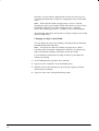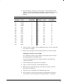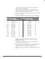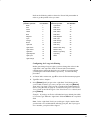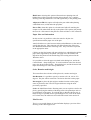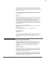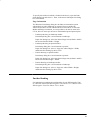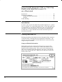
1
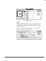
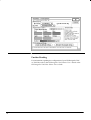
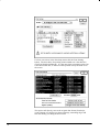
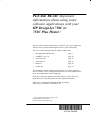
PLEASE READ: Important information about using some software applications with your HP DesignJet 750C or 750C Plus Plotter! This document contains information you need to set up your application software for use with the HP DesignJet 750C or 750C Plus Plotter. There is a section dealing with each of these applications: Intergraph MicroStation PC page 3 CADKEY 5.0 to 7.0 page 10 VersaCAD 386 page 15 AutoCAD LT page 24 MiniCad page 30 ArchiCAD page 33 The information in this document explains how to get help, locate the driver software, answer configuration questions, use some additional features, and troubleshoot while configuring. If you can’t find your application in the list above, refer to the user’s guide that came with your plotter for some helpful information. HP-GL/2 is a trademark of Hewlett-Packard Company. AutoCAD is a trademark of Autodesk, Inc. Copyright Hewlett-Packard Company 1995 HP Part Number C4705-90006 Printed in Europe, September 1995 Introduction This document describes the most efficient way to successfully configure your software application to use the HP DesignJet 750C or 750C Plus plotter (HP part numbers C3195A/C3196A and C4708A/C4709A). Although your software application documentation contains general information about configuring devices, you’ll find this information to be helpful because it pertains specifically to the HP DesignJet 750C or 750C Plus plotter. Read all instructions and perform each step in this document in sequence. You’ll learn how to: Configure your device to work with your computer and your application software, Answer questions asked by your application during device configuration, and Use your software application and the device to configure additional features (optional). Before You Begin Here’s what you should do before using the instructions in this document: Install your software application on your computer, and Set up the HP DesignJet 750C or 750C Plus plotter using the instructions in the User’s Guide that was packaged with the device. The guide instructs you on loading media and print cartridges, and connecting the plotter to your computer. If You Need Help If you have questions about the information or instructions presented in this document, contact your software application dealer for help. If you need further assistance with your plotter, contact the HP Customer Support Center: HP Customer Support Center (208) 323–2551 7 a.m.–6 p.m.* Mountain Standard Time * The center closes at 4:00 p.m. on Wednesdays You can also refer to the documents that came with your software application and the user’s manual that came with your plotter or printer for more information. Using the HP DesignJet 750C or 750C Plus Plotter with Intergraph MicroStation PC Introduction . . . . . . . . . . . . . . . . . . . . . . . . . . . . . . . . . . . . . . . . . . . Before You Begin . . . . . . . . . . . . . . . . . . . . . . . . . . . . . . . . . . . . . . Connecting the Device to Your Computer . . . . . . . . . . . . . . . . . . . Configuring MicroStation . . . . . . . . . . . . . . . . . . . . . . . . . . . . . . . . Activating the Configuration Utility . . . . . . . . . . . . . . . . . . . . . Selecting the Device . . . . . . . . . . . . . . . . . . . . . . . . . . . . . . . . . Customizing the Driver . . . . . . . . . . . . . . . . . . . . . . . . . . . . . . . Generating a Plot . . . . . . . . . . . . . . . . . . . . . . . . . . . . . . . . . . . . . . . Plotting to a File . . . . . . . . . . . . . . . . . . . . . . . . . . . . . . . . . . . . Sending the File to the Device (Bi-Tronics/Centronics) . . . . . Sending the File to the Device (RS-232-C) . . . . . . . . . . . . . . . Plot Options . . . . . . . . . . . . . . . . . . . . . . . . . . . . . . . . . . . . . . . . . . . Using the Device’s Rotate Feature . . . . . . . . . . . . . . . . . . . . . . Producing Long-Axis Plots . . . . . . . . . . . . . . . . . . . . . . . . . . . . Generating Multiple Copies of a Plot . . . . . . . . . . . . . . . . . . . . Stopping a Plot . . . . . . . . . . . . . . . . . . . . . . . . . . . . . . . . . . . . . Further Reading . . . . . . . . . . . . . . . . . . . . . . . . . . . . . . . . . . . . . . . . 3 3 4 4 4 4 5 6 6 7 7 8 8 9 9 9 9 Introduction This section describes how to connect your HP DesignJet 750C or 750C Plus plotter (HP part numbers C3195A/C3196A and C4708A/C4709A) to a PC running MicroStation PC software by Intergraph. Read all the instructions and perform each step in this section in the order given. You’ll learn how to: • • • Connect the device to your computer Set up the MicroStation PC software Generate a plot or print file and send it to the device. Before You Begin Here’s a list of things to do before proceeding with the instructions in this section: • • Install MicroStation PC on your computer, and Set up the HP DesignJet 750C or 750C Plus Plotter using the instructions in the HP DesignJet 750C Plotter User’s Guide or the HP DesignJet 750C Plus Plotter User’s Guide, except skip the part about connecting the device to your computer. Before connecting the plotter or printer, first read the section in this document entitled “Connecting the Device to Your Computer.” 3 You can refer to any of these documents for more information: • • • • MicroStation PC User’s Guide MicroStation PC Reference Guide HP DesignJet 750C Plotter User’s Guide HP DesignJet 750C Plus Plotter User’s Guide. Connecting the Device to Your Computer Microstation PC includes a utility called Plotfile that allows you to send images directly to your HP DesignJet 750C or 750C Plus plotter via the RS-232-C interface. Since serial communication tends to be quite slow however, we recommend that you connect your device to the Bi-Tronics/Centronics interface; at the time you want to plot or print, you can send your file to the device using the MS-DOS COPY command. Refer to the HP DesignJet 750C Plotter User’s Guide or the HP DesignJet 750C Plus Plotter User’s Guide for complete instructions on connecting your HP DesignJet 750C or 750C Plus plotter to your PC through the Bi-Tronics/Centronics (parallel) or RS-232-C (serial) interface. Configuring MicroStation Activating the Configuration Utility MicroStation PC has a configuration utility called USCONFIG. If you are installing MicroStation PC for the first time, this utility will be automatically run as part of the installation process. If your copy of MicroStation PC has already been installed on your PC, follow these steps: 1. Change to the directory that contains the MicroStation PC program files by typing the following command and pressing Return: CD \USTATION 2. Start the configuration utility by typing the following command and pressing Return: USCONFIG 3. Select “Plotters” from the configuration utility menu. The configuration utility will display a list of all devices that are supported by MicroStation PC. Selecting the Device 1. At the top of the screen, you must select either English measuring units (inches) or metric measuring units (millimeters). Use the arrow keys on your keyboard to highlight the section you want and press the Return key. 4 2. Using the arrow keys, scroll down to the entry labeled “Hewlett-Packard HPGL/2” and press Return. 3. When the configuration is complete, select the “Save and Exit” option. Customizing the Driver MicroStation PC is supplied with a sample plotter configuration file for each of its supported plotters. A plotter configuration file defines all the necessary information to create a plot file including resolution, line weight, density, and the number of pens. Each of these files can be edited, with any text editor on your PC, to match your specific plotting needs. If you are using English units, the driver for the HP DesignJet 750C or 750C Plus plotter is \USTATION\PLOTTING\PLTCFG\HPGL2.PLT For metric units, the driver is \USTATION\PLOTTING\PLTCFG\HPGL2M.PLT After editing the English unit file (hpgl2.plt), it should look like this: ; HP-GL/2 Plotter config file – For all HP-GL/2 plotters num_pens=8 ; required record change_pen=both ; either ”color” or ”weight” size=(9.66,8.1)/num=0/off=(0,0)/name=a size=(15.66,10.6)/num=0/off=(0,0)/name=b size=(20.66,16.6)/num=0/off=(0,0)/name=c size=(32.66,21.6)/num=0/off=(0,0)/name=d size=(42.66,33.6)/num=0/off=(0,0)/name=e resolution(IN)=(0.00098425197,0.00098425197) ; specifies both res and units stroke_tolerance=4.5 ; unitless num 0 < tol < 10 pattern_len(1)=1 ; set pattern length 1 pattern_len(2)=1 ; set pattern length 2 pattern_len(3)=1 ; set pattern length 3 pattern_len(4)=1 ; set pattern length 4 pattern_len(5)=1 ; set pattern length 5 pattern_len(6)=1 ; set pattern length 6 autocenter end_plot=eject rotate = cw ; clockwise rotation model=HPGL2 ; plotter model number border/pen=1/filename/time ; leave this out for no border communication=(handshake=0,port=1,baud=19200,par=none,data=8,stop=1) default_extension = ’000’ ; default extension for plotfiles The metric unit file (hpgl2m.plt) should look like this: ; HP-GL/2 Plotter config file – For all HP-GL/2 plotters num_pens=8 ; required record change_pen=both ; either ”color” or ”weight” size=(263,200)/num=0/off=(0,0)/name=a4 size=(386,287)/num=0/off=(0,0)/name=a3 5 size=(560,410)/num=0/off=(0,0)/name=a2 size=(831,560)/num=0/off=(0,0)/name=a1 size=(1179,807)/num=0/off=(0,0)/name=a0 resolution(MM)=(0.025,0.025) ; specifies both res and units stroke_tolerance=4.5 ; unitless num 0 < tol < 10 pattern_len(1)=1 ; set pattern length 1 pattern_len(2)=1 ; set pattern length 2 pattern_len(3)=1 ; set pattern length 3 pattern_len(4)=1 ; set pattern length 4 pattern_len(5)=1 ; set pattern length 5 pattern_len(6)=1 ; set pattern length 6 autocenter end_plot=eject rotate = cw ; clockwise rotation model=HPGL2 ; plotter model number border/pen=1/filename/time ; leave this out for no border communication=(handshake=0,port=1,baud=19200,par=none,data=8,stop=1) default_extension = ’000’ ; default extension for plotfiles Generating a Plot Sending your output to the device requires two steps: • Issuing a plot command from MicroStation PC. This creates a file on your computer’s hard disk drive (or a floppy disk drive if that is what you specify), and • Sending the plot file to the device either using the MS-DOS COPY command or the MicroStation PC Plotfile utility. The next subsection, “Plotting to a file,” must be performed regardless of the type of connection you are using (Bi-Tronics/Centronics or RS-232-C). The following two sections are specific to the type of connection you are using. Follow the instructions that apply to your installation. Plotting to a File 1. When you are ready to plot your drawing, select “Plot” from the “File” menu of the MicroStation Command Window. The “Preview Plot” dialog box will appear. 2. On the right side of the “Preview Plot” dialog box are the page and drawing settings. These settings are stored in the HPGL2.PLT and HPGL2m.PLT files. They include the page name, the dimensions of the printable area, and the units used to specify the printable area. If these settings are correct, skip to step 5. Otherwise, proceed with the next step. 3. To change the page settings, click on the “Set Page Size” button. This opens the “Page Size” dialog box. 4. Click and hold on the “Page Name” field. Each of the page names you specified in the HPGL2.PLT (or HPGL2m.PLT if you specified metric units) are available. Highlight the desired choice and release the mouse button. Then click on the “OK” button to return to the “Preview Plot” dialog box. 6 5. Click on the “Options” button. The “Options” dialog box appears. Here you can specify a 90 degree rotation of the plot. In addition, you can specify that a fence or border be drawn around the plot. 6. Click the “OK” button after specifying the plot options you want. This returns you to the “Preview Plot” dialog box. 7. When you are satisfied with the plot parameters, click on the “Plot” button to generate the plot file. MicroStation PC will prompt you for a name of the file offering the name of the drawing file with the extension “.000” (or whatever you specified as the default extension in the HPGL2.PLT or HPGL2m.PLT file) as the default. Note: Unless you specify otherwise, MicroStation PC will put the file in the \USTATION\PLOTTING\PLTFILES subdirectory. You may specify another directory by selecting another location at plot time (for example, A:MYPLOT.000) or by changing the Plotfile Directory using the USCONFIG utility. Sending the File to the Device (Bi-Tronics/Centronics) The DOS command to send your file to the HP DesignJet 750C or 750C Plus plotter is the COPY command with the /b (binary file) option. For example, if you created a file named MYPLOT.000 and had your device connected to your computer’s parallel port 2 (LPT2), here is the command you would use to send the file: copy /b c:\ustation\plotting\pltfiles\myplot.000 lpt2: Be sure the appropriate size sheet of paper is loaded in the device or else your output may be clipped. Sending the File to the Device (RS-232-C) If your device is connected to the computer’s serial (RS-232-C) connection, you should use the Plotfile utility to send your file to the device. The instructions for using the Plotfile utility are as follows: 1. Exit MicroStation. (Note: See chapter 4 of the MicroStation PC User’s Guide for information on running the Plotfile utility from within MicroStation PC.) 2. Use the following command to ensure you are in the correct subdirectory: CD \USTATION 3. Type the Plotfile command followed by any desired options. The syntax for the Plotfile command is as follows: PLOTFILE [option option...option] [plotfile [plotfile...plotfile]] The options for the Plotfile utility are as follows: 7 /PORT=n The serial port that the device is connected to. The n parameter is the number corresponding to the number of the COM port. For example, /PORT=2 directs the output to COM2. The default port is set in HPGL2.PLT or HPGL2m.PLT. /NOMODEM This option causes the modem control signals to be ignored and should only be used with XON/XOFF or ACK/NAK handshaking protocols (Handshake modes 1 and 2, respectively, in HPGL2.PLT or HPGL2m.PLT). /ACKNAK This option sets ACK/NAK handshake mode overriding the handshake mode set in HPGL2.PLT or HPGL2m.PLT. /DELETE Instructs Plotfile to delete the file after it has been plotted or printed. /DELAY=n This option causes the insertion of n delay units between the transmission of each character to the device. The value of n must be between 0 and 500. The recommended starting value is 50. The actual duration of each delay unit depends on the speed of the computer system running Plotfile. plotfile A list of file specifications (separated by spaces) to be sent to the device. Full path names and wildcard characters are permissible. If no plot files are specified, you will be prompted to enter the file names. For example, let’s say you want to send “myplot.000” and “yourplot.000” to the device using the Plotfile utility. Your HP DesignJet 750C or 750C Plus plotter is on COM2 and you want the files “myplot.000” and “yourplot.000” deleted after they are produced. The following command should be typed at the MS-DOS prompt: PLOTFILE /PORT=2 /DELETE MYPLOT.000 YOURPLOT.000 Note: The /PORT=2 option is only necessary if you did not specify port 2 in the HPGL2.PLT or HPGL2m.PLT file. Plot Options Using the Device’s Rotate Feature MicroStation PC automatically rotates your drawing to form the best fit possible on the page size you have loaded. If you set up the HPGL2.PLT file (or HPGL2m.PLT if you specified metric units) as shown in this document, then you should load the media in portrait orientation. You can override the rotation default in the Options dialog box at plot time as explained in “Generating a Plot” above. 8 Producing Long-Axis Plots Long-axis plotting and printing can be performed with MicroStation PC by creating another page size in the HPGL2.PLT or HPGL2m.PLT configuration file. (Since the maximum number of page size entries in these files is five, you may have to delete an existing page size entry to make room.) The maximum length of a plot or print that the HP DesignJet 750C or 750C Plus plotter can generate is 64 inches (1625 mm). If you’re using English units, add the following line to the HPGL2.PLT file: size=(64,33.6)/num=0/off=(0,0)/name=long_axis If you’re using metric units, add the following line to the HPGL2m.PLT file: size=(1625,807)/num=0/off=(0,0)/name=long_axis Long-axis plotting example: Suppose you want to create a plotfile for a drawing that’s 35 feet (10.67 meters) long. After adding the appropriate line to your configuration file as described above, choose “plot” from the Command Window “File” menu. Then click the “Set Page Size” button to bring up the “Set Page Size” dialog box. Press and hold the “Page Name” field and select “long_axis” from the list of choices. Select “Done” and then “Plot” to generate the file. Generating Multiple Copies of a Plot Multiple copies of the plot or print can be obtained by repeating the COPY command or PLOTFILE command for each additional copy desired. If you are using the Plotfile utility, be sure you do not use the /DELETE option. Stopping a Plot The MS-DOS COPY command can be interrupted by holding down the CTRL key and pressing “C.” The Plotfile utility is interrupted by pressing “Q.” In either case, the computer will immediately quit sending the file to the device. The device will continue plotting or printing, however, until the buffer is empty or the Cancel key is pressed on the device’s front panel. Further Reading For information regarding the configuration of your HP DesignJet 750C or 750C Plus refer to the HP DesignJet 750C Plotter User’s Guide or the HP DesignJet 750C Plus Plotter User’s Guide. 9 Using the HP DesignJet 750C or 750C Plus Plotter with CADKEY versions 5.0 to 7.0 Introduction . . . . . . . . . . . . . . . . . . . . . . . . . . . . . . . . . . . . . . . . . . . . Before You Begin . . . . . . . . . . . . . . . . . . . . . . . . . . . . . . . . . . . . . . . Connecting Your Plotter to a PC . . . . . . . . . . . . . . . . . . . . . . . . . . . . Configuring the Software . . . . . . . . . . . . . . . . . . . . . . . . . . . . . . . . . Using the CONFIG Utility to Create Plot Defaults . . . . . . . . . . . Changing Settings at Plot Time . . . . . . . . . . . . . . . . . . . . . . . . . . Specifying Merge Mode through the Software . . . . . . . . . . . . . . Generating a Plot in CADKEY 7.0 . . . . . . . . . . . . . . . . . . . . . . . . . . Generating a Plot in CADKEY 5.0 . . . . . . . . . . . . . . . . . . . . . . . . . . Stopping a Plot . . . . . . . . . . . . . . . . . . . . . . . . . . . . . . . . . . . . . . . . . Further Reading . . . . . . . . . . . . . . . . . . . . . . . . . . . . . . . . . . . . . . . . . 10 10 11 11 11 13 13 13 14 14 14 Introduction This section describes how to connect your HP DesignJet 750C or 750C Plus plotter (HP part number C3195A/C3196A or C4708A/C4709A) to a PC running CADKEY software. Read all the instructions and perform each step in this section in the order given. You’ll learn how to: Connect the device to your computer Set up the CADKEY software Generate a plot or print file and send it to the device. Before You Begin Here’s a list of things to do before proceeding with the instructions in this section: Install CADKEY on your computer, and Set up the HP DesignJet 750C or 750C Plus Plotter using the instructions in the HP DesignJet 750C Plotter User’s Guide or the HP DesignJet 750C Plus Plotter User’s Guide. You can refer to any of these documents for more information: 10 Getting Started with CADKEY 386 CADKEY Utilities and Customization Guide HP DesignJet 750C Plotter User’s Guide HP DesignJet 750C Plus Plotter User’s Guide. Connecting Your Plotter to a PC Connecting a plotter to a PC can be done either by attaching the peripheral directly to the serial or parallel port of the PC, or associating the port with the appropriate queue when you are using a network. The only requirements are: When you use the plotter’s serial port, set the values for parity and baud rate exactly the same as the PC’s serial port. Specify the port name (com1, com2,...). Configuring the Software This section describes how to configure your CADKEY software to use the HP DesignJet 750C or 750C Plus plotter. Using the CONFIG Utility to Create Plot Defaults The CONFIG utility allows you to identify the type of device you are using and the default settings you will use when plotting or printing. These settings can be changed at the time of plotting or printing as explained in the next subsection. To configure CADKEY for the HP DesignJet 750C or 750C Plus: 1. From the DOS prompt, change to the directory that contains your CADKEY software and type CONFIG. 2. From the main menu, select 3 – Set plotter options 3. Select 10 – HPGL/2 Plotter 4. Select 11 – Enter paper size 5. Answer the following prompts by entering the desired dimensions from the table on page 11–6 of the HP DesignJet 750C Plotter User’s Guide or the HP DesignJet 750C Plus Plotter User’s Guide. Choosing one of the standard paper sizes offered may cause problems for the device when you try to nest plots. Enter plot paper X size in inches => Enter plot paper Y size in inches => 6. Press the RETURN key to accept the default values for the next four prompts: Enter Enter Enter Enter X Y X Y min min max max clip clip clip clip limit limit limit limit in in in in millimeters millimeters millimeters millimeters => => => => 7. Enter zero (0) at the next two prompts: 11 Enter X offset for plot => Enter Y offset for plot => 8. You will be asked to enter a default pen width for all of the pens. Use the default of 0.3 millimeters or enter a default of your own: Enter plotter pen width in millimeters => 9. You will be prompted to enter a pen velocity and a curve tolerance factor. Press Return to accept the default values. Enter value in cm/sec => Enter curve tolerance factor => 10. Select the pen sorting option. We recommend 2) Sort pens in low to high order for the HP DesignJet 750C or 750C Plus plotter. 11. Answer yes to the next prompt in order to change the assignments of plot pens to CADKEY colors. Use the table below to enter the assignments. Note: CADKEY’s colors wil be used when the device’s pen source is set to “Use settings from software”. Refer to “Selecting the source of pen settings (tables or software)” later in this document for more information. Set this pen... 1 2 3 4 5 6 7 8 ...to this value Set this pen... 1 2 3 4 5 6 7 8 9 10 11 12 13 14 15 16 ...to this value 9 10 11 12 13 14 15 16 12. Select the destination port. If your device is connected to LPT1, then enter +1. If your device is connected to LPT2, then enter +2, etc. When you use a parallel connection, specify the right port (lpt1, lpt2, ...), and if you use a networked plotter, indicate which logical port the plotter is associated with (lpt2, lpt3, ...). When you use networked plotters, do not use the optional notation for specifying a connection port (+2, +3), as this can cause problems. Always use the official notation (lpt2, lpt3, ...) 13. Choose 9 – Exit and save changes. This completes the configuration process. 12 Changing Settings at Plot Time You may want to use settings other than the defaults that you set up in the CONFIG utility. These settings can be adjusted at plot or print time by selecting the CONTROL PLOT SETUP menu. See the appropriate procedure for your CADKEY version below. Specifying Merge Mode through the Software Merge mode can also be activated from the software by modifying the /CADKEY/PLOTCAP file. Be very careful when making modifications to this file as mistakes can cause unpredictable results. (In most cases you will be better off using the front panel method.) Edit the PLOTCAP file and find the section of the file under the header: HP2PL|HPGL/2 Plotter:\ Find the line in that section that starts with in= and add the MC1 command so that it looks as follows: in=\E%–1BBPINMC1LA1,4,2,4PS:\ See the CADKEY Utilities and Customization Guide for more information on PLOTCAP. Generating a Plot in CADKEY 7.0 Follow these steps to generate a drawing in CADKEY: 1. Choose CONTROL PLOT from the CADKEY menu. 2. Select what you want to plot or print from the list of choices in the menu. 3. Choose an option for entity masking from the list of choices. In most cases ALL is a good choice. 4. CADKEY will prompt you to press the RETURN key on your keyboard, and then a SETUP dialog box will appear. 5. If you do not want to use the default plot or print values that you set up in the CONFIG utility, use this menu to make your changes. For example: the scale factor will be set to Auto by default, if you want to change this factor click on the Key In button and enter your own value; rotation and location of your output on the media can be controlled by clicking on the Loc button and opening the Location dialog box. 6. If you want to change the way the pens are sorted or mapped, click on the Pen button to open the Pen Setup dialog box. 7. When you have made all the changes you want to make click on OK in the SETUP dialog box. 8. CADKEY will now ask you to position the output within the media limits represented by the rectangle you can move relative to your drawing. 13 9. CADKEY will prompt you to press the RETURN key on your keyboard to begin plotting or printing. Generating a Plot in CADKEY 5.0 Follow these steps to generate a drawing in CADKEY: 1. Choose CONTROL PLOT from the CADKEY menu. 2. If you do not want to use the default plot or print values that you set up in the CONFIG utility, select SETUP and make your changes. Then return to the PLOT menu and continue with the next step. 3. From the PLOT menu, select AUTO. 4. If you want to change scaling and rotation, select YES and type in the values you want to use. 5. Choose COLOR. 6. Choose the NORMAL plotting option. 7. Select what you want to plot or print from the list of choices in the menu. 8. Choose an option for entity masking from the list of choices. In most cases ALL is a good choice. 9. CADKEY will prompt you to press the RETURN key on your keyboard to begin plotting or printing. Stopping a Plot The PLOTFAST utility is interrupted by pressing “Q”. The computer immediately stops sending the plot file to the plotter. The plotter may continue plotting, however, until its buffer is empty or the Cancel button is pressed on the plotter’s front panel. Further Reading For information regarding the configuration of your HP DesignJet 750C or 750C Plus refer to the HP DesignJet 750C Plotter User’s Guide or the HP DesignJet 750C Plus Plotter User’s Guide. 14 Using the HP DesignJet 750C or 750C Plus Plotter with VersaCAD 386 version 6.0 Introduction . . . . . . . . . . . . . . . . . . . . . . . . . . . . . . . . . . . . . . . . . . . . Before You Begin . . . . . . . . . . . . . . . . . . . . . . . . . . . . . . . . . . . . . . . Selecting and Configuring the HP-GL/2 Driver . . . . . . . . . . . . . . . . Using Some Selected VersaCAD Features . . . . . . . . . . . . . . . . . . . . Changing VersaCAD’s Line Widths (pen source = software) . . Changing an Object’s Pen Width . . . . . . . . . . . . . . . . . . . . . Changing an Object’s Line Width . . . . . . . . . . . . . . . . . . . . Setting VersaCAD’s Pen Numbers for the Desired Color (pen source = software) . . . . . . . . . . . . . . . . . . . . . . . . . . . . Configuring for Long-Axis Plotting . . . . . . . . . . . . . . . . . . . . . . Changing VersaCAD’s Shading (pen source = software) . . . . . . Further Reading . . . . . . . . . . . . . . . . . . . . . . . . . . . . . . . . . . . . . . . . . 15 15 16 17 17 18 19 20 21 22 23 Introduction This section describes how to connect your HP DesignJet 750C or 750C Plus plotter (HP part numbers C3195A/C3196A and C4708A/C4709A) to a PC running VersaCAD software. Read all the instructions and perform each step in this section in the order given. You’ll learn how to: Connect the device to your computer Set up the VersaCAD software Generate a plot file and send it to the device. Before You Begin Here’s a list of things to do before proceeding with the instructions in this section: Install VersaCAD on your computer, and Set up the HP DesignJet 750C or 750C Plus Plotter using the instructions in the HP DesignJet 750C Plotter User’s Guide or the HP DesignJet 750C Plus Plotter User’s Guide. You can refer to any of these documents for more information: VersaCAD QuickStart: Getting started with VersaCAD before reading the manual VersaCAD 386 version 6.0, volumes 1 and 2 HP DesignJet 750C Plotter User’s Guide HP DesignJet 750C Plus Plotter User’s Guide. 15 Selecting and Configuring the HP-GL/2 Driver VersaCAD 386 (version 6.0 and later versions) has an internal HP-GL/2 driver which is automatically loaded—but not selected or configured—when you first installed VersaCAD. Before you can send your VersaCAD drawings to the HP DesignJet 750C or 750C Plus plotter, the HP-GL/2 plotter driver must be selected and configured. You can select and configure the driver by using the following step-by-step instructions to edit VersaCAD’s Environment program. The driver can be re-configured at any time. 1. At VersaCAD’s main menu, type E to select the Environment program. 2. Type O to display the “Output devices:” menu. 3. When the “Drafting device:” field is displayed, press [Spacebar] or [Backspace] until “HP-GL/2 Plotter (assigns pens to colors)” or “HP-GL/2 Plotter (assigns pens to widths)” is displayed. Recommended for HP DesignJet 750C or 750C Plus: If you select “HP-GL/2 Plotter (assigns pens to colors),” changing an object’s pen number changes its color value, in VersaCAD. If you plot using VersaCAD’s pen palette (pen source = from software), all objects will have the assigned color. Refer to “Changing VersaCAD’s colors (pen source = software)” on page 22 and the section on “Changing pen widths and colors” in the HP DesignJet User’s Guide for more information. If you select “HP-GL/2 Plotter (assigns pens to widths),” changing an object’s pen number changes its line width value in VersaCAD. If you make this selection and you plot using VersaCAD’s pen palette (pen source = from software), all objects will be solid black. Refer to “VersaCAD’s line widths (pen source = software)” on page 17 and the section on “Changing pen widths and colors” in the HP DesignJet User’s Guide for more information. When you’ve made your decision, display the appropriate selection and press [Return] to select it. 4. At the “port:” field, type the name of the port that connects the device and your computer, type a colon (:), then press [Return]. Example: Type LPT1: [Return] if your port is called “LPT1.” Note: Be sure to type the colon, or you won’t be able to plot or print. 5. At the “use hardware features:” field, press [Spacebar] until “Yes” is displayed, then press [Return]. 6. At the “right limit:” field, refer to the table on page 11–6 of the HP DesignJet 750C Plotter User’s Guide or the HP DesignJet 750C Plus Plotter User’s Guide and type the x-axis width (in inches) that corresponds to the media size you’re using. Then press [Return]. Note: If you want to produce a long-axis plot, you need to type the x-axis length you want your plot to be instead of the value shown in the table. See “Configuring for Long-Axis Plotting” on page 21. 16 7. At the “top limit:” field, refer to the table on page 11–6 of the HP DesignJet 750C Plotter User’s Guide or the HP DesignJet 750C Plus Plotter User’s Guide and type the y-axis height (in inches) that corresponds to the media size you’re using. Then press [Return]. 8. At the “Plot Utility device:” field, press [Return] to select “Same as above.” 9. At the “spoolfiles:” field, either press [Return] to select the displayed pathname (“Old Pathname:”) where spool files will be saved (when you plot to a file), or type a new pathname and press [Return]. 10. Press X to exit the Environment program. When prompted, press any key to return to VersaCAD’s main menu. This concludes the required driver selection and configuration process. Continue reading to learn how to use some powerful features of VersaCAD and the HP DesignJet 750C or 750C Plus plotter. Using Some Selected VersaCAD Features This section contains instructions on how to use the following VersaCAD features: Changing VersaCAD’s line widths (pen source*= from software) Setting VersaCAD’s pen numbers to achieve the desired plotted color (pen source* = software) Configuring for long-axis plotting Changing VersaCAD’s shading (pen source*= from software) * The source of pen settings can be either from your software (default) or from the device. See the HP DesignJet 750C Plotter User’s Guide or the HP DesignJet 750C Plus Plotter User’s Guide for information on setting from the front panel. Changing VersaCAD’s Line Widths (pen source = software) When plotting with VersaCAD’s pen parameters, the plotted line widths are calculated from this formula: plotted line width = object’s pen width + object’s line width The default object pen width is .35 mm (.0138 inches), and the default object line width is 0 mm. If you selected “HP-GL/2 Plotter (assigns pens to colors)” in the Environment configuration, the object’s pen width is fixed at .350 mm (.0138 inches), changing the above formula to the following: plotted line width = .350 mm + object’s line width 17 Therefore, if you made this configuration selection, the only way you can change the plotted line width is by changing the object’s line width value. Note: With “HP-GL/2 Plotter (assigns pens to colors)” selected, changing the object’s pen width in VersaCAD will have no affect on the plotted line width, but it will affect shading (refer to “Changing VersaCAD’s shading (pen source = software)” later in this document). The following subsections describe how to change an object’s pen width and line width values. Changing an Object’s Pen Width You can change an object’s pen width by selecting the object and using the Modify/Properties/Pen menu. Note: You must have “HP-GL/2 Plotter (assigns pens to widths)” selected in the Environment configuration; otherwise, the changes you make will affect the shading of the object, not the pen width. Use the following instructions to change an object’s pen width from within your drawing. 1. At the Drafting menu, type M to select “Modify.” 2. Type P to select “Properties” from the Modify menu. 3. With the cursor in the drawing area, press the [<] or [>] keys until the desired object is blinking. 4. Type P to select “Pen” from the Mod Props menu. 18 5. In the “proposed:” field, type a value from the “VersaCAD Object Pen Number” column of the following table that corresponds to the value you want from the “VersaCAD Object Pen Width” column. Then press [Return]. VersaCAD Object Pen Width millimeters inches VersaCAD Object Pen Number millimeters inches VersaCAD Object Pen Number .350 (default) .0138 (default) 1 2.75 .108 17 .125 .00492 2 3.00 .118 18 .187 .00736 3 3.25 .128 19 .250 .00984 4 3.50 .138 20 .312 .0123 5 3.75 .148 21 .375 .0148 6 4.00 .157 22 .500 .0197 7 4.25 .167 23 .625 .0246 8 4.50 .177 24 .687 .0270 9 4.75 .187 25 .800 .0315 10 5.00 .197 26 1.00 .0394 11 5.25 .207 27 1.25 .0492 12 5.50 .216 28 1.50 .0591 13 5.75 .226 29 1.75 .0689 14 6.00 .236 30 2.00 .0787 15 6.25 .246 31 2.50 .0984 16 6.50 .256 32 6. Type U to select “Update” from the Mod Props menu. The screen should now reflect your change. 7. Repeat steps 3 through 6 for the remaining objects you want to change. Changing an Object’s Line Width You can change an object’s line width by selecting the object and using the Modify/Properties/lineWidth menu. Use the following instructions to change an object’s line width from within your drawing. 1. At the Drafting menu, type M to select “Modify.” 2. Type P to select “Properties” from the Modify menu. 3. With the cursor in the drawing area, press the [<] or [>] keys until the desired object is blinking. 4. Type W to select “lineWidth” from the Mod Props menu. 5. In the “proposed:” field, refer to the table of defaults below and type a value from the “VersaCAD Object Line Width Number” column that 19 corresponds to the value you want from the “VersaCAD Object Line Width” column. Then press [Return]. Note: Notice that the default increment size in the table is 1/64 or .0156 inches (.397 mm). You can change the increment size using the Output/Units/lineWidth menu (“increment:” field). 6. Type U to select “Update” from the Mod Props menu. The screen should now reflect your change. 7. Repeat steps 3 through 6 for the remaining objects you want to change. VersaCAD Object Line Width (Defaults) VersaCAD Object Line Width Number millimeters inches VersaCAD Object Line Width Number millimeters inches 0 0 1 6.35 16/64 (.250) 17 .397 1/64 (.0156) 2 6.75 17/64 (.266) 18 .794 2/64 (.0312) 3 7.14 18/64 (.281) 19 1.19 3/64 (.0469) 4 7.54 19/64 (.297) 20 1.59 4/64 (.0625) 5 7.94 20/64 (.312) 21 1.98 5/64 (.0781) 6 8.33 21/64 (.328) 22 2.38 6/64 (.0938) 7 8.73 22/64 (.344) 23 2.78 7/64 (.109) 8 9.13 23/64 (.359) 24 3.17 8/64 (.125) 9 9.53 24/64 (.375) 25 3.57 9/64 (.141) 10 9.92 25/64 (.391) 26 3.97 10/64 (.156) 11 10.3 26/64 (.406) 27 4.37 11/64 (.172) 12 10.7 27/64 (.422) 28 4.76 12/64 (.187) 13 11.1 28/64 (.437) 29 5.16 13/64 (.203) 14 11.5 29/64 (.453) 30 5.56 14/64 (.219) 15 11.9 30/64 (.469) 31 5.95 15/64 (.234) 16 Setting VersaCAD’s Pen Numbers for the Desired Color (pen source = software) VersaCAD’s pens (and their associated colors) will be used in your output if you have done the following: 1. If you chose “HPGL/2 Plotter (assigns pens to colors)” in step 3 of the configuration process you completed earlier (see “Selecting and configuring the HP-GL/2 plotter driver” on page 16), and 2. If the pen settings source is “from software” (default setting) in the front panel. 20 Refer to the following table to choose the VersaCAD pen number in order to get the printed colors you want. If you want this color plotted or printed ... ...choose this Pen Number... If you want this color plotted or printed ... ...choose this Pen Number... Black 1 Light Brown 17 Red 2 Dark Red 18 Green 3 Dark Green 19 Yellow 4 Dark Yellow 20 Blue 5 Dark Blue 21 Magenta 6 Dark Magenta 22 Cyan 7 Dark Cyan 23 Orange 8 Dark Orange 24 Brown 9 Dark Brown 25 Light Red 10 Dark Gray 26 Light Green 11 Medium Dark Gray 27 Light Yellow 12 Medium Gray 28 Light Blue 13 Medium Light Gray 29 Light Magenta 14 Light Gray 30 Light Cyan 15 White 31 Light Orange 16 Configuring for Long-Axis Plotting Before generating a long-axis plot, you must change the values in the “right limit” and “top limit” fields of VersaCAD’s Environment configuration to reflect the desired x-axis width of your plot and the y-axis height of the loaded media, respectively. Use the following procedure: 1. At VersaCAD’s main menu, type E to select the Environment program. 2. Type O to select “Output.” 3. Press [Return] until you get to the “right limit” field, then type the x-axis width (in inches) you want your plot to be and press [Return]. Then in the “top limit” field, type the y-height of the loaded media (in inches, using the table on page 11–6 of the HP DesignJet 750C Plotter User’s Guide or the HP DesignJet 750C Plus Plotter User’s Guide) and press [Return]. Example: If you have an E-size roll loaded and your desired plot width is 75 inches, type 75 in the “right limit” field and 35.6 in the “top limit” field. Note: In the “right limit” field, you could type a higher number than your desired x-axis width without affecting your plot, but if you type a lower number, your plot will be clipped. 21 4. Press [Return] several times until the prompt at the bottom of the page says “[N] Next menu [X] eXit [esc] Aborts all changes.” Press X, then [Return] to return to the main menu. Changing VersaCAD’s Shading (pen source = software) The default shading is 100% black for all objects. If you want grayscale, you can change an object’s shading by selecting the object and using the Modify/Properties/Pen menu. Note: You must have “HP-GL/2 Plotter (assigns pens to colors)” selected in the Environment configuration; if you have “(assigns pens to widths)” selected instead, changing the object’s pen width will affect the plotted line width. Use these instructions to change an object’s shading from within a drawing. 1. At the Drafting menu, type M to select “Modify.” 2. Type P to select “Properties” from the modify menu. 3. Press the [<] or [>] keys until the desired object is blinking. 4. Type P to select “Pen” from the Mod Props menu. 5. In the “proposed:” field, refer to the following table and type the Pen Number that corresponds to the % shading you want for that object. Then press [Return]. There are 21 possible shading values. If you want this shade (%) of black ... ...type this Pen If you want this shade Number ... (%) of black ... ...type this Pen Number ... 0% (white) 31 55% 24 5% 12 60% 6, 23, or 27 10% 4 65% 17 15% 15 70% 2 or 19 20% 30 75% 9 or 22 25% 11 80% 18 or 26 30% 7, 14, or 16 85% 25 35% 10 or 20 90% 5 40% 3 or 8 95% 21 45% 13 or 29 100% (black) 1 50% 28 6. Type U to select “Update” from the Mod Props menu. The screen should now reflect your change. 7. Repeat steps 3 through 6 for the remaining objects you want to change. 22 Further Reading For information regarding the configuration of your HP DesignJet 750C or 750C Plus refer to the HP DesignJet 750C Plotter User’s Guide or the HP DesignJet 750C Plus Plotter User’s Guide. 23 Using the HP DesignJet 750C or 750C Plus Plotter with AutoCAD LT Introduction . . . . . . . . . . . . . . . . . . . . . . . . . . . . . . . . . . . . . . . . . . . . Before You Begin . . . . . . . . . . . . . . . . . . . . . . . . . . . . . . . . . . . . . . . Plotting from AutoCAD LT . . . . . . . . . . . . . . . . . . . . . . . . . . . . . . . Setup and Default Information . . . . . . . . . . . . . . . . . . . . . . . . . . Pen Parameters . . . . . . . . . . . . . . . . . . . . . . . . . . . . . . . . . . . . . . Additional Parameters . . . . . . . . . . . . . . . . . . . . . . . . . . . . . . . . Paper Size and Orientation . . . . . . . . . . . . . . . . . . . . . . . . . . . . . Scale, Rotation and Origin . . . . . . . . . . . . . . . . . . . . . . . . . . . . . Plot Preview. . . . . . . . . . . . . . . . . . . . . . . . . . . . . . . . . . . . . . . . . Plotting . . . . . . . . . . . . . . . . . . . . . . . . . . . . . . . . . . . . . . . . . . . . Hints on Using AutoCAD LT . . . . . . . . . . . . . . . . . . . . . . . . . . . . . . Page Size Selection . . . . . . . . . . . . . . . . . . . . . . . . . . . . . . . . . . . Page Orientation . . . . . . . . . . . . . . . . . . . . . . . . . . . . . . . . . . . . . Further Reading . . . . . . . . . . . . . . . . . . . . . . . . . . . . . . . . . . . . . . . . . 24 24 25 25 26 26 27 27 27 28 28 28 29 29 Introduction In order to plot or print from AutoCAD LT a Windows driver is required. For your HP DesignJet 750C or 750C Plus plotter, the recommended one is the HP developed driver, that was packaged with your device, see the section below. Before You Begin Here’s what you should do before reading this section: D Install the driver software on the disk labelled: HP Printer Driver (HP-GL/2 and HP RTL) for MicrosoftR Windows 3.1 (v 2.0) that was packaged with the device, and D Set up the HP DesignJet 750C or 750C Plus plotter using the instructions in the user’s guide that was packaged with the device. The guide instructs you on loading media and print cartridges, and connecting the device to your computer. You should also read the guide AutoCAD Drivers for HP Plotters, where more detailed information is given. 24 Plotting from AutoCAD LT Plotting from AutoCAD LT is done through the PLOT command, where many configuration options are included. AutoCAD LT stores all the current plot specifications in the configuration file ACLT.CFG so that it is not necessary to re-enter the same parameters every time the Plot command is issued. The plot procedure in AutoCAD LT is very easy because there is no need to select specific devices. There is only one default device which is the System Printer. By default, AutoCAD LT, uses dithered output to allow the device to simulate more colors than it actually supports by creating combinations from the pure color palette. The dithered output can be disabled for those devices that do not support it, like pen plotters, simply by changing the DITHER setting to 0. This is done from the AutoCAD command line by typing: DITHER 0. The Plot command performs the following tasks: – – – – – – – – – Sets the Pen Assignments, such as pen number, pen width and linetype, all of them associated with each color that appears on the screen. Selects the printing area with the variables: Display, Limits, View or Window area. Removes hidden lines. Selects the units and specifies the paper size in inches or in millimetres. Specifies the orientation of the paper. Sets the scale, rotation and origin parameters. Obtains a full or partial preview of the drawing. Saves all the plot settings to a file with the .PCP extension for future use. Plot the drawing to a file or directly to the plotter. The plot dialog box can be accessed by: typing PLOT at the command line, clicking on the “Plot” button of the Toolbar, or selecting from the “File” menu the option “Print/Plot”. Setup and Default Information This area is used to save the setup information to a plotting configuration file and specify the print setup parameters. Clicking the “Print/Plot Setup & Default Selection” button will open its dialog box. – File Defaults: Save Defaults to File: this option will save all the basic plot specifications and pen assignments in a file with the .PCP extension. The PCP files can be edited with an ASCII editor like the Windows Notepad. This provides an easy way of modifying the settings of the pen assignments. 25 Get Defaults from File: loads all the plot specifications from an existing PCP file. It is a useful way of saving all the plotting parameters together with the drawing. – Device Specific Configuration: Show Device Requirements: displays additional configuration information about the current plotter driver. Print/Plot Setup: this option will access the driver configuration. Because the System Printer is being used it will display the Print Setup dialog box. Pen Parameters This area of the PLOT command controls the pen settings. Each entity of the drawing is assigned a color. These colors can be assigned either to a specific layer or to an individual object. When plotting or printing, all entities with the same color are drawn using the same pen parameters (pen number, linetype and pen width). Therefore the user must assign pen parameters to the colors currently used in the drawing. It is possible to work with 255 different colors. The width will be expressed in inches or millimetres depending on the setting of the Paper Size and Orientation option. Clicking the Pen Assignments button and then the Feature Legend button will display a window with the possible linetypes which can be used in the drawing by assigning them to a pen number. Additional Parameters In this section of the PLOT main dialog box it is possible to select a rectangular area of the drawing to be plotted – Display, Extents, Limits, View or Window – or to select parameters such as Hide Lines or Adjust Area Fill. Display: plots the view in the current viewport, be it model space or paper space. Extents: the plot will consist of the portion of the drawing that currently contains entities, similar to the ZOOM Extents command. These extents are updated automatically as new entities are drawn, but reductions in the extents (as produced with Erase, Move or Scale) are recognized only when a Zoom All or Zoom Extents are performed. So, if the drawing has been edited, it is safer to perform a Zoom Extents before using this option. Limits: plots the entire drawing area as defined by the drawing limits. View: plots a view that has been previously saved using the View command. To select a view, click on the View button and AutoCAD will display all the views currently saved for the current drawing. Window: plots any portion of the drawing by specifying the lower-left corner and the upper-right corner of the area to be plotted. To specify a window click on the Window button. 26 Hide Lines: selecting this option will mean that at plotting time, all hidden lines will be removed from the objects drawn. For a complex drawing removing hidden lines can add significantly to the plotting time. Adjust Area Fill: this option will adjust the pen width when plotting solid-filled traces, solids and wide polylines. Plot to File: when this option is selected AutoCAD will send the plot output to a file rather than directly to the plotter. This option will prompt the user for a file name for the plot file, which will have a PLT extension. Paper Size and Orientation In this section it is possible to select the units for all plot size specifications and the paper size of the plot. AutoCAD allows to select between inches and millimetres as the units to specify the plot size. This selection will affect: Paper Size, Plot Area, Pen Width and Plotted units=Drawing units. They will all be expressed in the appropriate units. Clicking on the Size button will open a dialog box which displays all the paper sizes supported by the plotter. The page sizes shown here will depend on the plotter model and the Page Size setting selected in the Windows driver. It is possible to select the paper size both in this dialog box, and in the Control Panel – Setup dialog box. To avoid confusion select the desired paper size in the Control Panel – Setup dialog box, and in the AutoCAD Paper Size dialog box select always MAX size. Scale, Rotation and Origin This area allows the selection of the plot scale, rotation and origin. Plot Rotation: it is posible to specify a rotation of 0, 90, 180 or 270 degrees. The plot will be rotated in a clockwise direction on the paper. Plot Origin: to place the plot origin at another location on the paper, enter its position in the X and Y Origin edit boxes using the units previously specified. Scale: the label Plotted units=Drawing units, sets an explicit scale for the plot by specifying the number of drawing units to be plotted per inch or per millimetre on the paper. To scale the plot so that the chosen view is made as large as possible for the specified paper size, click on the Scale to Fit check box; the edit boxes will reflect the actual scale used to fit. Plot Preview This is a very useful feature of AutoCAD that displays a preview of the drawing on the chosen paper size. 27 Partial: shows graphically the effective plot area on the paper size and how correctly the plot will fit. AutoCAD will consider the area selected (Display, Extents, Limits, View or Window), the paper size, the scale, the plot origin and the rotation. Full: a full preview displays the drawing on the screen as it will appear on the paper. It is possible to perform a Dynamic Pan or a Zoom of an area in the drawing. Plotting When sending the drawing to a device, AutoCAD LT scans the drawing from top to bottom processing horizontal strips to be plotted. For many devices, AutoCAD LT can truncate trailing blank spaces from the right end of each horizontal strip, saving time by not processing this information. Thus, a drawing without border lines can often be processed more quickly than the same drawing with border lines. When finally clicking on the OK button to plot the drawing, AutoCAD will display the following messages: Effective plotting area: width by height where width and height are expressed in the current size units (inches or millimeters). Position paper in plotter Press RETURN to continue or S to stop for hardware setup. Regeneration done: nn% Vector sort done: nn% Plot complete. After a Full Preview, the ”Regeneration done” message is not displayed because it has already been done to provide a Full Preview. The vector sort is done depending on the contents of the drawing and the device selected. Hints on Using AutoCAD LT Many of the problems existing in the AutoCAD for Windows version with the System Printer driver have been fixed in AutoCAD LT. For example, the combination of line widths and linetypes is plotted correctly and the “Plot to File” option works fine. Still the “Page Size” and “Orientation” can be selected in two different places which can be confusing. Page Size Selection The page size selection can be confusing because there are two dialog boxes where it is possible to set a page size. One of them is the Paper Size dialog box of the PLOT command and the other is the Print Setup dialog box of the Control Panel window. To access AutoCAD Paper Size dialog box, load the PLOT command in AutoCAD and click on the Size button. To access the Window’s Print Setup dialog box, click on the Control Panel icon, then click on Printers, select the printer and press the Setup button. 28 To specify the media size which is loaded in the device, open the Print Setup dialog box and select it. Then, in the AutoCAD Paper Size dialog box, select MAX Page Orientation The Windows Print Setup dialog box includes an Orientation option which allows to select landscape or portrait. However unlike the AutoCAD for DOS version with the HP driver that allows to select the Media and Image orientation, it is not possible to do this in AutoCAD LT. So, here are some tips on how to obtain landscape and portrait plots. – Landscape drawing on landscape media: Print Setup dialog box: set Orientation to landscape. – Paper Size dialog box: select the desired Page Size (default is MAX) but be sure that the Width > Height. Landscape drawing on portrait media: Print Setup dialog box: set Orientation to portrait. – Paper Size dialog box: select a Page Size where Height > Width, and Rotate the drawing by 90° or 270°. Portrait drawing on portrait media: Print Setup dialog box: set Orientation to portrait. – Paper Size dialog box: select the desired Page Size (default is MAX) but be sure that the Height > Width. Portrait drawing on landscape media: Print Setup dialog box: set Orientation to landscape. Paper Size dialog box: select a Page Size where Width > Height, and Rotate the drawing by 90° or 270°. Further Reading For information regarding the configuration of your HP DesignJet 750C or 750C Plus refer to the HP DesignJet 750C Plotter User’s Guide or the HP DesignJet 750C Plus Plotter User’s Guide. 29 Using the HP DesignJet 750C or 750C Plus Plotter with MiniCad version 5.0 on a Macintosh Introduction . . . . . . . . . . . . . . . . . . . . . . . . . . . . . . . . . . . . . . . . . . . . Plotting from MiniCad . . . . . . . . . . . . . . . . . . . . . . . . . . . . . . . . . . . Setup and Default Information . . . . . . . . . . . . . . . . . . . . . . . . . . Plotting . . . . . . . . . . . . . . . . . . . . . . . . . . . . . . . . . . . . . . . . . . . . Further Reading . . . . . . . . . . . . . . . . . . . . . . . . . . . . . . . . . . . . . . . . . 30 30 30 31 32 Introduction In order to plot or print from MiniCad by Diehl Graphsoft, Inc., a plotter driver is required. For your HP DesignJet 750C or 750C Plus plotter, the recommended one is the HP developed driver, that was packaged with your device, see the section below. You can also use a commercially available driver, such as MacPlot Professional from MicroSpot and PowerPlot from GDT. Plotting from MiniCad Plotting and printing from MiniCad is done through the Print command on the File menu, or through the Print command of a Worksheet. You can also save objects and data created in MiniCad in various formats by using the Export command. Setup and Default Information MiniCAD uses the driver selected at Chooser level, so most of the selectable options are the common ones. MiniCAD includes its own High Resolution Printing option. When you use the PostScript driver that comes included with the HP DesignJet 750C/PS or 750C Plus/PS plotter, select 300 dots per inch. When you use other driver, select the nearest value to this. 30 Plotting When you print through the PostScript driver, all text, dimensions (their values) and notes, are printed with a clear, but perceptible, background formed of dots. Try using a font with a pure white background wirebox to overcome this defect. If you use a third-party driver (for example, an HP-GL/2 driver such as MacPlot), everything will be printed properly. 31 Further Reading For information regarding the configuration of your HP DesignJet 750C or 750C Plus refer to the HP DesignJet 750C Plotter User’s Guide or the HP DesignJet 750C Plus Plotter User’s Guide. 32 Using the HP DesignJet 750C or 750C Plotter with ArchiCAD version 4.5 on a Macintosh Introduction . . . . . . . . . . . . . . . . . . . . . . . . . . . . . . . . . . . . . . . . . . . . Plotting from ArchiCAD . . . . . . . . . . . . . . . . . . . . . . . . . . . . . . . . . Setup and Default Information . . . . . . . . . . . . . . . . . . . . . . . . . . Further Reading . . . . . . . . . . . . . . . . . . . . . . . . . . . . . . . . . . . . . . . . . 33 33 33 36 Introduction In order to plot or print from ArchiCAD from Graphisoft, a plotter driver is required. For your HP DesignJet 750C or 750C Plus plotter, use the HP-GL/2 driver provided with the application. Plotting from ArchiCAD Plotting from ArchiCAD is done through the PlotMaker application program. Setup and Default Information There are several options for printing using the HP DesignJet 750C or 750C Plus. If the plotter has the PostScript option installed, this is one of them. Otherwise, the application itself includes an HP-GL/2 driver that can handle this plotter. The Plot Setup... command in ArchiCAD lets you specify information about the device. In the File menu, select the Plot Setup option and a window menu appears. From the model option, select the DesignJet Family (HP DesignJet 200/220/600/650C), and then select the paper size and orientation. The connection will be made through the serial printer port of the Macintosh. All the parameters of this port must be set corresponding to those of the plotter’s serial port (baud rate and parity). 33 For font conversion, in the Plot Setup menu click the Font Plotting button. The best choice for printing with included text is the third one (TrueType/PostScript/Bitmap). It is the most time-consuming option, but is the most usable one, as the text will be printed exactly the same as on the screen. This option will directly convert the original font format (PostScript, vector, bitmap or TrueType) to plotter language, smoothing edges and fills and thereby providing the best results. 34 For printing, select the Plot option in the File menu, specifying the different options available for printing (destination, number of copies, and so on). Pay special attention to the option that applies to Text & Markers, as different settings will produce different results. Refer to the ArchiCAD 4.5 Reference Manual for more information; as general rule we recommend selecting the “Resize to Plotting Scale” option. This will maintain the appearance of the included text relative to the rest of the drawing. When you print through the PostScript driver, this window changes slightly. Note that, based on the ratio of the Printing Scale to the selected Page Size (as in the Page Setup submenu), tiling (the generation of several sheets to contain the picture) is automatically arranged for plotting the whole drawing. 35 Further Reading For information regarding the configuration of your HP DesignJet 750C or 750C Plus refer to the HP DesignJet 750C Plotter User’s Guide or the HP DesignJet 750C Plus Plotter User’s Guide. 36 Notes Notes Notes Driver Distribution We are continually striving to improve our drivers. As we update these drivers, they are made available through our driver distribution channel. In the U.S.A., call 1-303-339-7009. In Europe, contact Bridge/KOP. In other regions of the world, contact your local dealer or HP sales and support office. Windowsr is a registered trademark of Microsoft Corporation. PostScriptr is a registered trademark of Adobe Systems Incorporated Macintoshr is a registered trademark of Apple Computer Incorporated PANTONEr* Colors generated by the HP DesignJet 750C and 750C Plus are four-color process simulations and may not match PANTONE-identified solid color standards. Use current PANTONE Color Reference Manuals for accurate color. PANTONE color simulations are only obtainable with this product when driven by qualified Pantone-licensed software packages. Contact Pantone, Inc. for a current list of qualified licensees. *Pantone, Inc.’s check-standard trademark for color. ePantone, Inc., 1988. R E Copyright Hewlett-Packard Company 1995, 1996 Printed on recycled paper All rights reserved. No part of this document may be photocopied, reproduced, or translated to another language without the prior written consent of Hewlett-Packard Company. Hewlett-Packard Company Barcelona Division Avda. Graells, 501 08190 Sant Cugat del Vallès Barcelona, Spain