1
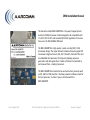
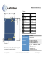
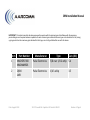
RM1-‐900MRTR OEM InstallaSon Manual Technical Support: Phone: +1-‐604-‐379-‐5091 Email: [email protected] Date: August 2013 112-‐17 Fawce4 Rd. Coquitlam BC Canada V3K 6V2 Revision: 4 Page 1 OEM Installa1on Manual The Aarcomm model RM1-‐900MRTR is a frequency hopped spread spectrum (FHSS) transceiver module designed to be compaSble with U.S. (FCC Part 15.247) and Canadian (RSS-‐210) regulaSons for license free use in the 902-‐928MHz ISM band. The RM1-‐900MRTR is a high-‐quality, system-‐on-‐chip (SOC), FHSS transceiver design. The major elements include a frequency agile SOC transceiver integrated circuit, LNA, PA, T/R switch, harmonic filter and an embedded microprocessor for frequency hopping sequence generaSon and data generaSon. Packets of data are transmi4ed to, and received from, a maSng transceiver. The RM1-‐900MRTR is intended to be used with a host processor with an SPI, UART or USB interface. We have provided a soeware stack for the host processor, to make it easy to interface with the RM1-‐900MRTR. Date: August 2013 112-‐17 Fawce4 Rd. Coquitlam BC Canada V3K 6V2 Revision: 4 Page 2 OEM Installa1on Manual Pinout 1 USB_P 3 GND 5 SPI_SOMI 7 SPI_SIMO 9 SPI_TE 11 +4V output 13 TX2 15 Vin 17 RX2 19 GND 21 GND 23 GPIO2 25 GND 2 USB_N 4 VBUS 6 SPI_CLK 8 TX 10 RX 12 +4V output 14 Vrtc 16 Vin 18 GPIO1 20 Link 22 RSSI 24 DAC/GPIO3 26 nPOR Vin range +7 to +40 VDC Power requirements 24 VDC @ 250mA RF connector RM1-‐900MRTR-‐S: straight MCX RM1-‐900MRTR-‐L: right angle MCX RM1-‐900MRTR-‐R: right angle MCX Host connector 0.05” x 0.05” pitch, female, 2x13, 26 posiSon, Height: RM1-‐900MRTR-‐S: 0.45” RM1-‐900MRTR-‐L: 0.16” RM1-‐900MRTR-‐R: right angle This informaSon should be referenced when designing the host interface PCB to the RM1-‐900MRTR Date: August 2013 112-‐17 Fawce4 Rd. Coquitlam BC Canada V3K 6V2 Revision: 4 Page 3 OEM Installa1on Manual United States (FCC) This equipment complies with Part 15 of the FCC rules and regulaSons. To fulfill FCC CerSficaSon requirements, an OEM manufacturer must comply with the following regulaSons: 1. The modular transmi4er must be labelled with its own FCC ID number, and, if the FCC ID is not visible when the module is installed inside another device, then the outside of the device into which the module is installed must also display a label referring to the enclosed module. 2. The module may only be used with antennas that have been tested and approved for use. Example of label required for OEM product containing RM1-‐900MRTR module: Contains FCC ID: 2AAXW900MRM1 The enclosed device complies with Part 15 of the FCC Rules. OperaSon is subject to the following two condiSons: (i.) this device may not cause harmful interference and (ii.) this device must accept any interference received, including interference that may cause undesired operaSon. WARNING: The Original Equipment Manufacturer (OEM) must ensure that the OEM modular transmi4er must be labeled with its own FCC ID number. This includes a clearly visible label on the outside of the final product enclosure that displays the contents shown below. If the FCC ID is not visible when the equipment is installed inside another device, then the outside of the device into which the equipment is installed must also display a label referring to the enclosed equipment. IMPORTANT: This equipment complies with Part 15 of the FCC Rules. OperaSon is subject to the following two condiSons: (1) this device may not cause harmful interference, and (2) this device must accept any interference received, including interference that may cause undesired operaSon (FCC 15.19). IMPORTANT: The RM1-‐900MRTR Module has been cerSfied by the FCC for use with other products without any further cerSficaSon (as per FCC secSon 2.1091). ModificaSons not expressly approved by Aarcomm Systems Inc. could void the user's authority to operate the equipment. OEM INSTRUCTIONS: The RM1-‐900MRTR Module is limited to OEM installaSons only. OEM integrators must ensure that the end-‐user has no manual instrucSons to remove or install the module. OEM’s must comply with FCC marking regulaSon part 15 declaraSon of conformity (SecSon 2.925(e)). This module is to be installed only in mobile or fixed applicaSons (Please refer to FCC CFR 47 Part 2.1091(b) for a definiSon of mobile and fixed devices). Separate approval is required for all other operaSng configuraSons, including portable configuraSons with respect to FCC CFR 47 Part 2.1093, and different antenna configuraSons. The antenna used with this module must be installed to provide a separaSon distance of at least 20cm from all persons, and must not be co-‐located or transmit simultaneously with any other antenna or transmi4er, except in accordance with FCC mulS transmi4er product procedures. FCC Exposure Requirements: To saSsfy FCC RF exposure requirements for mobile transminng devices, a separaSon distance of 20cm or more should be maintained between the antenna of this device and persons during operaSon. To ensure compliance, operaSons at closer distances than this are not recommended. No1ce: This transmi4er module has been cerSfied for FCC Part 15 operaSon; when installed in a host device, the host manufacturer is responsible for making sure that the host device with the transmi4er installed conSnues to be compliant with Part 15 Subpart B requirements. This equipment has been tested and found to comply with the limits for a Class B digital device, pursuant to Part 15 of the FCC Rules. These limits are designed to provide reasonable protecSon against harmful interference in a residenSal installaSon. This equipment generates, uses and can radiate radio frequency energy and, if not installed and used in accordance with the instrucSons, may cause harmful interference to radio communicaSons. However, there is no guarantee that interference will not occur in a parScular installaSon. If this equipment does cause harmful interference to radio or television recepSon, which can be determined by turning the equipment off and on, the user is encouraged to try to correct the interference by one or more of the following measures: Re-‐orient or relocate the receiving antenna, Increase the separaSon between the equipment and receiver, Connect equipment and receiver to outlets on different circuits, or Consult the dealer or an experienced radio/TV technician for help. Date: August 2013 112-‐17 Fawce4 Rd. Coquitlam BC Canada V3K 6V2 Revision: 4 Page 4 OEM Installa1on Manual Canada (IC) Equipment is subject to cerSficaSon under the applicable RSSs, shall be permanently labelled on each item, or as an inseparable combinaSon. The label must contain the following informaSon for full compliance: CerSficaSon Number: Manufacturer’s Name, Trade Name, or Brand Name Model Name: IC: 11295A-‐900MRM1 AARCOMM SYSTEMS INC RM1-‐900MRTR IMPORTANT: This equipment for which a cerSficate has been issued is not considered cerSfied if it is not properly labelled. The informaSon on the Canadian label can be combined with the manufacturer's other labelling requirements IMPORTANT: OperaSon is subject to the following two condiSons: (1) this device may not cause harmful interference, and (2) this device must accept any interference received, including interference that may cause undesired operaSon. Le présent appareil est conforme aux CNR d'Industrie Canada applicables aux appareils radio exempts de licence. L'exploitaSon est autorisée aux deux condiSons suivantes : (1) l'appareil ne doit pas produire de brouillage, et (2) l'uSlisateur de l'appareil doit accepter tout brouillage radioélectrique subi, même si le brouillage est suscepSble d'en comprome4re le foncSonnement. IMPORTANT: To reduce potenSal radio interference to other users, the antenna type and its gain should be so chosen that the equivalent isotropically radiated power (e.i.r.p.) is not more than that permi4ed for successful communicaSon. Conformément à la réglementaSon d'Industrie Canada, le présent éme4eur radio peut foncSonner avec une antenne d'un type et d'un gain maximal (ou inférieur) approuvé pour l'éme4eur par Industrie Canada. Dans le but de réduire les risques de brouillage radioélectrique à l'intenSon des autres uSlisateurs, il faut choisir le type d'antenne et son gain de sorte que la puissance isotrope rayonnée équivalente (p.i.r.e.) ne dépasse pas l'intensité nécessaire à l'établissement d'une communicaSon saSsfaisante. IMPORTANT: The installer of this radio equipment must ensure that the antenna is located or pointed such that it does not emit RF field in excess of Health Canada limits for the general populaSon. Consult Safety Code 6, obtainable from Health Canada's website www.hc-‐sc.gc.ca/rpb. Date: August 2013 112-‐17 Fawce4 Rd. Coquitlam BC Canada V3K 6V2 Revision: 4 Page 5 OEM Installa1on Manual IMPORTANT: This radio transmi4er has been approved to operate with the antenna types listed below with the maximum permissible gain and required antenna impedance for each antenna type indicated. Antenna types not included in this list, having a gain greater than the maximum gain indicated for that type, are strictly prohibited for use with this device. Item Part Number Manufacturer Type Gain (dBi) 1 NMOSPEC900 NMOMMRDS Pulse Electronics 5/8 over 1/4 λ whip 5.4 2 Q900 LMB Pulse Electronics 1/4 λ whip Date: August 2013 112-‐17 Fawce4 Rd. Coquitlam BC Canada V3K 6V2 3.5 Revision: 4 Page 6