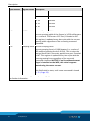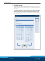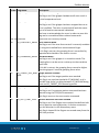
1
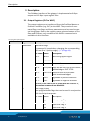
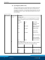
original software manual Fieldbus Interface WSG Software manual Superior Clamping and Gripping Imprint Imprint Copyright: This manual remains the copyrighted property of SCHUNK GmbH & Co. KG. It is solely supplied to our customers and operators of our products and forms part of the product. This documentation may not be duplicated or made accessible to third parties, in particular competitive companies, without our prior permission. Technical changes: We reserve the right to make alterations for the purpose of technical improvement. Document number: 0389732 Edition: 01.00 |18/09/2015|en © SCHUNK GmbH & Co. KG All rights reserved. Dear customer, congratulations on choosing a SCHUNK product. By choosing SCHUNK, you have opted for the highest precision, top quality and best service. You are going to increase the process reliability of your production and achieve best machining results – to the customer's complete satisfaction. SCHUNK products are inspiring. Our detailed assembly and operation manual will support you. Do you have further questions? You may contact us at any time – even after purchase. Kindest Regards Yours SCHUNK GmbH & Co. KG Spann- und Greiftechnik Bahnhofstr. 106 – 134 D-74348 Lauffen/Neckar Tel. +49-7133-103-0 Fax +49-7133-103-2399 [email protected] www.schunk.com 2 01.00|WSG |en Table of contents Table of contents 1 Introduction ............................................................................................................. 4 2 Interface................................................................................................................... 5 2.1 PROFIBUS .................................................................................................................. 5 2.1.1 Installing the GSD file .................................................................................... 5 2.1.2 Configuration ................................................................................................ 6 2.2 PROFINET .................................................................................................................. 6 2.2.1 Installing the GSDML file ............................................................................... 6 2.2.2 Configuration ................................................................................................ 7 3 Description ............................................................................................................... 8 3.1 Output Registers (PLC to WSG) ................................................................................ 8 3.2 Input Registers (WSG to PLC) ................................................................................. 10 3.3 Diagnosis Messages PROFIBUS............................................................................... 13 4 Commands .............................................................................................................. 14 4.1 MOVE - Move the gripper fingers .......................................................................... 14 4.2 GRASP - Grasp a part .............................................................................................. 15 4.3 RELEASE - Release a part ........................................................................................ 16 4.4 HOMING - Referencing the gripper fingers ............................................................ 17 4.5 STOP/ACK - Stop movement or acknowledge a FAST STOP .................................. 18 4.6 FAST STOP - Raise a Fast Stop with turning off the motor ..................................... 19 4.7 JOG+ and JOG- - Jog Mode in positive and negative direction .............................. 20 5 Fieldbus Monitor ..................................................................................................... 22 5.1 Appendix A: Status Codes....................................................................................... 23 5.2 Appendix B: System State Flags.............................................................................. 24 5.3 Appendix C: Grasping States .................................................................................. 27 5.4 Appendix D: Demo Program ................................................................................... 28 01.00|WSG |en 3 Introduction 1 Introduction The following manual contains the description of the fieldbus interfaces PROFIBUS and PROFINET. This manual assumes that you are familiar with the PROFIBUS and/or PROFINET technology and the Siemens SIMATIC software. The WSG family of grippers provides interfaces to CAN-bus, PROFIBUS DP V0 and/or PROFINET, dependent on the gripper type. All grippers contain an Ethernet TCP/IP as parametrisation and communication interface. The description of the parametrisation and communication interfaces CAN-bus and Ethernet TCP/IP are contained in the software manual Command Set Reference. Further information is contained in the assembly and operating manual of the gripper. 4 01.00|WSG |en Interface 2 Interface Each gripper is displayed via an I/O register space which is periodically synchronized with the PROFIBUS master or the PROFINET controler (e.g. PLC). Interfaces are selected and configured via the web interface of the gripper. To enable this function, the gripper must be connected with a local company network or directly connected with a network interface of a computer or laptop. Further information can be found in the assembly and operating manual of the gripper and in the software manual Command Set Reference. 2.1 PROFIBUS PROFIBUS and PROFINET use the same I/O register. Each PROFIBUS slave has an I/O register space that is periodically updated and read by the PROFIBUS Master. The I/O-Space of the gripper is preconfigured at master-side by using the device profile. Further information on the particular I/O register, ( 3, Page 8). 2.1.1 Installing the GSD file NOTE The GSD file can installed in Siemens STEP7 v11.0 (TIA) and newer The GSD file is provided as a ZIP-compressed package that contains the following files: • WEIS5555.gsd (device description file) • WSG_D.bmp (visualization file) • WSG_R.bmp (visualization file) • WSG_S.bmp (visualization file) • install.txt (installation notes) Follow these steps to install the GSD file in Siemens STEP7 11.0: 1 Unzip the package and store the files above to your disk 2 In the Siemens TIA, open the project view. 3 Select “Options -> Install general station description file (GSD) ” 4 Point to the location where you stored the unzipped package on your disk. 5 You will now find the WSG in the Device Catalog under “Other field devices -> PROFIBUS-DP -> Drives -> Weiss Robotics GmbH & Co. KG” 01.00|WSG |en 5 Interface 2.1.2 Configuration To be able to use the interface PROFIBUS, it first has to be selected via the web interface. The station address of the PROFIBUS is preset to 7 but may be changed via the web interface. Further information is contained in the assemply and operating manual of the gripper. 2.2 PROFINET PROFINET and PROFIBUS use the same I/O register space layout. The I/O space is periodically updated and uses a pre-defined profile which is installed at the PROFINET-controller (e.g. PLC). The profile can be found on the Product CD or downloaded from the web interface. The I/O register space is described in detail in ( 3, Page 8). 2.2.1 Installing the GSDML file NOTE The GSDML- file can be installed in Siemens STEP7 v11.0 (TIA) and newer. The GSDML file is provided as a ZIP-compressed package that contains the following files: • GSDML-VX.XX-Weiss Robotics-WSG-XXXXXXXX.gsdml (device description file) • GSDML-02A2-0001-WSG.bmp (visualization file) Follow these steps to install the GSD file in Siemens STEP7 11.0: 1 Unzip the package and store the files above to your disk 2 In the Siemens TIA, open the project view. 3 Select “Options -> Install general station description file (GSD) ” 4 Point to the location where you stored the unzipped package on your disk. 5 You will now find the WSG in the Device Catalog under “Other field devices -> PROFINET IO -> I/O -> Weiss Robotics GmbH & Co. KG” 6 01.00|WSG |en Interface 2.2.2 Configuration To use the WSG’s PROFINET interface, it must first be enabled via the device’s web interface. Further configuration options can be set either directly on the WSG using its web interface to change IP address or PROFINET device name. However, PROFINET also allows various configuration options to be set remotely using an engineering tool like e.g. Siemens STEP7. Please refer to the documentation of your engineering tool. NOTE Changing the WSG’s IP address settings remotely using an engineering tool. The device’s web interface might become inaccessible if the PROFINET connection gets lost. It is strongly recommended to change these settings only via the WSG’s web interface. Further information is contained in the assembly and operating manual of the gripper. 01.00|WSG |en 7 Description 3 Description The Fieldbus interface of the gripper is implemented as 8-Byte output and 12-Byte input register files. 3.1 Output Registers (PLC to WSG) The output registers are transferred from the Profibus Master or Profinet Controller (e.g. PLC) to the WSG. They consist of command flags, user flags and three parameters and are used to control the gripper. Due to the register-space-oriented nature of Profibus and Profinet, only a subset of the WSG’s command set is available via this interface. Grouping of Output Registers Byte Number Register Name Description 0 CMDFLAGS Command Flags A command is issued when changing the corresponding bit from 0 to 1 (raising edge), ( 4, Page 14). Bit Index: Name Description Bit 0: MOVE Move the gripper fingers Bit 1: GRASP Grasp a part Bit 2: RELEASE Release a part Bit 3: HOMING Home the gripper Bit 4: STOP/ACK Stop, but do not turn off the motor / Acknowledge a FAST STOP Bit 5: FASTSTOP Stop and turn off the motor. must be acknowledged Bit 6: JOG+ Jog-Mode in positive direction Bit 7: JOG- Jog-Mode in negative direction NOTICE! If the FASTSTOP or STOP/ACK bit is set to ‘1’, the motion commands are disabled. 1 IF User Flags (input) Free programmable flags that can be used in conjunction with the Script Interpreter. 8 01.00|WSG |en Bit Index: Name Description 0 IF1 Input User Flag 1 1 IF2 Input User Flag 2 2 IF3 Input User Flag 3 3 IF4 Input User Flag 4 Description Byte Number 2..3 Register Name Description WIDTH 4 IF5 Input User Flag 5 5 IF6 Input User Flag 6 6 IF7 Input User Flag 7 7 IF8 Input User Flag 8 Command parameter “Width” New finger opening width in 1/100 millimeters (i.e. a value of 1220 means 12.20 mm). Encoded as INT (signed). 4..5 SPEED Command parameter “Speed” Current movement speed in 1/100 millimeters per second (i.e. a value of 3005 means 30.05 mm/s), given as finger speed relative to each other. Encoded as WORD (unsigned). NOTICE! Setting this parameter to a value beyond the system limits and triggering a motion-related function using it raises a FAST STOP. 6..7 FORCELIMIT Command parameter “Force Limit” New grasping force limit in 1/100 Newton (i.e. a value of 1050 means 10.50 N). The grasping force is twice the nominal force that is applied to the part to be grasped. Encoded as INT (signed), only positive values are allowed. NOTICE! Setting this parameter to a value beyond the system limits and triggering a motion-related function using it raises a FAST STOP. To initiate a command, the command parameters have to be set up and the respective command flag has to be changed from 0 to 1 (i.e. a raising transition). Jog Mode flags are level-sensitive. A detailed description of the specific commands can be found in ( 3.2, Page 10). NOTE If more than one command flag was changed simultaneously, only the command with the lowest bit number is executed (i.e. setting both MOVE and GRASP flags from 0 to 1 will result in a MOVE command). NOTICE Changing parameters while fingers are moving (i.e. MOVING in the system flags is 1) will result in a FAST STOP. 01.00|WSG |en 9 Description 3.2 Input Registers (WSG to PLC) The input register space is transferred from the WSG to the Profibus Master or Profinet Controller each cycle. It contains the current gripper parameters, its operating and grasping state, user defined flags as well as a status code representing the result of the last command. grouping Input Register Byte Number Register Name Description 0 GSTATE Grasping State These flags encode the current grasping state as below and are intended to control and monitor the grasping process: 1 OF Bite Index: Name Description Bit 0: IDLE Waiting for new command Bit 1: GRASPING Fingers moving towards the part Bit 2: NO_PART No part found Bit 3: PART_LOST Part was grasped but then lost Bit 4: HOLDING Holding a part Bit 5: RELEASING Fingers moving away from the part Bit 6: POSITIONING Fingers moving due to a pre-position command (MOVE) Bit 7: ERROR An error occured User Flags (output) Freely programmable flags that can be used to interact between the PLC code and a running WSG Script. 10 01.00|WSG |en Bit Index: Name Description Bit 0: OF1 Output User Flag 1 Bit 1: OF2 Output User Flag 2 Bit 2: OF3 Output User Flag 3 Bit 3: OF4 Output User Flag 4 Bit 4: OF5 Output User Flag 5 Description Byte Number 2..5 Register Name Description SYSSTATE Bit 5: OF6 Output User Flag 6 Bit 6: OF7 Output User Flag 7 Bit 7: OF8 Output User Flag 8 System State Current system state of the gripper encoded as a bit vector ( 5.2, Page 24). This register is updated every bus cycle with the system state flags regardless of the currently processed command. Please note that the system state flags should not be used to control the grasping process. Use the grasping state instead. Bit Index: Name Bit 0 REFERENCED Bit 1 MOVING Bit 2 BLOCKED_MINUS Bit 3 BLOCKED_PLUS Bit 4 SOFT_LIMIT_MINUS Bit 5 SOFT_LIMIT_PLUS Bit 6 AXIS_STOPPED Bit 7 TARGET_POS_REACHED Bit 8 OVERDRIVE_MODE2 Bit 9 FORCECNTL_MODE Bit 10 reserved Bit 11 reserved Bit 12 FAST_STOP Bit 13 TEMP_WARNING Bit 14 TEMP_FAULT Bit 15 POWER_FAULT Bit 16 CURR_FAULT Bit 17 FINGER_FAULT Bit 18 CMD_FAILURE Bit 19 SCRIPT_RUNNING Bit 20 SCRIPT_FAILURE Bit 21 reserved Bit 22 reserved Bit 23 reserved Bit 24 reserved 01.00|WSG |en 11 Description Byte Number 6..7 Register Name Description WIDTH Bit 25 reserved Bit 26 reserved Bit 27 reserved Bit 28 reserved Bit 29 reserved Bit 30 reserved Bit 31 reserved Current Opening Width Current opening width of the fingers in 1/100 millimeters (i.e. a value of 1220 means 12.2 mm). Encoded as INT. This register is updated every bus cycle with the current opening width regardless of the currently processed command. 8..9 Grasping Force Current Grasping Force Current grasping force in 1/100 Newton (i.e. a value of 405 means a grasping force of 40.5 N). This is twice the nominal force that is currently applied to a part. Encoded as INT. This register is updated every bus cycle with the current grasping force regardless of the currently processed command.NOTICE! If no Force Measurement Finger is installed on the WSG, this value is approximated using the motor current. 10..11 Status Code Result of the last Command This field holds its state, until a new command is issued ( 5.1, Page 23). 2 Overdrive mode is not supported by all WSG grippers. Please refer to the User’s Manual for further information. 12 01.00|WSG |en Description 3.3 Diagnosis Messages PROFIBUS If at least one of the following error-related flags of its system state was raised (i.e. changes from 0 to 1), the gripper will send diagnosis messages as the first double word to the PROFIBUSMaster. The diagnosis messages containing the current system state flags. • SF_SOFT_LIMIT_MINUS • SF_SOFT_LIMIT_PLUS • SF_FAST_STOP • SF_TEMP_FAULT • SF_POWER_FAULT • SF_CURR_FAULT • SF_FINGER_FAULT • SF_CMD_FAILURE • SF_SCRIPT_FAILURE More detailed description of these flags, ( 5.2, Page 24). The format of the diagnosis message Byte Number Description 0..3 Standard Diagnostic Data Diagnostic Data as defined by the PROFIBUS Specification 4..5 Slave Ident-No. Slave Identification Number. This is 0x5555 for the WSG. 6 Length of Diagnostic Message Diagnosis messages of the WSG are always 10 Bytes = 0x0A. 7..10 System State Current system state of the gripper encoded as a bit vector. Same coding as SYSSTATE register. 10..15 reserved This area is reserved for future use. 01.00|WSG |en 13 Commands 4 Commands 4.1 MOVE - Move the gripper fingers This command can be used to position the gripper fingers. To move the gripper fingers to a defined width before issuing a grasp command, a prepositioning may be initiated via this command. The command is intended to speed up grasping of sensitive parts when the gripper fingers have to travel a larger distance due to process constraints. MOVE can only be issued if the gripper is idle, i.e. grasping state is IDLE. Command Flag Position: Bit 0 Parameters used: WIDTH, SPEED Status Code The STATUS CODE register is set to E_CMD_PENDING upon start of the movement and set to the command’s result when it has finished. Grasping State (GSTATE) The grasping state changes to POSITIONING when starting to move and back to IDLE when finished. In case of an error, the grasping state is set to ERROR. System State (SYSSTATE) Various transitions will occur. You should use the GSTATE register to evaluate the current state of the grasping process, unless you have very special requirements. 14 01.00|WSG |en Commands 4.2 GRASP - Grasp a part Grasp a part using its nominal width, the speed and the force limit at which the part should be grasped. When the command is issued, the gripper moves its fingers to the nominal part width and tries to clamp the expected part with the previously set grasping force. If the gripper can establish the desired grasping force within the defined clamping travel, a part is grasped. If the fingers fall through the clamping travel without establishing the grasping force, no part was found and the grasping state is updated accordingly. The clamping travel can be set using the WSG’s web interface. The grasping state is updated with the result of this operation (either PART_HOLDING or NO_PART) as well as the grasping statistics. If no part was found, the command’s result is set to E_CMD_FAILED. After successfully grasping a part, the integrated part monitoring is enabled which supervises the grasping force. If a part is removed from the gripper before issuing the RELEASE command, the gripper detects it and changes the grasping state to PART_LOST. NOTE You may reduce the grasping speed with sensitive parts to limit the impact due to the mass of the gripper fingers and the internal mechanics. Command Flag Position: Bit 1 Parameters used: WIDTH, SPEED, FORCELIMIT Status Code: The STATUS CODE register is set to E_CMD_PENDING upon start of the movement and set to the command’s result when it has finished. Grasping State (GSTATE): During finger movement, the grasping state is set to GRASPING. If a part was found, it changes to HOLDING. If no part was found, the Grasping State is set to NO_PART. If a part was removed after it was clamped, the grasping state is set to PART_LOST. In case of an error, the grasping state is set to ERROR. System State (SYSSTATE): Various transitions will occur. You should use the GSTATE register to evaluate the current state of the grasping process, unless you have very special requirements. 01.00|WSG |en 15 Commands 4.3 RELEASE - Release a part This command is used to release a part by opening the fingers with a given speed and width. The part will not be pinched. This is ensured by successively increasing the internal force limit only when moving away from it. The part monitoring is disabled before releasing it. The gripper’s nominal force is used for release. Command Flag Position: Bit 3 Parameters used: WIDTH, SPEED Status Code: The STATUS CODE register is set to E_CMD_PENDING upon start of the movement and set to the command’s result when it has finished. Grasping State (GSTATE): During finger movement, the grasping state is set to RELEASING. When the end position is reached, the grasping state is set to IDLE. In case of an error, the GSTATE is set to ERROR. System State (SYSSTATE): Various transitions will occur. You should use the GSTATE register to evaluate the current state of the grasping process, unless you have very special requirements. 16 01.00|WSG |en Commands 4.4 HOMING - Referencing the gripper fingers This command provokes a homing to reference the position of the gripper fingers. A homing is necessary before executing any movement commands. If homing is carried out in the direction in which a better positioning accuracy is required, the best positioning result is achieved. During homing, the fingers will move to the mechanical end stop. The homing sequence has to be configured on the Settings -> Motion Configuration page of the web interface. You can set the direction of homing (inbound or outbound) as well as enable automatic homing on startup. NOTE During homing, soft limits are disabled. Obstacles in the movement range of the fingers and collisions with these during homing may result in a wrong reference point for the finger position! Command Flag Position: Bit 3 Parameters used: none Status Code: The STATUS CODE register is immediately set to E_CMD_PENDING and to the command’s result when it has finished. Grasping State (GSTATE): During homing, the grasping state is IDLE. System State (SYSSTATE): During movement, the MOVING flag is set to 1. If the gripper is referenced, the REFERENCED flag is set to 1. 01.00|WSG |en 17 Commands 4.5 STOP/ACK - Stop movement or acknowledge a FAST STOP With this command any pending movement stops immediately without disabling the drive. When stopping during holding a workpiece (i.e. the grasping state is HOLDING), the part monitor will be disabled and the grasping force will not be applied anymore. If the WSG is in FAST STOP mode, a transition from 0 to 1 is required on this flag to acknowledge and to return in normal operating mode. You have to reset the FASTSTOP flag before acknowledging it! Command Flag Position: Bit 4 Parameters used: none Status Code: The STATUS CODE register is set to E_SUCCESS. Grasping State (GSTATE): The grasping state is set to IDLE. System State (SYSSTATE): The AXIS_STOPPED flag is set to 1. If acknowledging a FAST STOP, the FASTSTOP flag is cleared. 18 01.00|WSG |en Commands 4.6 FAST STOP - Raise a Fast Stop with turning off the motor This function is similar to an “Emergency Stop”. It immediately stops any movement the fastest way, disables the drive and prevents further motion-related commands from being executed. The FAST STOP state can only be left by issuing a FAST STOP Acknowledge ( 4.5, Page 18). All motion-related commands are prohibited during FAST STOP and will produce an E_ACCESS_DENIED error. The FAST STOP state is indicated in the system flags and logged in the system’s log file. The FAST STOP command should in general be used to react on certain error conditions. To simply stop the current movement, you may want to use the STOP command instead. NOTE The drive can be enabled again using the web interface. However, it is required to reset the FAST STOP flag on the PROFIBUS interface to enable motion-related commands again. Command Flag Position: Bit 5 Parameters used: none Status Code: The STATUR CODE register is set to E_SUCCESS. Grasping State (GSTATE): The grasping state is set to IDLE. System State (SYSSTATE): The FASTSTOP flag is set to 1. 01.00|WSG |en 19 Commands 4.7 JOG+ and JOG- - Jog Mode in positive and negative direction This command is used to move the gripper fingers manually to set up a process. The Jog Flags are evaluated level-sensitive and allow a constant speed drive of the fingers using two switches on the PLC. Interpretation of the Flags JOG+ JOG- Movement direction 0 0 Jog Mode is disabled* 1 0 positive with SPEED 0 1 negative with SPEED 1 1 Stop *If the Jog flags change to both 0, the Jog mode is left and the drive is stopped. The force limit (current controlled only) as well as the speed can be passed as parameters. You may consider using a hand wheel to control them. Be aware that high movement speed may interfere with a low force limit setting. NOTE In contrast to other motion-related commands, the SPEED Parameter can be set to 0 resulting in an internal clamping of the value to the minimum gripper speed. NOTE The Jog Mode is intended only to set up a process. Do not use the Jog Mode in normal operation of the gripper! Command Flag Position: Bit 6 and 7 Parameters used: SPEED, FORCELIMIT Status Code The status code register is set to E_CMD_PENDING upon start of the movement and set to the command’s result when it has finished. 20 01.00|WSG |en Commands Grasping State During finger movement, the grasping state is set to RELEASING. When the end position is reached (or in case of an error), the grasping state is set to IDLE. System State Various transitions will occur. You should use the grasping state to evaluate the current state of the grasping process, unless you have very special requirements. 01.00|WSG |en 21 Fieldbus Monitor 5 Fieldbus Monitor The gripper has a built-in Fieldbus Monitor that can be accessed via the web interface (select “Diagnosis -> Fieldbus Monitor” from the menu). The monitor displays the current content of the input and output registers and gives some basic information about the bus state, thus making it easy to embed it in a Profibus or Profinet based industrial environment. 22 01.00|WSG |en Fieldbus Monitor 5.1 Appendix A: Status Codes Status Symbol name Code 0 E_SUCCESS Description 1 E_NOT_AVAILABLE Function or data is not available 2 E_NO_SENSOR No measurement converter is connected 3 E_NOT_INITIALIZED Device was not initialized 4 E_ALREADY_RUNNING The data acquisition is already running 5 E_FEATURE_NOT_SUPPORTED The requested feature is currently not available 6 E_INCONSISTENT_DATA One or more parameters are inconsistent 7 E_TIMEOUT Timeout error 8 E_READ_ERROR Error while reading data 9 E_WRITE_ERROR Error while writing data 10 E_INSUFFICIENT_RESOURCES No more memory available 11 E_CHECKSUM_ERROR Checksum error 12 E_NO_PARAM_EXPECTED A Parameter was given, but none expected 13 E_NOT_ENOUGH_PARAMS Not enough parameters for executing the command 14 E_CMD_UNKNOWN Unknown command 15 E_CMD_FORMAT_ERROR Command format error 16 E_ACCESS_DENIED Access denied 17 E_ALREADY_OPEN Interface is already open 18 E_CMD_FAILED Error while executing a command 19 E_CMD_ABORTED Command execution was aborted by the user 20 E_INVALID_HANDLE Invalid handle 21 E_NOT_FOUND Device or file not found 22 E_NOT_OPEN Device or file not open 23 E_IO_ERROR Input/Output Error 24 E_INVALID_PARAMETER Wrong parameter 25 E_INDEX_OUT_OF_BOUNDS Index out of bounds 26 E_CMD_PENDING No error, but the command was not completed, yet. Another return message will follow including a status code, if the function has completed. 27 E_OVERRUN Data overrun 28 E_RANGE_ERROR Range error 29 E_AXIS_BLOCKED Axis blocked 30 E_FILE_EXISTS File already exists No error occurred, operation was successful 01.00|WSG |en 23 Fieldbus Monitor 5.2 Appendix B: System State Flags The system state flags are arranged as a 32-bit wide integer value that is provided via the Profibus Input Registers. Each bit has a special meaning listed below. Bit No. Flag Name Description D31..2 reserved 1 These bits are currently unused. D20 Script Error. SF_SCRIPT_FAILURE The flag is set if an error occurred while executing a script and the script has been aborted. The flag is reset whenever a script is started. D19 SF_SCRIPT_RUNNING A script is currently running The flag is set if a script is executed. The flag is reset if the script either terminated normally, a script error occurred or the script has been terminated manually by the user. D18 SF_CMD_FAILURE Command Error The flag is set if the last command returned an error. D17 SF_FINGER_FAULT Finger Fault The flag is set if the status of at least one finger is set from OPERATING to NOT CONNECTED. Please check the finger flags for a more detailed error description. D16 SF_CURR_FAULT Engine Current Error The flag is set if the engine has reached its maximum thermal power consumption. At the same time a FAST STOP is set. The flag will be reset automatically as soon as the engine has recovered. The FAST STOP has to be acknowledged. D15 SF_POWER_FAULT Power Error The flag is set if the power supply is outside the valid range. The power supply has to be checked and adapted if necessary. D14 SF_TEMP_FAULT Temperature Error The gripper hardware has reached a critical temperature level. All motion-related commands are disabled until the temperature falls below the critical level. 24 01.00|WSG |en Fieldbus Monitor Bit No. Flag Name Description D13 Temperature Warning SF_TEMP_WARNING The flag is set if the gripper hardware will soon reach a critical temperature level. D12 SF_FAST_STOP Fast Stop The flag is set if the gripper has been stopped due to an error condition. The drive is switched off and the execution of all motion commands is disabled. You have to acknowledge the error in order to reset this flag and to re-enable motion-related commands. D11..10 reserved D9 These bits are currently unused. SF_FORCECNTL_MODE Force Control Mode The flag is set if the true force control is currently enabled by using the installed force measurement finger. If this flag is not set, the grasping force is controlled by approximation based on the motor current. D8 SF_OVERDRIVE_MODE Overdrive Mode1. The flag is set if the gripper is in overdrive mode. The grasping force can be set to a value up to the overdrive force limit. If this bit is not set, the grasping force cannot be higher than the gripper’s nominal grasping force value. D7 SF_TARGET_POS_REAC Target position reached HED The flag is set if the target position was reached. This flag is not synchronized with SF_MOVING, so it is possible that there is a delay between SF_MOVING being reset and SF_TARGET_POS becoming active. D6 SF_AXIS_STOPPED Axis stopped The flag is set if a previous motion command has been aborted using the STOP/ACK command. This flag is reset on the next motion command. D5 SF_SOFT_LIMIT_PLUS Positive direction soft limit reached The flag is set if the fingers have reached the defined soft limit in positive moving direction. A further movement into this direction is not allowed any more. This flag is cleared if the fingers are moved away from the soft limit position. 01.00|WSG |en 25 Fieldbus Monitor Bit No. Flag Name D4 Description SF_SOFT_LIMIT_MINUS Negative direction soft limit reached The flag is set if the fingers have reached the defined soft limit in negative moving direction. A further movement into this direction is not allowed any more. This flag is cleared if the fingers are moved away from the soft limit position. D3 SF_BLOCKED_PLUS Axis is blocked in positive moving direction The flag is set if the axis is blocked in positive moving direction. The flag is reset if either the blocking condition is resolved or a stop command is issued. D2 SF_BLOCKED_MINUS Axis is blocked in negative moving direction The flag is set if the axis is blocked in negative moving direction. The flag will be reset if either the blocking condition is resolved or a stop command is issued. D1 SF_MOVING The Fingers are currently moving This flag is set whenever a movement is started, e.g. MOVE command. The flag will reset automatically as soon as the movement stops. D0 SF_REFERENCED Fingers Referenced The flag is set when the gripper was referenced by a HOMING command. Only after homing motion commands can be executed. 3 Overdrive mode is not supported by all grippers. Please refer to the assembly and operating manual of the gripper for further information. 26 01.00|WSG |en Fieldbus Monitor 5.3 Appendix C: Grasping States The following diagram illustrates the grasping states and transitions as intended to be used in normal operation. 01.00|WSG |en 27 Fieldbus Monitor 5.4 Appendix D: Demo Program NOTE The demo project is intended for testing purposes only. Do not use it in any production environment. The gripper is provided with a simple demo project for Siemens SIMATIC S7-1200 controls. The program can be downloaded from the CD. The program has been implemented and tested on a CPU of type 1212C with the Profibus module CM1243- 5 using the Siemens STEP7 Basic v11.0 SP2 (TIA Portal) project environment. It will execute an endless loop of a simple gripping cycle, consisting of prepositioning the gripper jaws, grasping a part, releasing and returning to the start position. If a part is detected, the gripper will hold it for a short moment. In case of an error, the gripper will execute a homing sequence and restart from the beginning. Please note that the gripper must be referenced before running the program. The PLC is configured in the project to use IP address 192.168.1.250 and Profibus address 2. The gripper is expected to use Profibus address 7 (default). These settings may be changed according to your requirements. NOTE It might be useful to open the Fieldbus Monitor on the gripper’s web interface when running the program to get more information on possible problems. 28 01.00|WSG |en