1
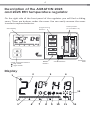
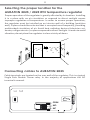
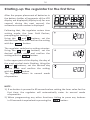
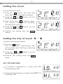
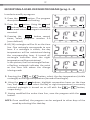
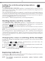
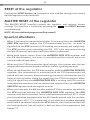
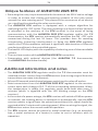
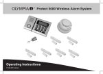
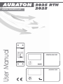
User Manual
www.auraton.pl
3
Thank you for purchasing this modern, advanced, microprocessor-based
temperature regulator AURATON 2025 / AURATON 2025 RTH.
4 independently settable temperatures:
Day, night, anti-freeze, vacation.
Operation under the load of up to 16 A.
The AURATON RTH receiver is equipped with a relay capable
of operating with the load of up to 16 A. Its low-sparking technique
of switching mains voltage contributes to the low wear of relay
contacts.
Interference-free communication between devices.
The transmitter and the receiver from the AURATON 2025 RTH
set communicate at the frequency of 868 MHz. Very short,
encrypted data transmission packets (approx. 0.004 s) ensure very
efficient and interference-free operation of the device.
Backlit LCD display
The backlit LCD display allows for supervising operation
of the device even in a poorly lit room.(3 selectable backlight
colours)
Optional elements of the system
AURATON H-1
Window handle (sold separately)
A window handle, equipped with a position sensor and
a transmitter, is an optional element of the system. This way the
handle provides information about the state of the window.
The handle also differentiates between 4 widow positions:
opened, closed, pivoted and trickle ventilated (microventilation). The handle transmits information to the RTH
receiver that controls the relay, e.g. switching off a heater in the
event of opening the window or lowering the temperature down
to 3 °C to conserve energy. One RTH receiver operates with max
25 handles.
AURATON T-2
Thermometer (sold separately)
An optional element of the system allowing for controlling
temperature in a room other than that with the AURATON 2025
RTH regulator.
4
Description of the AURATON 2025
and 2025 RTH temperature regulator
On the right side of the front panel of the regulator you will find a sliding
cover. There are buttons under the cover. You can easily remove the cover
in order to replace batteries.
battery holder
(2 x AA LR6 1.5 V)
programming
buttons
LCD display
RESET
button
mode selection buttons
day mode
night mode
fastening
hole
microswitches
Display
2
1
4
3
13
5
6
7
8
9
10
11
12
5
1. Day of the week
Indicates the current day of the week. Every day is assigned a number.
2. Temperature
In the normal mode of operation, the regulator displays the temperature
in the room it is installed in.
3. Temperature unit
Informs whether the temperature is displayed in degrees Celsius (°C)
or in degrees Fahrenheit (°F).
4. Clock
Time is displayed in the 24-hours format.
5. Time line
A program progress indicator. It is a line divided into 24 sections.
Each section corresponds to one hour. This line shows how a given program
will be executed. (See chapter: “Time line”)
6. Day mode indicator ( )
Indicates that at the moment, the regulator operates in day mode.
(See chapter: “Temperature programming”)
7. Night mode indicator ( )
Indicates that at the moment, the regulator operates in night mode.
(See chapter: “Temperature programming”)
8. Anti-freeze mode indicator ( )
Indicates that at the moment, the regulator operates in anti-freeze mode.
(See chapters: “Temperature programming” and “Anti-freeze mode”)
9 . Manual control indicator ( )
Appears when you temporarily leave the mode of operation
of the programmed mode (See chapters: “Manual control” and “Vacation
mode”)
10. Transmission symbol (AURATON 2025 RTH)
Indicates ongoing communication with the RTH receiver.
11. Regulator power-on symbol
Spinning fan informs about the state of operation of a controlled device
and is visible only when the device is switched on (boiler, heater etc.).
12. Program number
The number of the currently executed program is displayed. (See chapters:
“Factory programs” and “Week-wise programming”)
13. Low battery ( )
This indicator will be visible when the battery voltage drops to the minimal
allowable level. In such an event, replace the batteries as soon as possible.
NOTE: In order to preserve the programmed parameters, the duration of
the replacement operation must not to exceed 30 seconds.
6
Microswitches
Under the cover, you will find 4 microswitches responsible for:
display switched on
in a dark room
display switched off
in a dark room
no delay
(AURATON 2025)
hysteresis
0,8°C
90 s delay
hysteresis
0,4°C
(AURATON 2025)
°F
°C
1. Switching the lighting sensor off:
OFF – The display is switched off in a dark room (default setting);
ON – The display is not switched off in a dark room.
2. 90 second delay when switching on (AURATON 2025 only):
OFF – 90 s delay (default setting);
ON – No delay.
The delay prevents too frequent switching of the output device,
e.g. due to a temporary draft of air.
3. Changing the hysteresis:
OFF – 0,4°C (default setting);
ON – 0,8°C.
E.g. for 0.4 °C and the temperature set at 20 °C, switching on and off will
be performed at 19.8 °C and 20.2 °C, respectively. For 0.8 °C and
the temperature set at 20 °C, switching on and off will be performed
at 19.6 °C and 20.4 °C, respectively.
4. Selecting temperature units:
OFF – degrees Celsius (°C) (default setting);
ON –degrees Fahrenheit (°F).
7
Description of the AURATON RTH receiver
The AURATON RTH receiver cooperates with the AURATON 2025 RTH wireless
receiver. The receiver is installed on the heating or air conditioning device and can
operate under the load of 16 A.
hole for fastening the receiver
to the wall with a screw
cable tie clamp
control connection terminal
(a terminal for fastening a two-core
cable of the heating or air conditioning
device to be controlled
button for pairing devices
with the RTH receiver
button for deregistering
already paired devices
cable tie clamp
power supply terminal
~230 VAC
LED indicating operation
of the device
legend
AURATON RTH
hole for fastening the receiver
to the wall with a screw
Legend - description of LED signalling
The LED light’s green – the output device is off (the contacts COM
and NC are closed).
The LED light’s red – the output device is on (the contacts COM and
NO are closed).
The LED flashes green – the RTH receiver awaits the device
to be paired (chapter: “Pairing the AURATON 2025 RTH wireless
regulator and the RTH receiver”).
The LED flashes red – the RTH receiver awaits the device
to be deregistered (chapter: “Deregistering the regulator from the
RTH receiver”).
The LED flashes alternating red and green:
ALARM - the RTH receiver has lost connection with one of the paired
devices (chapter “Special situations”).
RESET - receiver deregisters all previously paired devices - (chapter
“Deregistering all devices paired with the RTH receiver”).
8
Selecting the proper location for the
AURATON 2025 / 2025 RTH temperature regulator
Proper operation of the regulator is greatly affected by its location. Installing
it in a place with no air circulation or exposed to direct sunlight causes
improper regulation of temperature. In order to ensure proper operation,
the regulator must be installed on an interior wall of a building (partition
wall). A place should be selected that is occupied most frequently, providing
undisturbed circulation of air. Avoid heat radiating devices (television set,
heater, refrigerator etc.) or places exposed to direct sunlight. In order to avoid
vibration, do not place the regulator in close vicinity of doors.
Connecting cables to AURATON 2025
Cable terminals are located on the rear wall of the regulator. This is a typical
Single Pole Double Throw relay. In the majority of applications the NC
terminal is unused.
COM
NO
NC
9
Fastening the temperature regulator to the wall
1.Drill two holes 6 mm in diameter in the wall (use the template attached
to the manual to mark the spacing between these holes).
2.Insert plastic wall plugs (included in the kit).
3.Screw in the left screw with a 3 mm clearance.
4.Put the regulator over the screw head and slide it to the left (pay attention
to the key-hole in the rear wall of the regulator).
5.Screw in the right screw, making sure it holds the regulator securely.
NOTE: If the wall is wooden, there is no need to use wall plugs. In such a case,
drill two holes 2.7 mm in diameter instead of 6 mm, and screw the
screws directly into the wood.
10
Fastening the RTH receiver
NOTE: When installing the AURATON RTH
receiver its power supply must be
disconnected. It is recommended that the
installation is performed by a qualified
specialist.
1. Take off protective covers from the lower
and upper part of the AURATON RTH
receiver.
protective cover
2. Take off cable tie clamps from the lower
and upper part of the AURATON RTH
receiver.
cable tie clamp
3. Connect the heating device to the
control connection terminals of the
AURATON RTH receiver.
Proceed in accordance with the service
manual of the heating device. Most
commonly, the COM (common) and NO
(normally open) terminals.
4. Connect power supply conductors to the
power supply terminals of the AURATON
RTH receiver, observing safety rules.
5. After connecting the conductors, they must
be secured with the cable tie clamps and
reinstall protective covers of the AURATON
RTH receiver.
NOTE:
The permanent electrical system
of a building must include a breaker
and an overcurrent protection.
11
Fastening the RTH receiver to the wall
To fasten the AURATON RTH receiver to the wall:
1) Remove protective covers from the lower and upper part of the regulator.
(See chapter: “Fastening the RTH receiver”).
2) On the wall, mark the location of holes for fastening screws.
3) In marked places, drill holes of a diameter corresponding to the bundled
wall plugs (5 mm).
4) Insert wall plugs into the drilled holes.
5) Screw in the RTH receiver to the wall with screws, making sure they hold the
receiver securely.
hole for fastening
the receiver to the wall with a screw
AURATON RTH
hole for fastening
the receiver to the wall with a screw
NOTE: If the wall is wooden, there is no need to use wall plugs. In such a case,
drill two holes 2.7 mm in diameter instead of 5 mm, and screw
the screws directly into the wood.
NOTE: The RTH receiver cannot be placed in metal containers
(e.g. an assembly box, a metal enclosure of a heater) in order to not to
interfere with its operation.
12
Pairing the AURATON 2025 RTH wireless
temperature regulator with the RTH receiver
NOTE: The AURATON 2025 RTH wireless temperature regulator sold with the
AURATON RTH receiver is already paired. Devices sold separately
require “pairing”.
LED
1. The process of pairing the 2025 RTH regulator with
the RTH receiver is initiated by pressing the left
pairing button (marked with a green triangle - )
on the RTH receiver and holding it for at least
2 seconds, until the LED starts flashing green,
and then releasing the button.
The AURATON RTH receiver waits for pairing
for 120 seconds. After that time, it automatically
returns back to normal operation.
2. On the AURATON 2025 RTH regulator, press the PROG button and hold it for
5 seconds until the transmission symbol (radio) appears on the display. Release
the button - the regulator transmits the pairing signal for 5 seconds.
3. A properly completed pairing process is signalled by the LED on the AURATON
RTH receiver no longer flashing green and the receiver reverting back to normal
operation.
In the event of an error during the pairing process, repeat steps 1 and 2. Should
more errors occur, deregister all devices by executing the RESET function of the RTH
receiver (see “RESET - Deregistering all devices paired with the RTH receiver”)
and attempt to pair the device again.
NOTE: One receiver can have only one temperature regulator assigned.
Deregistering the regulator from the RTH receiver
LED
1. Deregistering the 2025 RTH regulator from the RTH
receiver is initiated by pressing the right deregistering
button (marked with a red triangle - ....) on the
RTH receiver and holding it for at least 2 seconds, until
the LED starts flashing red, and then releasing
the button.
The AURATON RTH receiver waits for deregistering for
120 seconds. After that time, it automatically returns
back to normal operation.
13
2. On the AURATON 2025 RTH regulator, press the PROG button and hold it for
5 seconds until the transmission symbol ( radio) appears on the display. Release
the button - the regulator transmits the pairing signal for 5 seconds.
3. A properly completed deregistering process is signalled by the LED on the
AURATON RTH receiver no longer flashing red and the receiver reverting back
to normal operation.
In the event of an error during the deregistering process, repeat steps 1 and 2.
Should more errors occur, deregister all paired devices (see “RESET - Deregistering
all devices paired with the RTH receiver”) and attempt to pair the device again.
RESET - Deregistering all devices paired
with the RTH receiver
In order to deregister all devices paired with
the RTH receiver, simultaneously press both
the pairing and the deregistering button
(.. and ..) and hold them for at least
5 seconds until the LED flashes alternating
red and green. Then release both buttons.
LED
A properly completed process of
deregistering all devices is signalled after
approx. 2 seconds by the LED colour
changing to green and then switching it off
for a short period of time.
NOTE: If after executing the RESET function the RTH receiver is disconnected
from power supply and then connected again, the receiver will automatically
enter “pairing” mode for 120 seconds. A newly purchased RTH receiver without
any factory-paired devices (i.e. not the one bundled with the regulator) will
behave the same way.
Signalling operation and reception
of data packet
Each radio transmission received by the AURATON RTH receiver from the paired
device is signalled by a temporary change of LED colour to orange. Switching on
the relay is signalled by the LED lit red, whereas switching it off is signalled by the
LED lit green.
14
Starting-up the regulator for the first time
After the proper placement of batteries in
the battery holder, all segments of the LCD
display are displayed (display test) for one
second; during the next second, the
software version number is displayed.
Following that, the regulator enters time
setting mode; the hour field flashes,
prompting for setting it.
Using the ‚,, and ,,,, buttons, set the
desired hour value and confirm the setting
with the OK
button.
The regulator switches to setting minutes.
Using the ,,,,‚ and ,,,, buttons, set the
desired minute value and confirm the
setting with the OK
button.
In the upper part of the display, the day of
the week symbol starts flashing. Using the
,,,‚ and ,,,, buttons, set the desired day
of the week and confirm the setting
with the OK
button.
The regulator enters its normal mode
of operation.
NOTE:
1) If no button is pressed in 60 seconds when setting the hour value for the
first time, the regulator will automatically enter its normal mode
of operation.
2) When programming any other functions, failing to press any buttons
in 10 seconds is equivalent to pressing the OK.
button .
15
Setting the clock
In order to set the clock:
1. Press the T button. The hour field
starts flashing, prompting for setting it.
2. Using the ‚,, and .... buttons, set the
desired hour value.
3. Then press the T
button again.
The minute field starts flashing,
prompting for setting it.
4. Using the ‚.. and ... buttons, set the
desired minute value.
5. Confirm the setting with the
button.
Ok
...
Setting the day of week
In order to set the day of week:
1. Press the D button.
One of the digits representing days
of the week starts flashing, prompting
for setting it.
2. Using the ‚,,, and ..... buttons, set the
desired day of week.
3. Confirm the setting with the
butto .
OK
LO, HI indicator
If measured temperature is lower than 5°C
LCD will display "LO".
If measured temperature is higher than 30°C LCD
will display "HI".
16
Default settings of programs
Monday – Friday:
The heating device maintains day temperature from 05:00 to 08:00
and from 15:00 to 23:00.
Saturday – Sunday
The heating device maintains day temperature from 06:00 to 23:00.
Default temperature setpoints:
Day temperature – 21,0 °C
Night temperature – 19,0 °C
Anti-freeze temperature – 7,0 °C
Programming the day ( ), night (
and anti-freeze ( ) temperatures
)
The AURATON 2025 / AURATON 2025 RTH regulator allows for programming
3 kinds of temperatures:
Day temperature ( ) - from 5 to 30 °C
Night temperature ( ) - from 5 to 30 °C
Antifreeze temperature ( ) - from 4 to 10 °C
In order to set one of the above temperatures:
1. Press the TEMP button.
2. The current temperature setpoint will
appear on the display with the symbol:
– day temperature,
– night temperature,
– anti-freeze temperature.
3. Using the ,,,‚ and ,,,,,, buttons, set the desired temperature setpoint.
4. By pressing the TEMP button, toggle between the available kinds
of temperature to be set ( , ,
);
5. After setting all 3 temperature setpoints, confirm the setting with
the
button .
NOTE: The value of the night temperature setpoint can be equal to or lower
than the value of the day temperature setpoint. It is not possible to
set the night temperature setpoint higher than the day temperature
setpoint.
17
INTRODUCTION TO PROGRAMMING
Time line
The LCD display displays the time line divided into 24 sections, where each
section corresponds to 1 hour of a 24-hour long day.
A black rectangle above a given hour indicates that the day temperature is
maintained, whereas no such a rectangle indicates that the night
temperature is maintained.
An example:
The above picture shows that from 06:00 to 23:00 the regulator controls the
heating device in a manner to maintain the day temperature in the room
(
). From 23:00 to 06:00 the regulator switches over to the night
temperature (
).
Factory programs
In order to let the regulator know when to use the day or the night
temperature, it is necessary to assign an appropriate program to each day
of week. In order to do this, you can use one of the three factory-defined
programs:
Program no. 0 – anti-freezing
A factory program designed for setting the anti-freezing temperature.
Selecting this program causes the maintaining of the anti-freezing
temperature throughout the day.
Program no. 1 – week days
A factory program that cannot be modified. Setting this program causes
the heating devices to maintain the day temperature from 05:00 to 0800
and from 15:00 to 23:00.
Program no. 2 – weekend
A factory program that cannot be modified. Setting this program causes
the heating device to maintain the day temperature from 06:00 to 23:00.
Program no. 3, 4,….,9 – user defined
Programs no. 3 through 9 are user-defined programs. The user can
modify and adapt them at will.
18
PROGRAMMING
Weekly programming
In order to program the regulator, it is necessary to decide on which day of
the week and during what period of time the day temperature should be
maintained. During the remaining time, the night temperature will be
maintained.
An exemplary mode of operation of the regulator from Monday until
Sunday. Besides the defined periods of time, the regulator maintains the
lower night temperature.
Day of week Day temperature
Monday
6:00 – 8:00; 15:00 – 23:00
Tuesday
6:00 – 8:00; 15:00 – 23:00
Wednesday
6:00 – 8:00; 15:00 – 23:00
Thursday
6:00 – 8:00; 15:00 – 23:00
Friday
6:00 – 8:00; 15:00 – 23:00
Saturday
8:00 – 23:00
Sunday
8:00 – 23:00
SELECTING A PROGRAM
In order to select a program:
1. Press the PROG button. The program
description field starts flashing.
2. Press the D button. Using the ,‚,,, and
.... buttons or the D button set the day
of the week when the program should be
executed.
3. Pressing the PROG button several
times, select the desired program
number. Programs no. 0-2 are factorydefined and programs no. 3-9 can be
modified.
4. Confirm the setting with the
button.
OK
5. Return to step 1 and repeat the above procedure for the next day of the
week. Programming can end when each day of week is assigned
an appropriate program.
19
MODIFYING A USER-DEFINED PROGRAM (prog. 3...9)
In order to modify a program:
1. Press the PROG button. The program
description field starts flashing.
2. Press the D button. Using the ‚,,,, and
..... buttons or the D button, set the day
of the week when the program should be
executed.
3. Pressing the PROG button several
times, select programs number 3-9
(user-defined)
4. All (24) rectangles will be lit on the time
line. One rectangle corresponds to one
hour. If a rectangle is visible, the day
temperature will be maintained during
the corresponding hour. A turned off
rectangle indicates that the night
temperature will be maintained.
In the picture, the first rectangle flashes a flashing rectangle indicates the point
on the time line where the change
is being made.
5. Pressing the
or
button, select the day temperature (visible
rectangle) or the night temperature (turned off rectangle).
6. Using the ,,,,,‚and ..... buttons, highlight consecutive hours on the time
line, and for each hour select the day or night temperature (a currently
selected rectangle is turned on or off with the
or
button,
respectively).
7. Having modified the entire time line, save the program with the
button.
OK
NOTE: Once modified, the program can be assigned to other days of the
week by selecting it for that day.
20
Manual control
When, for any reason, you would like to suspend execution of the program for a
certain period of time, e.g. due to a party when you want to maintain the day
temperature until the end of the party, and the regulator has already started
decreasing the temperature down to the night temperature setpoint (“
” is
displayed), perform the following steps:
1. Press the ,,,,,,,,, button. The “ ” will appear on the display. A comfortable
temperature will be maintained until the next temperature change
performed by the program.
2. In order to cancel the above mentioned function, press the OK button
located under the battery cover; the “ ” symbol will disappear.
Similarly, if the program at the moment maintains the day temperature and you
leave your home for a longer period of time, then:
1. Press the ,,,,,,,, button. The “
” will appear on the display. The night
temperature will be maintained until the next temperature change
performed by the program.
2. In order to cancel the above mentioned function, press the OK button.
.
Vacation mode
There are times when we leave our homes for a longer time. In order to avoid
re-programming the entire regulator, vacation mode can be used. This mode
makes the regulator to maintain just one temperature during the entire period
of your absence. It can last for as short as 1 hour, and as long as
99 days.
In order to enter vacation mode:
1. Press the ........ or ........ button and hold
it for 3 seconds. The display shows the
temperature and the flashing time field.
Use this field to set the duration for the
vacation mode.
2. Using the ,,,,‚ and ,,,,,, buttons, set time:
hours (1-23) and then days (1-99). Confirm
the setting with the OKoo. button.
3. The temperature field starts flashing.
Using the ‚,,,,, and ,,,,,, buttons, set the
temperature. Confirm the setting with the
OK button.
If the selection is not confirmed within 10 seconds, the regulator will
automatically enter vacation mode.
In order to leave vacation mode, press the O K button.
NOTE: The vacation temperature is independent of the day, night or antifreezing temperature.
21
Setting the anti-freezing temperature
program
The AURATON 2025 / 2025 RTH regulator is equipped with a setpoint for the
anti-freeze temperature. This setpoint can be set within the range from 4 to
10 °C. (Factory set at 7 °C)
The anti-freezing temperature setpoint is used during a prolonged absence
or outside the heating season and is designed to prevent water in the heating
system from freezing. In order to set the anti-freezing temperature program,
select the program no. 0 for each day of week.
(See chapter: “Weekly programming - selecting a program”)
Heating device run time counter
The AURATON 2025 / 2025 RTH regulator is equipped with a function for
counting the run time of the heating device. The function is activated by
pressing the OK.... button and holding it for 5 seconds.
The display will show information about the accumulated run time since the
last reset of the device.
NOTE: The run time counter counts the time between sending the “switch on
the heating device” signal (displaying the “fan” symbol) and sending the
“switch off the heating device” signal. This time can vary from the actual run
time of the heating device, e.g. due to the fact of using internal thermostats in
heating devices.
Changing the colour or switching off the backlight
In order to change the backlight colour or switch it off in the normal mode
of operation:
1. Press the ,,,,,‚ and ,,,,,, buttons simultaneously and hold them for
5 seconds. The backlight starts flashing.
2. Using the ‚,,,,, and ,,,,,, buttons, change the backlight colour or switch it off.
3. Confirm the change with the OK..... button.
NOTE: If "Low battery" (
) indicator appears on the LCD backlitght function
is inactive to save energy .
Replacing batteries
"Low battery" ( ) indicator appears on the LCD if voltage reached its minimum
level. Replace batteries as soon as possible.
NOTE: To maintain programmed parameters replace batteries within
30 seconds.
22
Cooperation of the RTH
receiver with a heating device
Additional system devices
Basic configuration of devices
AURATON RTH
Receiver connected
to the heating device
AURATON
2025 RTH
Wireless
temperature regulator
AURATON H-1
AURATON T-2
Wireless thermometer Window handle
(sold separately)
(sold separately)
A simplified schematic
of connecting the AURATON RTH
receiver with the heating device
heating device
AURATON RTH
Cooperation of the AURATON RTH receiver with the
AURATON 2025 RTH regulator and/or the AURATON T-2 thermometer
The operation of temperature regulation in the receiver is based on the
binary algorithm (on/off) using one or two sensor elements.
The AURATON 2025 RTH regulator allows for setting and/or monitoring
the temperature.
The AURATON T-2 thermometer provides information about the current
temperature only, without the capability of changing it manually.
A) The manual setpoint – pairing the AURATON 2025 RTH regulator with the
RTH receiver allows for setting the temperature manually and controlling
it in the location of the fastening of the 2025 RTH regulator.
23
B) The remote setpoint – if the T-2 thermometer is additionally paired with
the RTH receiver, the AURATON 2025 RTH regulator retains the capability
of temperature setting, however its control is performed with the paired
T-2 thermometer only. This feature allows for regulating the temperature
in a room other than the one where the AURATON 2025 RTH regulator
is placed.
An example: you want the temperature in the “children’s room” to be
always at 22 °C, however you do not want children to be able
to change it - in that room, you install the T-2 thermometer, and the
AURATON 2025 RTH regulator in e.g. the kitchen. This way the
temperature in the “children’s room” will always be at 22 °C regardless
of temperature fluctuations in the kitchen.
C) The factory setpoint (20 °C) – if the T-2 thermometer is the only device
paired with the RTH receiver, it is not possible to set the temperature
manually, and the RTH receiver maintains the factory temperature
setpoint of 20 °C.
NOTE!
1. The sequence of pairing the AURATON 2025 RTH regulator and the T-2
thermometer is very important. If you want to maintain the remote
setpoint, you must first pair the AURATON 2025 RTH with the RTH
receiver, and then the T-2 thermometer. Reversing the pairing sequence
will cause automatic deregistering of the previously paired T-2
thermometer and entering the mode of operation described in item A.
2. The RTH receiver can operate with one AURATON 2025 RTH regulator
and/or one T-2 thermometer only. Pairing a new regulator causes
deregistering the previously paired regulator and the T-2 thermometer.
Pairing a new T-2 thermometer causes deregistering the previously
paired T-2 thermometer only.
3. The 2025 RTH regulator and/or the T-2 thermometer can operate with an
unlimited number of receivers, e.g. one regulator can simultaneously
control two independent heating devices.
24
Cooperation with the AURATON 2025 RTH regulator and/or
the AURATON T-2 thermometer as well as the AURATON H-1 handles
By default, the AURATON RTH receiver does not have any AURATON H-1
handle or AURATON W-1 window position sensor paired, therefore the relay
is controlled by the paired AURATON 2025 RTH regulator and/or
the AURATON T-2 thermometer. When at least one H-1 handle is paired with
the RTH receiver, the relay is controlled in the following manner:
A) The window is closed or trickle-ventilated (micro-ventilation).
When the H-1 window handles is paired with the receiver, and all
windows are closed or trickle-ventilated, the relay still maintains the
setpoint from the paired AURATON 2025 RTH regulator and/or the
T-2 thermometer.
B) The window is pivoted.
If at least one window is pivoted, the temperature set in the AURATON
2025 RTH regulator is lowered in AURATON RTH receiver down to 3 °C.
This state will be maintained until closing. This state will last until all
windows are closed or trickle-ventilated.
C) The window is opened.
When you open a window equipped with the H-1 handle paired for
longer than 30 seconds, the relay in the AURATON RTH receiver
is switched off, as is the connected heating device. If all the assigned
windows are again in a state other than “opened”, the RTH receiver
returns to normal cooperation with the AURATON 2025 RTH regulator
and/or the T-2 thermometer no earlier than 90 seconds after switching
off the relay. The purpose of this delay is to prevent too rapid transitions of
the connected heating devices between the ON and OFF states. However,
if the temperature in the room drops below 7 °C, the relay inside the
receiver is switched on regardless of the positions of windows in order to
prevent the room from freezing.
D) The signal is lost.
When the RTH receiver has lost the signal from the H-1 handle paired (3
consecutive transmissions are lost), it changes the status if this window to
“closed”. When the transmission is restored, the H-1 handle is again
properly read off by the RTH receiver.
25
RESET of the regulator
Pressing the RESET button ( ) causes the time and day setting to be erased,
and the regulator to be restarted.
MASTER RESET of the regulator
The MASTER RESET function restarts the regulator and restores factory
settings. This function is invoked by pressing the OK.... and RESET buttons
simultaneously.
NOTE: All user-defined programs will be erased!
Special situations
ź When 3 consecutive transmissions (after 15 minutes) from the AURATON
2025 RTH regulator and/or the T-2 thermometer are lost, an error is
signalled on the RTH receiver (LED flashing continuously red and green).
The RTH receiver starts executing the ON - OFF cycle memorised during
the last 24 hours of operation until the problem is removed.
ź When both signals return (from the AURATON 2025 RTH regulator and
the T-2 thermometer), the error is cancelled and the receiver enters its
normal mode of operation.
ź When only the T-2 thermometer signal returns, the receiver uses the last
memorised setpoint value and maintains it while signalling the error.
ź When the H-1 handles, the T-2 thermometer and the AURATON 2025 RTH
regulator (the temperature is measured with the T-2 thermometer) are
paired with the receiver, then maintaining the work cycle from the last 24
hours occurs only after losing the signal from the T-2 thermometer. When
only the signal from the AURATON 2025 RTH is missing, the RTH receiver
automatically maintains the last memorised setpoint from the AURATON
2025 RTH regulator and also signals an error.
ź When you have only the H-1 handles and the T-2 thermometer paired with
the RTH receiver without the AURATON 2025 RTH regulator, the RTH
receiver maintains a constant, factory-defined temperature of 20 °C. If you
pivot any window equipped with the H-1 handle paired with the receiver,
a temperature of 17 °C is maintained. If you open any window equipped
with the H-1 handle paired with the RTH receiver, the receiver switches off
the heating device, but will switch it back on when the temperature falls
below 7 °C.
26
Unique features of AURATON 2025 RTH
ź Switching the relay is synchronised with the wave of the 230 V mains voltage
in order to ensure that closing and opening contacts of the relay occurs
around the zero-crossing point. This prevents the occurrence of an electric
arc, significantly extending the relay service time.
ź The AURATON RTH receiver is equipped with a unique algorithm for
analysing the ON - OFF cycles. The entire heating cycle from the last 24 hours
is recorded in the memory of the RTH receiver. In the event of losing
communication with the AURATON 2025 RTH regulator and/or the T-2
thermometer, the RTH receiver automatically executes the ON - OFF cycle
memorised during the last 24 hours. This provides time for restoring
transmission (removing interferences) or fixing the 2025 RTH regulator
and/or the T-2 thermometer without a significant deterioration of thermal
comfort conditions in the controlled spaces.
ź The backlit LCD display with the capability of selecting one of three available
colours.
ź The run time counter of the AURATON 2025 RTH transmitter.
ź Cooperation with optional devices (the AURATON T-2 thermometer,
the AURATON H-1 window handle).
Additional information and notes
ź The AURATON 2025 RTH regulator and/or the T-2 thermometer must be
installed at least 1 metre from the RTH receiver (too strong a signal from the
transmitters can cause interference).
ź At least 30 seconds must elapse between switching the relay off and on.
ź Data transmission from the AURATON 2025 RTH regulator to the receiver
occurs upon each change of 0.2 °C of the surrounding temperature. When
the temperature is stable, the regulator sends heart-beat data every 5
minutes (which is signalled with the LED blinking orange on the RTH
receiver).
ź In the event of a power outage, the RTH receiver will switch off. When power
is restored, the heating device is switched on automatically, and the RTH
receiver awaits a signal from the paired transmitters (this signal should be
received within 5 minutes of restoring power). After receiving the signal, the
RTH receiver enters the normal mode of operation.
ź The RTH receiver cannot be placed in metal containers (e.g. an assembly
box, a metal enclosure of a heater) in order to not to interfere with its
operation.
27
The AURATON 2025 regulator connection
schematics
AURATON 2025
COM
NO
NC
heating
device
e.g. a gas furnace
AURATON 2025
COM
NO
NC
electric
heating
device
Max. ~230V
8A
Max. ~230V
28
The AURATON RTH receiver connection schematics
heating
device
Max. ~230V
16 A
OFF
ON
IN
OUT
ALARM
RESET
AURATON RTH
~230 VAC
AURATON 2025 RTH
L
N
29
Technical specifications
Working temperature range:
Temperature measurement range:
Span:
Temperature levels:
Antifreeze temperature:
Working cycles:
Working mode control:
Maximum load:
Power supply: AURATON 2025
AURATON 2025 RTH
RTH power supply:
RTH radio frequency:
RTH Operation range:
0 – 45°C
5 – 30°C
±0,2°C
3 + vacation
4 – 10°C
weekly, programmable
LED (the RTH receiver) / LCD (the regulator)
AURATON 2025 ~ 8A 250VAC (inductive 5A)
AURATON RTH ~ 16A 250VAC
2x AA alkaline battery
230VAC, 50Hz
868MHz
in a typical building, with standard construction
of walls - approx. 30 m
an open space - up to 300 m
Disposing of the devices
The devices are marked with the crossed waste bin symbol. According
to European Directive no. 2002/96/EU and the Act concerning used
up electric and electronic equipment, such a marking indicates that
this equipment may not be placed with other household generated waste.
The user is responsible for delivering the devices to a reception point
for used-up electric and electronic equipment.
A template for drilling holes for fastening the AURATON 2025
and AURATON 2025 RTH regulator
(1:1 scale)
A template for drilling holes for fastening
the AURATON RTH receiver (1:1 scale)
www.auraton.pl