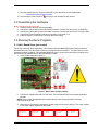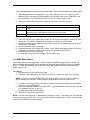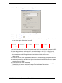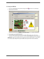
1
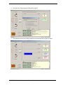
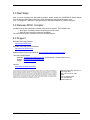
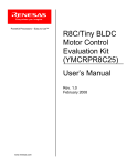
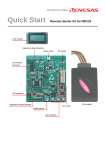
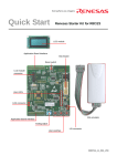
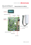
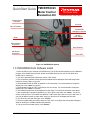
QuickStart Guide YMCRPR8C25
Motor Control
Evaluation Kit
Powerful Processors – Easy to Use™
Isolated Serial
Connector
Line cord
2x8 LCD Module
Isolated E8A
Debugger Connector
24 VDC
Power Supply
Motor
Motor Winding
Connection
User Switches
Hall Sensor
Connection
Power LED
Figure 1.0 YMCRPR8C25 System
1.0 YMCRPR8C25 Kit Software Install
1. Insert the CD into your computer’s CD-ROM drive. The CD should automatically run the installation
program. If the installer does not start, browse to the RSK directory from the CD root folder and
double click on ‘setup.exe’.
2. You will be presented with a Welcome screen, Click <Next>.
3. Two consecutive software license agreement windows will be displayed. Read and accept each
license by clicking <Yes> to continue.
4. The destination folder for HEW is specified on the next screen. It is recommended to accept the
default path. Click <Next> to continue.
5. The destination folder for FDT is specified on the next screen. It is recommended to accept the
default path. Click <Next> to continue.
6. The selected components will be displayed on this dialog. To confirm the selections click <Next>.
7. After completing the compiler installation, you will be given a site code, click <Next>. You do not
need to save this code. The installer has added an “Add License Key” short cut to your start menu. If
you wish to add the license at a later date, clicking on this short cut will display the site code.
8. You will receive the final dialog box. Click <Finish>.
9. The Auto-update dialog box will be launched. Click <OK> to configure the Auto-update settings to
allow for checking for available updates automatically.
10. On the next Auto-update screen, click <Cancel>.
YMCRPR8C25 Quick Start Guide, rev. 1.1 Page 1 of 9
11. Copy the Utilities Directory from the Install CD to your hard drive. Recommended path:
C:\Workspace\YMCRPR8C25\Utilites
12. Add a shortcut to the LEM GUI
(lem.exe) to your desktop for easy access.
2.0 Assembling the Hardware
Note:
1.
2.
3.
4.
5.
Handle all kit parts with care.
Carefully remove all parts from the packaging.
Connect the 4-wire cable to the motors white connector. Connect the other end to J2 (MOTOR).
Connect the 5-wire cable to the motors black connector. Connect the other end to J3 (HALL SEN).
Connect the Power Supplies round barrel connector to connector J1A.
Insert the “figure 8” end of the line cord into the power supply.
3.0 Running the Demo Programs
3.1. HALL Based Demo (pre-loaded)
The kit ships with two demo applications, HALL based 6-step and Back-EMF based 6-step as well as a
Windows based UI. The HALL based 6-step is pre-programmed into the MCU. The demo will run on the
board when power is applied. The application allows the user to control the motor with the program using
the switches and potentiometer on the YMCRPR8C25 board.
1. Verify Jumper settings per figure 1.
Figure 1: HALL Demo Jumper settings
2. Connect the supplied line cord to a wall outlet .The Hall based 6-step motor control Application
will start.
NOTE: Power should be applied and removed at the line cord, leaving the barrel connector
connected to the board.
3. Observe the LCD sequence through the splash screens for the demo start-up. The motor is ready
to run when display reaches the last screen.
Renesas
Technlgy
YMCRPR8C
6-Step
HALL
APPL
YMCRPR8C25 Quick Start Guide, rev. 1.1 Page 2 of 9
Carrier
12kHz
C: nnnn
M: 0000
Note: nnnn depends on the setting of the potentiometer, which sets the desired motor speed in RPM.
4. Adjust the potentiometer and watch the C: nnnn value change on the LCD. It will go from the
Minimum RPM to the Maximum RPM available in the Hall demo code (500 to 3500 RPM). Dial
the potentiometer until LCD reads the speed at which you wish the motor to start.
5. The three switches SW1 through SW3 control the motor demo as shown in table 2.
Switch
SW1
SW2
SW3
Function
Rotate CCW as you face the motor shaft (indicated as negative direction on
LCD).
STOP. MAY BE PRESSED AT ANY TIME TO STOP MOTOR when GUI is
not being used. Use E-Stop on GUI when GUI is being used.
Rotate CW as you face the motor shaft.
Table 2: Switch Function
6. Press SW1 and the motor should start to rotate. The M: display will display the speed in RPM as
measured by the software. RPM should be negative to indicate the CCW direction.
7. Rotate the potentiometer and the motor speed should track the commanded speed as set by the
potentiometer, ±100 RPM.
8. Press SW2 and the motor should stop.
9. Press SW3 and the motor should start to rotate. The M: display will display the speed in RPM as
measured by the software. RPM should be positive to indicate the CW direction.
10. Press SW2 and the motor should stop.
11. To restart the firmware, press and release the reset switch only.
3.2. BEMF Based Demo
The kit ships with two demo applications. The HALL based 6-step demo was pre-loaded. We will use
HEW to build and load the BEMF demo application the Windows based LEM GUI to help run the BEMF
Demo. The LEM GUI allows the user to control the motor with a serial interface and the E8A utilizing
HEW Target Server.
3.2.1 Set-up
1. Disconnect the line cord from the wall outlet.
2. Connect the E8A USB cable to any USB port on your PC. Connect the other end to the E8A.
NOTE: If you have not connected the E8A to your computer prior to this you will get the USB new
device message from Windows. Follow prompts to allow Windows to find the correct driver.
3. Connect the E8A Target cable (14-pin ribbon) to the E8A. Connect the other end to the DEBUG
connector on the YMCRPR8C25.
4. Connect the DB9 serial cable to J4 (COM PORT) of the YMCRPR8C25 board and the other end
to an available com port on your PC.
5. Set the jumpers as shown in FIGURE 5.
6. Reconnect the line cord to a wall outlet.
NOTE: The LEM GUI used by the YMCRPR8C25 defaults to COM1. This setting may be edited the
lem.ini file used by the LEM GUI. For this and other COM port related issues, see the troubleshooting
section of the YMCRPR8C25 User’s Manual.
YMCRPR8C25 Quick Start Guide, rev. 1.1 Page 3 of 9
3.3. Building BEMF Application using HEW IDE
The High-performance Embedded Workshop software (HEW) integrates various tools such as the
compiler, assembler, debugger, and editor into a common Graphical User Interface.
1. Launch HEW from the Start menu (Start > (All)
Programs > Renesas > High-performance
Embedded Workshop > High-performance
Embedded Workshop).
2. In the “Welcome!” dialog box:.
i.) Verify that “Create a new project
workspace” is selected.
ii.) Click <OK>.
3. In the “New Project Workspace” dialog box:
i.) Verify that “CPU family” is set to “M16C”
and “Tool chain” is set to “Renesas
M16C Standard”.
ii.) Select “YMCRPR8C25” for Project Type.
iii.) Enter “BEMF_APP” for the Workspace.
The Project Name will auto fill with the
Workspace name.
iv.) Click <OK>.
4. In the “YMCRPR8C25 Kit – Step 1” window:
i.) Select “Motor Application”.
ii.) Click <Next>.
5. In the “YMCRPR8C25 Kit – Step 2” window:
i.) Select “BEMF_APP”
ii.) Click <Next>.
6. In the “YMCRPR8C25 Kit – Step 3” window:
Click <Finish>.
7. In the “Project generator information” window:
Click <OK>. The project that is created has two
configurations: The “Release” configuration can
be used for the final release code version and
by default, the executable does not include
debug information. The “Debug” configuration
allows full source level debugging within HEW.
8. Select the “Debug” build configuration in the left
hand drop down list on the tool bar.
(Figure 2)
Figure 1: HEW New Project Workspace
Figure 2: Debug Configuration
9. Click the “Build” icon
to compile, assemble and
link the project. After the build is complete, the
HEW Build window will look similar to Figure 3.
Figure 3: HEW Build Complete
NOTE: The BEMF application should default to the correct session which is the SessionR8C_E8a. If
it does not, use pull-down to select correct session.
10. Connect to the YMCRPR8C25 by clicking connect icon
YMCRPR8C25 Quick Start Guide, rev. 1.1 Page 4 of 9
.
11. Select Emulator dialog options as shown in figure 4.
Figure 4: Emulator Setting
12. Select [menu] Debug>>Download>>All Download Modules
13. Select [menu] Debug>>
Reset Go
14. Observe the LCD sequence through the splash screens for the demo start-up. The motor is ready
to run when display reaches the last screen.
Renesas
Technlgy
YMCRPR8C
6-Step
Back-EMF
APPL
Carrier
12kHz
C: nnnn
M: 0000
Note: nnnn depends on the setting of the potentiometer, which sets the desired motor speed in RPM.
15. Adjust the potentiometer and watch the C: nnnn value change on the LCD. It will go from the
Minimum RPM to the Maximum RPM available in the Hall demo code (500 to 3000 RPM). Dial
the potentiometer until LCD reads the speed at which you wish the motor to start.
16. The three switches SW1 through SW3 control the motor demo as shown in table 2 in the HALL
demo section.
17. Press SW1 and the motor should start to rotate. The M: display will display the speed in RPM as
measured by the software. RPM should be negative to indicate the CCW direction.
18. Rotate the potentiometer and the motor speed should track the commanded speed as set by the
potentiometer, ±100 RPM.
19. Press SW2 and the motor should stop.
20. Press SW3 and the motor should start to rotate. The M: display will display the speed in RPM as
measured by the software. RPM should be positive to indicate the CW direction.
21. Press SW2 and the motor should stop.
YMCRPR8C25 Quick Start Guide, rev. 1.1 Page 5 of 9
3.4. Using the LEM GUI
1. Launch the YMCRPR8C25 GUI by double-clicking the LEM
2. Observe screen as follows:
Shortcut Icon on the desktop.
FIGURE 5: GUI Interface Screen
3. Select program type “BackEMF Algorithm”.
4. Check the jumper settings and precautions for the Back EMF algorithm per the GUI screen
instructions. The jumper settings may also be verified using Error! Reference source not found..
IMPORTANT: Neither motor algorithm will run properly with incorrect jumper settings. If motor fails to
run, re-check jumper settings for the proper feedback chosen (also found in the User’s Manual).
YMCRPR8C25 Quick Start Guide, rev. 1.1 Page 6 of 9
5. Click OK to the Target Operation Dialog Box as shown
6. The LEM GUI will connect to HEW, initialize the board and start the program as shown
YMCRPR8C25 Quick Start Guide, rev. 1.1 Page 7 of 9
7. Observe the LCD sequence through the splash screens for the demo start-up. The motor is ready
to run when display reaches the last screen.
Renesas
Technlgy
YMCRPR8C
6-Step
Back-EMF
APPL
Carrier
12kHz
C: nnnn
M: 0000
Note: nnnn depends on the setting of the potentiometer, which set the desired motor speed in RPM
however, once the GUI takes control the potentiometer setting and switches are ignored. The LCD
will indicate the slider setting on the GUI as indication of the commanded RPM
8. Select any speed greater than minimum to start the motor spinning in that direction.
9. Adjust the “slider” and watch the C: nnnn value change on the LCD. It will go from the Minimum
RPM to the Maximum RPM available in the BEMF demo code (500 to 3000 RPM). Move the
slider to the desired speed in RPM.
10. Press the Stop icon
next to the slider to decelerate the motor to a stop, or the “Emergency
to stop the motor immediately.
Stop” button
11. Pressing the reset switch on the board will also stop the motor, but will cause the LEM GUI
communication to stop. Exit LEM, restart the debugger with Debug>>
restarting the LEM GUI.
Reset Go before
NOTE: The BEMF demo will operate in the same manner as the HALL Demo using SW1, SW2, and
SW3 as noted in section 3.1, table 2 when the GUI is not open and in control of the demo.
YMCRPR8C25 Quick Start Guide, rev. 1.1 Page 8 of 9
4.0 Next Steps
After you have completed this QuickStart procedure, please review the YMCRPR8C25 User’s Manual.
You can find the User’s Manual and other useful documents in the Manual Navigator, click:
Start > All Programs > Renesas > High-performance Embedded Workshop > Manual Navigator.
5.0 Renesas M16C Compiler
Included in the kit is the Evaluation Version of the M16C C-compiler. The limitations are:
1. No support or warranty without the purchase of a full license.
2. After 60 days, code size is limited to 64 KBytes.
The full licensed version is available from your Renesas supplier.
6.0 Support
Renesas Technology Website
http://www.renesas.com/
Renesas Technology America Website
http://america.renesas.com/
Additional Motor Control information at: http://america.renesas.com/motorcontrol
Technical Contact Details:
America: [email protected] (United States / Canada / Mexico only )
Europe: [email protected]
Global: [email protected]
Inquiries
http://www.renesas.com/inquiry
© 2007 Renesas Technology America, Inc. Renesas Technology America, Inc. is a wholly owned subsidiary of
Renesas Technology Corporation. All trademarks are the property of their respective owners. The information
supplied by Renesas Technology America, Inc. is believed to be accurate and reliable, but in no event shall
Renesas Technology America, Inc. be liable for any damages whatsoever arising out of the use or inability to
use the information or any errors that may appear in this publication. The information is provided as is without
any warranties of any kind, either express or implied. Renesas Technology America, Inc. reserves the right,
without notice, to make changes to the information or to the design and specifications of its hardware and/or
software products. Products subject to availability. Printed in U.S.A.
YMCRPR8C25 Quick Start Guide, rev. 1.1 Page 9 of 9
Renesas Technology America, Inc.
450 Holger Way
San Jose, CA 95134-1368
USA
Phone: 408-382-7500
Fax: 408-382-7501
www.renesas.com