1
To our customers,
Old Company Name in Catalogs and Other Documents
On April 1st, 2010, NEC Electronics Corporation merged with Renesas Technology
Corporation, and Renesas Electronics Corporation took over all the business of both
companies. Therefore, although the old company name remains in this document, it is a valid
Renesas Electronics document. We appreciate your understanding.
Renesas Electronics website: http://www.renesas.com
April 1st, 2010
Renesas Electronics Corporation
Issued by: Renesas Electronics Corporation (http://www.renesas.com)
Send any inquiries to http://www.renesas.com/inquiry.
Notice
1.
2.
3.
4.
5.
6.
7.
All information included in this document is current as of the date this document is issued. Such information, however, is
subject to change without any prior notice. Before purchasing or using any Renesas Electronics products listed herein, please
confirm the latest product information with a Renesas Electronics sales office. Also, please pay regular and careful attention to
additional and different information to be disclosed by Renesas Electronics such as that disclosed through our website.
Renesas Electronics does not assume any liability for infringement of patents, copyrights, or other intellectual property rights
of third parties by or arising from the use of Renesas Electronics products or technical information described in this document.
No license, express, implied or otherwise, is granted hereby under any patents, copyrights or other intellectual property rights
of Renesas Electronics or others.
You should not alter, modify, copy, or otherwise misappropriate any Renesas Electronics product, whether in whole or in part.
Descriptions of circuits, software and other related information in this document are provided only to illustrate the operation of
semiconductor products and application examples. You are fully responsible for the incorporation of these circuits, software,
and information in the design of your equipment. Renesas Electronics assumes no responsibility for any losses incurred by
you or third parties arising from the use of these circuits, software, or information.
When exporting the products or technology described in this document, you should comply with the applicable export control
laws and regulations and follow the procedures required by such laws and regulations. You should not use Renesas
Electronics products or the technology described in this document for any purpose relating to military applications or use by
the military, including but not limited to the development of weapons of mass destruction. Renesas Electronics products and
technology may not be used for or incorporated into any products or systems whose manufacture, use, or sale is prohibited
under any applicable domestic or foreign laws or regulations.
Renesas Electronics has used reasonable care in preparing the information included in this document, but Renesas Electronics
does not warrant that such information is error free. Renesas Electronics assumes no liability whatsoever for any damages
incurred by you resulting from errors in or omissions from the information included herein.
Renesas Electronics products are classified according to the following three quality grades: “Standard”, “High Quality”, and
“Specific”. The recommended applications for each Renesas Electronics product depends on the product’s quality grade, as
indicated below. You must check the quality grade of each Renesas Electronics product before using it in a particular
application. You may not use any Renesas Electronics product for any application categorized as “Specific” without the prior
written consent of Renesas Electronics. Further, you may not use any Renesas Electronics product for any application for
which it is not intended without the prior written consent of Renesas Electronics. Renesas Electronics shall not be in any way
liable for any damages or losses incurred by you or third parties arising from the use of any Renesas Electronics product for an
application categorized as “Specific” or for which the product is not intended where you have failed to obtain the prior written
consent of Renesas Electronics. The quality grade of each Renesas Electronics product is “Standard” unless otherwise
expressly specified in a Renesas Electronics data sheets or data books, etc.
“Standard”:
8.
9.
10.
11.
12.
Computers; office equipment; communications equipment; test and measurement equipment; audio and visual
equipment; home electronic appliances; machine tools; personal electronic equipment; and industrial robots.
“High Quality”: Transportation equipment (automobiles, trains, ships, etc.); traffic control systems; anti-disaster systems; anticrime systems; safety equipment; and medical equipment not specifically designed for life support.
“Specific”:
Aircraft; aerospace equipment; submersible repeaters; nuclear reactor control systems; medical equipment or
systems for life support (e.g. artificial life support devices or systems), surgical implantations, or healthcare
intervention (e.g. excision, etc.), and any other applications or purposes that pose a direct threat to human life.
You should use the Renesas Electronics products described in this document within the range specified by Renesas Electronics,
especially with respect to the maximum rating, operating supply voltage range, movement power voltage range, heat radiation
characteristics, installation and other product characteristics. Renesas Electronics shall have no liability for malfunctions or
damages arising out of the use of Renesas Electronics products beyond such specified ranges.
Although Renesas Electronics endeavors to improve the quality and reliability of its products, semiconductor products have
specific characteristics such as the occurrence of failure at a certain rate and malfunctions under certain use conditions. Further,
Renesas Electronics products are not subject to radiation resistance design. Please be sure to implement safety measures to
guard them against the possibility of physical injury, and injury or damage caused by fire in the event of the failure of a
Renesas Electronics product, such as safety design for hardware and software including but not limited to redundancy, fire
control and malfunction prevention, appropriate treatment for aging degradation or any other appropriate measures. Because
the evaluation of microcomputer software alone is very difficult, please evaluate the safety of the final products or system
manufactured by you.
Please contact a Renesas Electronics sales office for details as to environmental matters such as the environmental
compatibility of each Renesas Electronics product. Please use Renesas Electronics products in compliance with all applicable
laws and regulations that regulate the inclusion or use of controlled substances, including without limitation, the EU RoHS
Directive. Renesas Electronics assumes no liability for damages or losses occurring as a result of your noncompliance with
applicable laws and regulations.
This document may not be reproduced or duplicated, in any form, in whole or in part, without prior written consent of Renesas
Electronics.
Please contact a Renesas Electronics sales office if you have any questions regarding the information contained in this
document or Renesas Electronics products, or if you have any other inquiries.
(Note 1) “Renesas Electronics” as used in this document means Renesas Electronics Corporation and also includes its majorityowned subsidiaries.
(Note 2) “Renesas Electronics product(s)” means any product developed or manufactured by or for Renesas Electronics.
APPLICATION NOTE
R8C/25 Group
Driving of a 3-phase BLDC Motor by 120-Degree Trapezoidal Wave
Commutation using HALL Sensors
Table of Contents:
1.0 Abstract ............................................................................................................................................. 2
2.0 Conditions ......................................................................................................................................... 2
3.0 Introduction........................................................................................................................................ 2
3.1. Basic 3-phase Inverter Topology. ..................................................................................................... 2
3.1.1.
General Inverter Topology....................................................................................................... 2
3.1.2.
R8C/25 Specific Inverter Topology.......................................................................................... 3
3.2. Basics of Trapezoidal Commutation (6-step).................................................................................... 3
3.2.1.
Controlling Phase Voltage ....................................................................................................... 3
3.2.2.
Rotor Position .......................................................................................................................... 4
3.2.3.
Commutating ........................................................................................................................... 5
3.3. Measuring Speed .............................................................................................................................. 5
3.4. Basics of PI Speed Loop................................................................................................................... 6
3.5. Implementation and Testing.............................................................................................................. 8
3.5.1.
The 6-step state machine and Commutation .......................................................................... 8
3.5.2.
Hall Signature Testing ........................................................................................................... 10
3.5.3.
Motor Testing......................................................................................................................... 11
4.0 Reference........................................................................................................................................ 12
5.0 Programming Code ......................................................................................................................... 12
6.0 Glossary .......................................................................................................................................... 12
6.1. Acronyms ........................................................................................................................................ 12
REU05B0074-0101/Rev.1.01
December 2008
Page 1 of 14
R8C/25 Group
Six-Step Trapezoidal Control using HALL Sensors
1.0 Abstract
This Application Note shows the implementation of 3-phase BLDC motor drive by 120-degree trapezoidal wave
commutation. The method shown utilizes the HALL sensors in the motor to determine the motors rotor position, effect
commutation, and provide speed measurement.
This example applies to MCUs in the R8C/24 Group.
2.0 Conditions
The explanation of this issue is applied to the following condition:
Applicable MCU: R8C/24 Group (such as R8C/25 device R5F21256)
MCU operational frequency: 20 MHz
Memory size: ROM 32 KB, RAM 1 KB
Peripherals: Timer RD for PWM motor drive, Timer RB for speed measurement
3.0 Introduction
The R8C Family has a number of peripherals suitable for motor inverter drive applications. In this application
note we will take a look at the R8C/24 Group, specifically the R8C/25 driving a 3-phase BLDC motor using
the 120° trapezoidal method, also referred to as 6-step. The 6-step method is one of the simplest method for
driving 3-phase BLDC motors and in the past was done using discrete logic gates, but with the more
powerful peripherals available in today’s microcontrollers, such as the R8C Family, we can provide more
functionality, better energy usage, and higher safety level when driving motors.
In this application note we will show: 6-step commutation using HALL Sensors, speed measurement using
TimerRB, Current measurement using A/D and a basic Proportional-Integral (PI) Speed loop.
This application note is intended to be a primer in 6-step commutation and using the R8C peripherals to drive
a three phase BLDC motor. It is not intended to provide in-depth theoretical motor training.
3.1. Basic 3-phase Inverter Topology.
3.1.1. General Inverter Topology
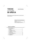
Figure 3.1 shows the basic Inverter topology for driving 3-phase motors. In the case of this
application note, the control electronics would be the R8C/25. It is important to note that it requires 6
outputs to drive the inverter section. Timer RD in the R8C family is perfectly suited for this task, and
supports “dead-time” to prevent “shoot-through” current on the IGBTs.
Figure 3.1: Basic Converter/Inverter Connections
REU05B0074-0101/Rev.1.01
December 2008
Page 2 of 14
R8C/25 Group
Six-Step Trapezoidal Control using HALL Sensors
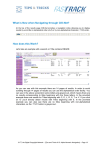
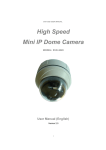
3.1.2. R8C/25 Specific Inverter Topology
Figure 3.2 shows the specific architecture of the YMCRPR8C25 Demo board used to develop this
Application Note. Note the additional functions over the basic inverter motor drive topology. We can
use A/D channels to monitor the Bus voltage for “droop”, motor current for excessive current or to
implement “torque control”. We can use the R8C timer set to measure speed and implement a
speed control loop rather than just the simple open-loop control.
R8C/25
Inverter
U
U
V
V
W
W
Timer RD
Phase
Current
Vbus
Monitor
output
ADC
ADC
ADC
P45/INT0
Shunt Current
M
output buffer cut off input
(Over current)
SCI
Timer RB
SCI
I
N
T
Hall Signals
To host
Figure 3.2: Block Diagram, R8C/25 Motor Control
3.2. Basics of Trapezoidal Commutation (6-step).
The 6-step method is one of the simplest methods for driving 3-phase BLDC motors. It is also know as
120-Degree trapezoidal, since it drives each winding for 120-degrees of the electrical rotation and leaves
the winding un-driven for 60 degrees. Note, although the drive method is simple, this lack of drive for 60
degrees also results in higher torque ripple in the end application. The system designer must decide if
this is acceptable or other drive methods should be considered.
3.2.1. Controlling Phase Voltage
The basic voltage control for the three windings of the motor is performed using Phase-Width
Modulation (PWM). In section 3.1 we showed how we will connect the microcontroller to the power
inverter stage to control the gates of the IGBTs. In effect, the PWM duty cycle controls the voltage
at the motors terminal. There are various modulation methods used in today’s inverter drives.
Typically modulation techiques are Upper modulation, Lower Modulation, rotating Modulation, or
Balanced Modulation. For this application note we will be showing Upper modulation only. Figure
3.3 shows the basic upper modulation waveforms. Note that in this method, only the “P” or upper
IGBTs are modulated.
REU05B0074-0101/Rev.1.01
December 2008
Page 3 of 14
R8C/25 Group
Six-Step Trapezoidal Control using HALL Sensors
STEP1
STEP2
STEP3
STEP4
STEP5
STEP6
STEP1
STEP2
STEP3
STEP4
STEP5
STEP6
STEP1
H1
H2
H3
UP
UN
VP
VN
WP
WN
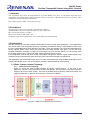
FIGURE 3.3: Upper Modulation (Active-low Drive)
NOTE: Timer RD in the R8C Family can do any of the modulation techniques and is not limited to
single-sided modulation techniques. This would include sinusoidal modulation for other motor types
such as 3-phase induction.
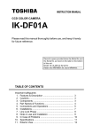
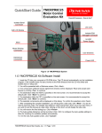
3.2.2. Rotor Position
Now we have control over the voltage on the windings (and indirectly the current) through the use of
a PWM timer, but we must present these signals in the appropriate sequence to properly commutate
the motor. In order to do this we must know the rotor position. We will do this with the Hall sensors
which sense the position of the rotor. They can do this because they are positioned relative to each
motor phase winding in the stator coils (see figure Figure 3.). Figure 3.5 shows a typical HALL cell
signature. Note that the state changes every 60° for one electrical cycle. We can then read these on
GPIO pins of the R8C and decode them into a 60° rotor position. The number of electrical cycles in
one mechanical rotation is based on the number of “pole-pairs” (magnetic poles) in the motor. For
the figure given this is 1 pole pair, the motor in the YMCRPR8C25 demo kit has 5 pole-pairs.
N2
60°
N
0°
H2
S
H1
N1
S
H1, H2 and H3 are Hall IC
Figure 3.4: Hall Mounting
REU05B0074-0101/Rev.1.01
N1
Hall IC Signals
θ
H3
S
N2
0
60 120 180 240 300 360
Figure 3.5: Typical HALL Signature
December 2008
Page 4 of 14
R8C/25 Group
Six-Step Trapezoidal Control using HALL Sensors
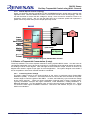
3.2.3. Commutating
So now we can control the voltage, we know where the rotor is so let’s put them together.
A motor manufacturer’s data sheet will typically tell you “…when you see this HALL signature, drive
these phase windings”. Figure 3.6 shows a typical commutation sequence. For this motor, when
we see the HALL signature for STEP1, we drive UP and VN. The rotor will move because the torque
being caused by the magnetic fields in the stator coils are being applied at the correct angle to the
magnets on the rotor and they will attempt to align. When we see the Hall signature change state to
indicate Step 2 we switch the drive from UP and VN to UP and WN, and the rotor will continue to move.
This will continue for the entire cycle until we are back at Step one and the process repeats. This is
how we commutate the motor; the speed it rotates at is a function of the motor current which we set
by controlling the phase voltage as outlined in section 3.2.1.
= Transistor Active
Step
1
step
2
step
3
step
4
step
5
step
6
Up
Un
Up
Un
Up
Un
Up
Un
Up
Un
Up
Un
Vp
Vn
Vp
Vn
Vp
Vn
Vp
Vn
Vp
Vn
Vp
Vn
Wp
Wn
Wp
Wn
Wp
Wn
Wp
Wn
Wp
Wn
Wp
Wn
Figure 3.6: Typical Commutation sequence.
3.3. Measuring Speed
There are a few basic methods for measuring the mechanical speed in a rotating motor. The simplest is
to use a tachometer attached to the rotor that outputs a given number of pulses for a single rotation. In
essence, we will use the Hall Sensors as a tachometer of sorts. Although not attached to the rotor, they
do give a fixed number of pulses for a single rotation (i.e. a direct relationship to rotor speed). We will
feed the Hall sensors into an interrupt pin of the R8C and detect both edges to double the number of
“speed measurements” in a given rotation. This number will be: Number of Hall sensors * number of
edges * the number of pole pairs in the motor = measurement points. For the demo motor which has 5
poles, this will be: 3 * 2 * 5 = 30 measurements per rotation. If we measure the time between each
interrupt using a fixed processor clock and timer, we can then derive the speed.
Speed = clock period * number of counts.
We have in effect created an input capture timer using three inputs.
The code uses Timer RB as a 16 bit down counter. It does this by reading both the pre-scaler and the
Timer RB register during the interrupt service routine. The 16 bits are kept coherent by stopping the
timer to prevent a pre-scaler underflow in between the read of the pre-scaler and the read of the timer.
The value is assembled in a structure accessible as 2 BYTEs or a WORD. The timer and pre-scaler are
then reloaded with the normal reload value (0xFF and 0xFF).
Since the upper level code that converts counts to RPM uses positive numbers, the value is inverted by
subtracting it from the timer RB starting count of 65,535 (0xffff) and this value is returned.
REU05B0074-0101/Rev.1.01
December 2008
Page 5 of 14
R8C/25 Group
Six-Step Trapezoidal Control using HALL Sensors
In applications that may require very high accuracy, the return value may be adjusted by the number of
counts required to stop, read and re-start Timer RB. This value may be derived empirically or
determined by evaluating the code using the cycle accurate simulator in the tool chain.
So let’s look at an example:
Assume we are using a 2.5MHz clock for timer RB, and we get a count of 2500.
2500 counts / 2.5M counts/second = 1 millisecond.
Since this represents 60 electrical degrees or 1/30 of a revolution we can then calculate out:
30 * 1mS = 30mS per revolution or 33.33 Revs per second * 60 seconds/minute = 2000 RPM
In addition to measuring speed, the Timer RB underflow can be used to detect slow or stalled motor.
NOTE: Due to asymmetry in the output of the Hall sensors, it is highly recommended that speed
measurements be averaged or filtered. Since the speed loop is typically running at some lower rate than
the PWM, this is (typically) not a problem. In addition, if the averaging is a power of 2 (2, 4, 8, etc…) the
averaging then becomes just a shift which is easily performed by the R8C.
3.4. Basics of PI Speed Loop
So now we can commutate to move the motor, measure its speed, and vary the phase voltage to control
its speed, how do we keep the speed accurate under varying loads? For this we will incorporate a basic
PI speed loop, a feedback system (quick run, Control Systems 101 rears its ugly head). Figure 3.7
shows our basic PI speed loop.
Speed Loop
vu,vv,vW
Speed command
+
ωr*
-
Voltage to
PWM Count
Conversion
ASR
PWM
H-Bridge
3
(Timer RD)
GPIO**
M
3
ωr
Counter
(Timer RB)
Rotating speed ωr
Micro Computer
ASR - Auto Speed Regulator - PI Controller
Hall Sensor
(position* / tach)
* Although it is actually telling us position, we only use that information for commutation
** Not part of control loop, but shown for clarity
ωr*
ωr
- Commanded speed in Radians per second
- Measured speed in Radians per second
Figure 3.7: Basic PI Speed loop
Remember from your basic control systems, a typical loop consists of:
a) feedback element, in this case the Hall sensor and timer RB feeding back speed,
b) error detection, typically summing junction, in this case single line of code that compares
commanded speed against measured speed to calculate error
c) Gain stage (amplifier), in this case software that scales the error by gain and computes voltage
required to correct the speed.
Very similar to controls you see in hardware.
One important point to note, we can control the voltage of the motor through PWM. Since torque in a
motor is related to current and not voltage, the output of the ASR calculations is a current reference for
the given error. We will need some calculations to convert current to voltage.
REU05B0074-0101/Rev.1.01
December 2008
Page 6 of 14
R8C/25 Group
Six-Step Trapezoidal Control using HALL Sensors
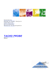
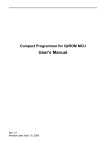
So a quick review of Proportional Gain and Integral Gain is in order now.
The most basic type of control loop is Proportional, where the correction provided is simply a factor of
how much difference there is between the commanded and actual values. The more error, the more
correction. This type is usually stable, but allows some error to exist, so it is not good for highest
accuracy.
Sp eed
Step Response
120
100
80
60
40
20
0
-20
1
10 19 28 37 46 55 64 73 82 91 100 109 118 127 136 145 154 163 172 181 190 199
Time
Figure 3.8: Loop Response P-Gain Only
By using an integrator in the loop, (adding the accumulated error over time), we can eliminate long
term error that the Proportional loop allowed. This improves the basic accuracy. But, these systems
can also become unstable and oscillate around the set point. Some damping in the system, like friction
or resistance, does reduce the tendency to oscillate.
Speed
Step Response
120
100
80
60
40
20
0
-20
1
10 19 28 37 46 55 64 73 82 91 100 109 118 127 136 145 154 163 172 181 190 199
Time
Figure 3.8: Loop Response P-Gain and I-Gain
So now back to our implementation.
So the pseudo-code would look like this:
Error = ωr* - ωr;
// calculate the speed error
Current_Reference = P-Gain * Error;
// calculate our current reference
Current_Reference = Current_Reference + Current_Integral; // add in the integral
Current_Integral = Current_Integral + (Error * I-Gain);
// accumulate the error as Integral
The key to this implementation is the fact that the speed loop corrections are applied synchronously to
the PWM frequency at some fixed rate that is a sub-frequency of the carrier. So although the speed
measurements are asynchronous in nature (i.e. we don’t know when a Hall interrupt will come in), we
apply the correction at a give frequency.
Also an important point to remember, there are multiple ways to implement these control loops. The way
we show it here is very simple in software, but it does require the Integral portion for the loop to converge
on the correct speed. If integral gain is set to 0, this loop will tend to “bang” back and forth trying to
correct the speed, but never actually hitting the correct speed. How fast it does this is based on the
having the correct P-Gain and I-Gain in the software (too in-depth to explore in this application note).
REU05B0074-0101/Rev.1.01
December 2008
Page 7 of 14
R8C/25 Group
Six-Step Trapezoidal Control using HALL Sensors
So now we have a current reference representing how we should drive the motor, so we need to get that
into the correct “domain” so we can drive the motor with voltage. This means we need to go from
Current to Volts (Ohm’s law) to get an absolute motor voltage. After this we need to bring that into our
Bus Voltage domain (for example we might need 12V on the motor and we have 24V on the Bus).
Finally, the ratio is converted to an absolute count for the PWM timer. This transition is shown in a few
lines of pseudo-code below.
Voltage_PWM = Current_Reference * Motor_Impedance; // Current to Absolute Motor Voltage
Counts = Voltage_PWM * VBus_Inverse;
// ratio of Motor Voltage to Bus Voltage
PWM_Counts = Counts * PWM_MAX;
// finally actual PWM counts to load in timer
The reader should download the source code as listed in section 5 for complete details and actual code
implementation.
NOTE: This sample project for driving BLDC motors is not optimized, rather it is written for clarity an
example purposes. Many of the calculations can be rolled into a single calculation. For example a
single multiply in the speed loop can encompass both the P-Gain and the Motor Impedance so you get a
number back from the speed control function that can be converted to PWM counts directly.
3.5. Implementation and Testing
So now that we’ve given you a basic overview, let’s discuss the quick testing method we did and some
insight into how this was implemented in software.
3.5.1. The 6-step state machine and Commutation
So we first had to implement a simple finite state machine so we could commutate the motor and
know which windings to drive. We chose to do simple enumerations of the steps and start the
numbering at 0 so we can use STEP1 though STEP6 as look-up variable into tables. Since we were
making this portable we included some steps (underflow and align) required for “open-loop
operation”, but that is for another app note. For now, we can just understand we will use STEP1
through STEP6 (NO_STEP is used to force no commutation/drive in open-loop).
SO you can see from the code piece in Figure 3.10, we have
defined the steps in such a manner as to provide a direction
look-up into the drive tables (i.e. STEP1 through STEP6
equal 0 through 5 respectively). In addition, we have defined
an Underflow value to detect when our open-loop
commutation should move from STEP1 to STEP6.
Now that these values are set up in this manner we can use
them to directly look-up the proper pins to drive in the look-up
table. See figure 3.11.
typedef enum {
STEP_UNDERFLOW = -1,
STEP1,
STEP2,
STEP3,
STEP4,
STEP5,
STEP6,
ALIGN_STEP,
NO_STEP
} STEP_STATE;
FIGURE 3.10: STEP Enumerations
REU05B0074-0101/Rev.1.01
December 2008
Page 8 of 14
R8C/25 Group
Six-Step Trapezoidal Control using HALL Sensors
#pragma rom low_side_step_table
const UI08 low_side_step_table[8] = {
VN_ON, // Step 1
WN_ON, // Step 2
WN_ON, // Step 3
UN_ON, // Step 4
UN_ON, // Step 5
VN_ON, // Step 6
ALIGN_MASK,
// Align
0
// NO Step
};
#pragma rom high_side_step_table
const UI08 high_side_step_table[8] = {
UP_ON, // Step 1, Up Active (modulated)
UP_ON, // Step 2, Up Active (modulated)
VP_ON, // Step 3, Vp Active (modulated)
VP_ON, // Step 4, Vp Active (modulated)
WP_ON, // Step 5, Wp Active (modulated)
WP_ON, // Step 6, Wp Active (modulated)
UP_ON, // Align, Up Active (modulated)
0
// NO Step
};
FIGURE 3.11: Pin Drive Look-up tables
So you can see when using these tables, if when we see STEP1 on the HALL Cells, we will drive
UP_ON on the high-side and VN_ON on the low-side. All we need to do is construct these tables
properly for a given motor and connections and it will commutate properly.
STEP1
STEP6
STEP5
STEP4
STEP3
STEP2
STEP1
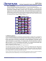
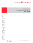
In order to test these, we do not hook them up to the motor or power stage (bad things happen when
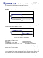
motor software has bugs). Rather we hook a signal generator into one of the Hall inputs on the
microcontroller to simulate a spinning motor. We then look at our “commutation” using scopes and
analyzers. Figure 3.12 shows the actual PWM signals from the processor during our 6-step
commutation.
Figure 3.12: Logic analyzer capture of 6-step PWM signals (Active-low).
NOTE: STEP1 signal is I/O port set in software to signal state is STEP1
So looking at these signals, we have a pretty good idea that our motor will spin if driven by this code,
assuming our Hall Sensor Signature (look-up table) is correct.
REU05B0074-0101/Rev.1.01
December 2008
Page 9 of 14
R8C/25 Group
Six-Step Trapezoidal Control using HALL Sensors
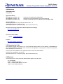
3.5.2. Hall Signature Testing
So we still do not need to hook up the motor windings. To reiterate, bad things happen when motor
software has bugs! We just hook up the Hall sensor to our inputs and capture the Hall signals with a
scope and the software.
U Phase Current
Hall A
Hall B
Hall C
Figure 3.13: Hall Sensor signature and Phase Current
You can see from this figure that the HALL pattern is not directly correlated to a STEP number;
however, the software needs to know where the rotor is. For this we construct a revesre look-up
table that translates
#pragma rom HallTable[]
const HALL_TBL_ENTRY HallTable[] = {
NO_STEP,0,
// 0 = NO_STEP
STEP2, THETA_60DEG,
// 1 = STEP2
STEP4, THETA_180DEG, // 2 = STEP4
STEP3, THETA_120DEG, // 3 = STEP3
STEP6, THETA_300DEG, // 4 = STEP6
STEP1, THETA_0DEG,
// 5 = STEP1
STEP5, THETA_240DEG, // 6 = STEP5
NO_STEP,0
// 7 = NO_STEP
};
FIGURE 3.14: HALL Reverse look-up Table
NOTE: This scope picture was taken from an electrically driven motor, but the Hall signals would
look the same if you were spinning it by hand. You can observe the “un-driven” times of the phase
current. This is one thing that produces torque ripple in 6-step motor drive.
So electrically they look like we would expect, so how does our Hall look-up table function? For this
we need to capture the values in software. As our STEP machine was “commutating” from the Hall
sensors, the software tracked where it thought it was and where the Hall sensor told us it was. It
captured this in an array named test_data.
NOTE: Since we used enumerations for the steps, the watch window is able to decode and display
in basically an easy to read “English” language rather than us trying to decode a 0x05 for example.
REU05B0074-0101/Rev.1.01
December 2008
Page 10 of 14
R8C/25 Group
Six-Step Trapezoidal Control using HALL Sensors
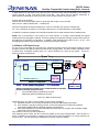
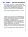
3.5.3. Motor Testing
At this point I would feel somewhat safe in hooking up my motor to my power stage and trying to run
the motor. My first attempts would probably be with fixed duty cycles on the PWM so as not to worry
about “un-tuned PI loop”, but it should run.
STEP1
STEP6
STEP5
STEP4
STEP3
STEP2
STEP1
So finally, let’s look at the Motor phase voltages of a properly commutating BLDC motor. You can
clearly see the commutation states as shown in figure 3.15. In Step1 we drive UP and VN, in Step 2
we switch the drive from UP and VN to UP and WN, and so on. As an exercise, the reader can
validate the rest of the states to confirm the drive matches the drive given in the previously given
tables.
Figure 3.15: Motor Winding on Commutating Motor
.....
REU05B0074-0101/Rev.1.01
December 2008
Page 11 of 14
R8C/25 Group
Six-Step Trapezoidal Control using HALL Sensors
4.0 Reference
YMCRPR8C25 Kit
User Manual
Application Notes
REJ05B0845-0100/Rev.1.00
REJ05B0486-0100/Rev.1.00
REU05B0073-0100/Rev.1.00
Timer RD in Complementary PWM Mode
Solutions for Three-Phase Motor Control Programming
Six Step Trapezoidal Control of a BLDC Motor Using Back EMF
Hardware Manual
R8C/24 group, R8C/25 Group Hardware Manual Rev. 1.0
YMCRPR8C25 Motor Control Demo Kit
(Use the latest version on the home page: http://www.renesas.com)
Renesas Technology Corporation Semiconductor Home Page
http://www.renesas.com/
Technical Contact Details:
Global:
[email protected]
Inquiries
http://www.renesas.com/inquiry
5.0 Programming Code
The example program was written to run on the Renesas R8C/25 Motor Control Platform (YMCRPR8C25)
but could be modified to implement motor control in a user application. The program is written in C (Renesas
M16C Standard tool chain V5.43).
Code may be downloaded from the Application Section of the Renesas Website
Filename: an_reu05b0074_r8c_apl.zip
(Use the latest version on the home page: http://www.renesas.com)
6.0 Glossary
The following terms, acronyms and/or abbreviations appear in this app note.
6.1. Acronyms
BLDC – Brushless DC Motor
IGBT – Insulated Gate Bipolar Transistor
PWM – Pulse Width Modulation
REU05B0074-0101/Rev.1.01
December 2008
Page 12 of 14
APPLICATION NOTE
Revision Record
Rev.
1.00
1.01
Date
Feb.05.08
Dec.08.08
Description
Page
Summary
—
First edition issued
14
Updated references
All trademarks and registered trademarks are the property of their respective owners.
REU05B0074-0101/Rev.1.01
December 2008
Page 13 of 14
R8C Family
Six-Step Trapezoidal Control using HALL Sensors
Notes regarding these materials
1.
2.
3.
4.
5.
6.
7.
8.
9.
10.
11.
12.
13.
This document is provided for reference purposes only so that Renesas customers may select the appropriate
Renesas products for their use. Renesas neither makes warranties or representations with respect to the
accuracy or completeness of the information contained in this document nor grants any license to any intellectual
property rights or any other rights of Renesas or any third party with respect to the information in this document.
Renesas shall have no liability for damages or infringement of any intellectual property or other rights arising out
of the use of any information in this document, including, but not limited to, product data, diagrams, charts,
programs, algorithms, and application circuit examples.
You should not use the products or the technology described in this document for the purpose of military
applications such as the development of weapons of mass destruction or for the purpose of any other military
use. When exporting the products or technology described herein, you should follow the applicable export
control laws and regulations, and procedures required by such laws and regulations.
All information included in this document such as product data, diagrams, charts, programs, algorithms, and
application circuit examples, is current as of the date this document is issued. Such information, however, is
subject to change without any prior notice. Before purchasing or using any Renesas products listed in this
document, please confirm the latest product information with a Renesas sales office. Also, please pay regular
and careful attention to additional and different information to be disclosed by Renesas such as that disclosed
through our website. (http://www.renesas.com)
Renesas has used reasonable care in compiling the information included in this document, but Renesas
assumes no liability whatsoever for any damages incurred as a result of errors or omissions in the information
included in this document.
When using or otherwise relying on the information in this document, you should evaluate the information in light
of the total system before deciding about the applicability of such information to the intended application.
Renesas makes no representations, warranties or guaranties regarding the suitability of its products for any
particular application and specifically disclaims any liability arising out of the application and use of the
information in this document or Renesas products.
With the exception of products specified by Renesas as suitable for automobile applications, Renesas products
are not designed, manufactured or tested for applications or otherwise in systems the failure or malfunction of
which may cause a direct threat to human life or create a risk of human injury or which require especially high
quality and reliability such as safety systems, or equipment or systems for transportation and traffic, healthcare,
combustion control, aerospace and aeronautics, nuclear power, or undersea communication transmission. If you
are considering the use of our products for such purposes, please contact a Renesas sales office beforehand.
Renesas shall have no liability for damages arising out of the uses set forth above.
Notwithstanding the preceding paragraph, you should not use Renesas products for the purposes listed below:
(1) artificial life support devices or systems
(2) surgical implantations
(3) healthcare intervention (e.g., excision, administration of medication, etc.)
(4) any other purposes that pose a direct threat to human life
Renesas shall have no liability for damages arising out of the uses set forth in the above and purchasers who
elect to use Renesas products in any of the foregoing applications shall indemnify and hold harmless Renesas
Technology Corp., its affiliated companies and their officers, directors, and employees against any and all
damages arising out of such applications.
You should use the products described herein within the range specified by Renesas, especially with respect to
the maximum rating, operating supply voltage range, movement power voltage range, heat radiation
characteristics, installation and other product characteristics. Renesas shall have no liability for malfunctions or
damages arising out of the use of Renesas products beyond such specified ranges.
Although Renesas endeavors to improve the quality and reliability of its products, IC products have specific
characteristics such as the occurrence of failure at a certain rate and malfunctions under certain use conditions.
Please be sure to implement safety measures to guard against the possibility of physical injury, and injury or
damage caused by fire in the event of the failure of a Renesas product, such as safety design for hardware and
software including but not limited to redundancy, fire control and malfunction prevention, appropriate treatment
for aging degradation or any other applicable measures. Among others, since the evaluation of microcomputer
software alone is very difficult, please evaluate the safety of the final products or system manufactured by you.
In case Renesas products listed in this document are detached from the products to which the Renesas products
are attached or affixed, the risk of accident such as swallowing by infants and small children is very high. You
should implement safety measures so that Renesas products may not be easily detached from your products.
Renesas shall have no liability for damages arising out of such detachment.
This document may not be reproduced or duplicated, in any form, in whole or in part, without prior written
approval from Renesas.
Please contact a Renesas sales office if you have any questions regarding the information contained in this
document, Renesas semiconductor products, or if you have any other inquiries.
© 2008. Renesas Technology Corp., All rights reserved.
REU05B0074-0101/Rev.1.01
December 2008
Page 14 of 14