1
User’s Manual for EL5 Servo
User’s Manual for EL5 Servo
1
User’s Manual for EL5 Servo
Introduction
Thank you for purchasing Leadshine EL5-0750 AC servo drivers, this instruction manual provide
knowledge and notes of using this driver.
Operation incorrect can arise intention fault, before use this system, please read this manual
carefully.
We reserve the right to modify equipment and documentation without prior notice.
The customer’s any modify to product, our company don’t undertake any responsibility; the
product guarantee list will be cancel.
The following symbols are used throughout this document to draw attention to important
operating inform,.
Warning
The error operation maybe arise the disastrous consequence—die or series
injury.
Caution
The error operation maybe makes operation worker injury, also make
equipment damage.
Notice
The error use maybe damage product and equipment.
Safety Rule
Warning
l
l
This product design and product doesn’t use in mechanic and system which to man body
have injury.
When the user mechanic and system select this product, must be considering the
safeguarding measure, prevent because of incorrect operation or this product abnormal
accident.
Check and Acceptance
Caution
l
The product of damage or have default don’t come into use.
Transportation
2
User’s Manual for EL5 Servo
Caution
l
l
l
Must be according to product Storage and transportation environment storage and
transport.
Don’t stack too high, prevent fall.
When convert transport, the product should be packaging properly.
May not pull the wiring, the motor stall and encoder carry the servo motor.
l
The servo driver and servo motor can’t undertake outside force and impact.
l
Installation
Caution
Servo Driver and Servo Motor:
l
l
l
Don’t install in inflammable top and near, prevent fire hazard.
Avoid vibrate, prohibit undertake impact.
When damage or part imperfect, may not install.
Servo Driver:
l
l
l
l
Must be install inner sufficient safeguarding grade control cabinet.
Must be reserve sufficient gap with the other equipment.
Must be have very good cooling condition.
Prevent dust, corrosive gas, conducting objects, fluid and inflammable ,explosive object
invade.
Servo Motor:
l
l
l
l
Install must be fastness, prevent fetch way because of vibrate.
Prevent fluid invade damage motor and encoder.
Prohibit knock the motor and shaft, avoid damage encoder.
The motor shaft can’t undertake beyond the limit load.
Wiring
Warning
l
l
l
l
l
l
The workers of participation in wiring or check must be possess sufficient ability do this job.
The wiring and check must be going on after five minutes in power off.
Servo driver and servo motor must be connecting to ground properly.
Error voltage and power polarity may be arise explosion or operation default.
After the servo driver and servo motor install properly, can go on connect wiring.
Assure the wire insulation, avoid extrusion wire, prevent electric shock.
3
User’s Manual for EL5 Servo
Caution
l
l
l
l
l
l
The wiring must be correct and fastness, otherwise may be arise servo motor error run, may
be also damage the equipment because of bad contact.
Servo motor U, V, W terminal don’t connect reverse, don’t connect AC power.
Between servo motor and servo driver must be connect directly, can’t connect capacitance,
inductance and filter.
Prevent conductive fasteners and wire end into servo driver.
The wire and temperature-resistant object may not near to servo driver radiator and motor.
The freewheel diode which parallel connection to output signal DC relay may not connect
reverse.
Debug run
Caution
l
Assure the servo driver and servo motor install properly before power on, fixed fastness,
power voltage and wiring correct.
l
Debug servo motor, the first should be run without load, after confirm parameter setting
correct, and then debug with load, prevent the mechanical and equipment damage because
of error operation.
Using
Caution
l
Should be access a emergency stop circuit, assure when the accident happened, the
equipment can stop run immediately, the power cut off immediately.
l
Before reset a alarm, must be confirm run signal have cut off, otherwise will start again
suddenly.
l
The servo driver must be use match with specified motor.
l
Don’t on and off servo system power frequently, prevent damage system.
l
After servo driver and servo motor run continuous will be hot, within some time after run
and power off, can’t touch the driver radiator and resistor.
l
May not remake the servo system.
Fault Processing
4
User’s Manual for EL5 Servo
Warning
l
Even if after the servo driver power off, the high voltage also will keep some time, within five
minutes after power off, please don’t touch terminal strip.
l
The worker who participate in remove and maintain must be provided with relevant
professional knowledge and job ability.
Caution
l
After when there is alarm, must be eliminate fault cause, before restart, reset alarm signal.
l
When power on again after momentary interruption, should be far away mechanical,
because the mechanical may be start suddenly (the design of the mechanical should be
assure it doesn’t arise dangerous when restart)
System Matching
Notice
l
l
l
The servo motor rate torque more high than effect continues load torque.
The ratio of load inertia and servo motor inertia should be smaller than recommendation
value.
The servo driver should be use match servo motor.
5
User’s Manual for EL5 Servo
Table of Contents
Introduction.......................................................................................................................................2
Chapter 1 Introduction ......................................................................................................................8
1.1 Production Introduction ......................................................................................................8
1.2 Inspection of Incoming Goods............................................................................................8
1.3 Production Appearance .......................................................................................................9
Chapter 2 Installation......................................................................................................................10
2.1 Storage and Installation Circumstance..............................................................................10
2.2 Servo Driver Installation................................................................................................... 11
2.2.1 Installation Method ................................................................................................ 11
2.2.2 Installation Space ...................................................................................................12
2.3 Servo Motor Installation ...................................................................................................13
Chapter 3 Wiring.............................................................................................................................14
3.1 Wiring ...............................................................................................................................14
3.1.1 Wire Gauge ............................................................................................................14
3.1.2 Position Control Mode ...........................................................................................15
3.1.3 Torque /Velocity Control Mode..............................................................................16
3.2 Driver Terminals Function ................................................................................................17
3.2.1 Control Signal Port-CN1 Terminal ........................................................................17
3.2.2 Encoder Input Port-CN2 Terminal .........................................................................19
3.2.3 Communication Port ..............................................................................................19
3.2.4 Power Port..............................................................................................................20
3.3 I/O Interface Principle.......................................................................................................21
3.3.1 Switch Value Input Interface ..................................................................................21
3.3.2 Switch Value Output Interface ...............................................................................21
3.3.3 Pulse Value Input Interface ....................................................................................22
3.3.4 Analog Value Input Interface (reserve) ..................................................................23
3.3.5 Servo Motor Photo Electricity Encoder Input Interface.........................................24
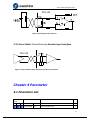
Chapter 4 Parameter........................................................................................................................24
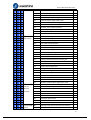
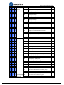
4.1 Parameter List ...................................................................................................................24
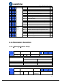
4.2 Parameter Function ...........................................................................................................27
4.2.1【Classify0】Basic Setup.......................................................................................27
4.2.2【Classify 1 】Gain Adjust ...................................................................................32
4.2.3 【Classify 2】Vibrate Restrain.............................................................................38
4.2.4【Classify 3】Velocity/ Torque Control.................................................................39
4.2.5【Classify 4】I/F Monitor Setting..........................................................................43
4.2.6【Classify 5】Extended Setup ...............................................................................48
4.2.7【Classify 6】Special Setup...................................................................................51
Chapter 5 Alarm and Processing.....................................................................................................53
5.1 Alarm List .........................................................................................................................53
5.2 Alarm Processing Method.................................................................................................54
Chapter 6 Display and Operation....................................................................................................62
6.1 Introduction.......................................................................................................................62
6
User’s Manual for EL5 Servo
6.2 Panel Display and Panel Operation...................................................................................63
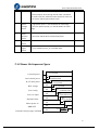
Chapter 7 Power On Run ................................................................................................................75
7.1 Inspection Before Run ......................................................................................................75
7.2 Trial Run ...........................................................................................................................77
7.3 Automatic Control Mode Run...........................................................................................84
7.3.4 Torque Mode ..........................................................................................................91
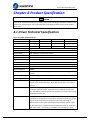
Chapter 8 Product Specification .....................................................................................................94
8.1 Driver Technical Specification..........................................................................................94
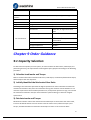
Chapter 9 Order Guidance ..............................................................................................................95
9.1 Capacity Selection ............................................................................................................95
9.2 Electronic Gear Ratio........................................................................................................96
9.3 Stop Feature ......................................................................................................................96
Contact Us ......................................................................................................................................97
7
User’s Manual for EL5 Servo
Chapter 1 Introduction
1.1 Production Introduction
AC servo technically century since the early nineties, the technology has matured, and
continuously improves performance, is now widely used in the field of CNC machine tools,
printing and packaging machinery, textile machinery, and automated production line automation.
EL5-0750 AC servo system is Leadshine R&D new generation full digital AC servo system; adopt
American TI company newest digital signal processor DSP, Large-scale programmable gate array
(CPLD) and MITSUBISHI intelligent power module (IPM), high integration, small size, perfect
protection, good reliability. The optimal PID algorithm to complete the PWM control,
performance has reached the level of similar foreign products.
Compare to the stepper system, EL5-0750 AC servo system has following characteristics:
◆Avoid lost step phenomenon
Servo motor with encoder, position signal feedback to servo driver, formation semi-closed control
system
◆Width ratio, constant torque
Speed ratio is 1:5000, has stability torque features from low speed to high speed
◆High-speed, high-precision
The maximum speed of the servo motor up to 3000rpm, rotation positioning accuracy 1/10000r. T
〖Note〗The different models of the maximum speed of the servo motor.
◆Simple, flexible control
By modifying the parameters of the work of the servo system, the operating characteristics make
the appropriate settings to suit different requirements.
1.2 Inspection of Incoming Goods
1.After receipt, you must check the following:
(1) The box is in good condition, and whether the goods are damaged due to transportation?
(2) Check the servo drive and servo motor nameplate, goods received are the goods?
(3) Check the packing list, the accessories are complete?
Notice
l Damaged or missing parts of the servo system, can not be installed.
l Supporting the use of servo drive must match the performance servo motor.
l After receiving have any questions, please contact with the vendor or company
2 Type meaning
8
User’s Manual for EL5 Servo
⑴EL5 series servo driver
EL5-D-0750
Maximum Output Power
750:750W
High voltage AC servo drive (220 VAC)
⑵Servo motor type
The EL5-D0750 AC servo drive can be used with a variety of domestic and foreign servo motor
matching, selected by the user ordering.
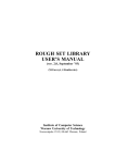
1.3 Production Appearance
1. EL5 series AC servo driver appearance.
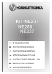
2. Servo motor appearance.
9
User’s Manual for EL5 Servo
3. Accessory
EL5-0750 servo drive standard accessories
① installation manual (this book) a book
② CN1 connector (DB44 hole) a set
③ CN2 plug (DB15 pin) a set
〖Note〗: The ACH750 supporting the PC debugging software needed to be purchased separately.
Chapter 2 Installation
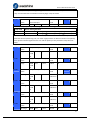
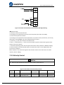
2.1 Storage and Installation Circumstance
Figure 3.1 Servo Driver, Servo Motor Storage Circumstance Demand
Item
EL5 series driver
Match servo motor
Temperature
-20-80℃
-25-70℃
Humility
Under 90%RH (non-condensate)
Under 80%RH(non-condensate)
Atmospheric
environment
Indoor(no exposure)no corrosive gas,
flammable, oil or dust
Indoor(no exposure)no corrosive gas,
flammable, oil or dust
Normal high
Under elevation 1000m
Under elevation 2500m
Vibrate
Less than 0.5G (4.9m/s2) 10-60Hz (non-continuous transport)
Protection
level
IP00(no protection)
IP65
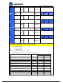
Figure 3.2 Servo Driver, Servo Motor Installation Circumstance Demand
10
User’s Manual for EL5 Servo
Item
EL5 series driver
Match servo motor
Temperature
0-55℃
-25-40℃
Humility
Under 90%RH (non-condensate)
Under 90%RH(non-condensate)
Atmospheric
environment
Indoor(no exposure)no corrosive gas,
flammable, oil or dust
Indoor(no exposure)no corrosive gas,
flammable, oil or dust
Normal high
Under elevation 1000m
Under elevation 2500m
Vibrate
Less than 0.5G (4.9m/s2) 10-60Hz (non-continuous transport)
Protection
level
IP00(no protection)
IP65
2.2 Servo Driver Installation
Notice
l
Servo driver must be installing in the good protection cabinet.
l
The servo drive must be in the specified direction and intervals installed, and ensure good
heat dissipation conditions.
l
May not install surface or nearby of flammable, prevent fire hazard.
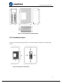
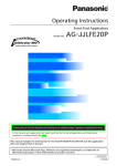
2.2.1 Installation Method
Users can use the backplane mounting or panel mounting installation, mounting direction
perpendicular to the mounting face up. 2.1 chassis installation diagram.
11
User’s Manual for EL5 Servo
Figure 2.1 Driver Baseboard Installs Method
2.2.2 Installation Space
In order to ensure good cooling conditions, the actual installation should be as leaving a larger
interval.
Figure 2-2 Single Driver Install Space
12
User’s Manual for EL5 Servo
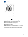
Figure 2-3 Many Sets of Driver Install Space
2.3 Servo Motor Installation
Notice
l
Dismantling belt wheel should be used when the screw dismounting tool.
l
No knocking motor shaft or encoders, prevent motor by vibration or shock.
l
Handling motor may drag the motor shaft, pin out or encoder.
l
Motor shaft does not bear the axial load, radial load, otherwise you may damage the motor.
l
Suggested the use of elastic coupling.
l
Motor installation must be solid, and locking measures, fixed motor with the fastening lock
washer
Install method:
EL5 series servo motor by supporting flange installation, electrical installation in arbitrary
direction.
13
User’s Manual for EL5 Servo
Chapter 3 Wiring
Warning
l
The workers of participation in connect wiring or check must be possess sufficient ability do
this job.
l
The wiring and check must be going on after five minutes in power off.
Caution
l
Must be according to terminal voltage and polar wiring, prevent equipment damage or
worker injury
l
Driver and servo motor must be connect ground good
3.1 Wiring
3.1.1 Wire Gauge
⑴Power supply terminal TB
● Diameter: R, S, T, PE, U, V, W terminals diameter ≥ 1.5mm2 (AWG14-16), r, t terminal diameter
≥ 1.0 mm2 (AWG16-18).
● Ground: The ground wire should be as thick as possible, drive servo motor the PE terminal
point ground, ground resistance <100 Ω.
● Proposed by the three-phase isolation transformer power supply, to reduce the possibility of
electrical burns people. Recommend power by the noise filter supply; improve the anti-jamming
capability.
● Installation fuse (NFB) breaker promptly cut off the external power supply, drive failure.
(2) The control signal CN1 feedback signal CN2
● Diameter: shielded cable (the best selection of shield cable), the diameter ≥ 0.12mm2
(AWG24-26), the shield should be connected to FG terminal.
● Length of line: cable length as short as possible and not more than 3 meters control CN1 cable,
the CN2 cable length of the feedback signal is not more than 20 meters.
● Wiring: away from the power line wiring, to prevent interference string into.
● To the relevant line in the inductive element (coil), install a surge absorbing element: DC coil
reverse parallel freewheeling diode AC coil parallel RC snubber circuit. .
Notice
14
User’s Manual for EL5 Servo
l
U, V, W, and the motor windings a one-to-one connection, not reverse polarity.
l
Cables and wires to be fixed, and avoid close to the radiator and motor drive, so as not to be
reduced due to the heat insulation properties.
l
Large-capacity electrolytic capacitor in the servo drive, even after the power is turned off,
and will continue to keep the pressure up to 5 minutes after the power failure, do not touch
the drive and motor.
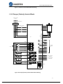
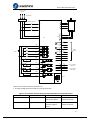
3.1.2 Position Control Mode
1 phase or 3 phase
220VAC
Circuit Braker
Noise Filter
U
Magnetic Contactor
R
V
W
S
PE
T
r
CN2
CN1
t
PUL+
3
PUL-
4
DIR+
5
DIR-
6
23
24
COM+
1
Srom
2 4.7K
PL
7 4.7K
12~24V
RL
8
4.7K
4.7K
ZS
9
RDY
32
ALM
Pcod
33
A+
A-
25
B+
26
B-
27
Z+
28
Z-
22
5V
30
AGND
29
CHZ
39
AI1
41
AGN
D
43
A3I+
44
A3I-
Encoder
Output
-10V to +10V input
(Single-end)
-10V to +10V input
(Differential)
34
CN4
1 3 5
COM-
35
2 4 6
BRK
RS232
31
15
User’s Manual for EL5 Servo
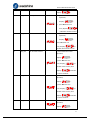
Figure 3-1 Position Control Mode Normal Wiring
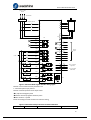
3.1.3 Torque /Velocity Control Mode
1 phase or 3 phase
220VAC
Circuit Braker
Noise Filter
U
Magnetic Contactor
R
V
W
S
PE
T
r
CN2
CN1
t
23
24
COM+
2 4.7K
PL
7 4.7K
RL
4.7K
12~24V
8
4.7K
ZS
9
RDY
32
Pcod
A-
1
Srom
ALM
A+
25
B+
26
B-
27
Z+
28
Z-
22
5V
30
AGND
29
CHZ
39
AI1
41
AGN
D
43
A3I+
44
A3I-
Encoder
Output
33
34
BRK
35
COM-
31
-10V to +10V input
(Single-end)
-10V to +10V input
(Differential)
CN4
1 3 5
2 4 6
RS232
Figure 3-2 Torque/Velocity Control Mode Normal Wiring
16
User’s Manual for EL5 Servo
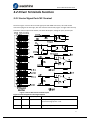
3.2 Driver Terminals Function
3.2.1 Control Signal Port-CN1 Terminal
The left in Figure 3.3 servo drive control signal port CN1 DB44 connectors, drive side socket
connection plug for the hole type, with the controller side needle; Figure 3.3 right side of the top
to bottom of the SI input of the switch, the switch SO outputs, analog A1 input, the A3 input.
Figure 3-3 Servo Driver Port Terminal Layout
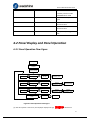
Figure3.1 Control Signal Port-CN1 Signal Explain
Subscript
Signal
Input/output
Name and Explain
1
COM+
input
Public power supply positive terminal of the external
input control signal, 12V ~ 24V
2
SI1
input
Digital input signal 1, default active low maximum
17
User’s Manual for EL5 Servo
input 24V
3
PUL+
input
Enter the positive and negative terminals,
respectively, for pulse TTL level (5V), the rising edge of
default
Effect
4
PUL-
input
5
DIR+
input
6
DIR-
input
Respectively, the direction of the input to the positive
terminal and a negative terminal, TTL level (5V),
default optocoupler deadline
As a positive direction
7
SI2
input
Digital input signal 2,default low level is effect
Maximum input 24V
8
SI3
input
Digital input signal 3,default low level is effect
Maximum input 24V
9
SI4
input
Digital input signal 4,default low level is effect
Maximum input 24V
10
SI5
input
Digital input signal 5,default low level is effect
Maximum input 24V
11
SI6
input
Digital input signal 6,default low level is effect
Maximum input 24V
12
SI9
input
Digital input signal 9,default low level is effect
Maximum input 24V
13
SI7
input
Digital input signal 7,default low level is effect
Maximum input 24V
14
SI8
input
Digital input signal 8,default low level is effect
Maximum input 24V
22
+5V
output
Reserve, encoder signal output +5V
23
A+
output
24
A-
output
Motor encoder A phase positive, negative different
output terminal
25
B+
output
26
B-
output
27
Z+
output
28
Z-
output
Motor encoder Z phase positive, negative different
output terminal
29
OCZ
output
Z signal OC output
30
GND5V
output
Encoder signal output power ground
31
COM-
output
Digital output signal commonality ground
32
SO2
output
Digital output signal 2
33
SO1
output
Digital output signal 1
34
SO3
output
Digital output signal 3
Motor encoder B phase positive, negative different
output terminal
18
User’s Manual for EL5 Servo
35
SO4
output
Digital output signal 4
36
SO5
output
Digital output signal 5
37
SO6
output
Digital output signal 6
39
AI1
input
Analog input 1,input voltage range -10-10V,input
resistor 20KΩ
40
+15VA
output
Reserve output inner 15V,less than 50mA
41
GND15VA
output
Reserve,+15V ground
43
AI3+
input
Analog input 3 positive, negative, input voltage range
-10-10V,input resistor 20KΩ
44
AI3-
input
15-21,38,
42
NC
/
Not connect
Shell
FG
/
Shield ground
3.2.2 Encoder Input Port-CN2 Terminal
Figure 3.2 Encoder Input Port-CN2 Terminal Signal Explain
Pin
Signal
Name
1
EA+
Encoder channel A+ input
2
EB+
Encoder channel B+ input
3
EGND
Signal ground
4
Hall W+
Hall sensor W+ input
5
Hall U+
Hall sensor U+ input
6
FG
Ground terminal for shielded
7
EZ+
Encoder channel Z+ input
8
EZ-
Encoder channel Z- input
9
Hall V+
Hall sensor V+ input
10
Hall V-
Hall sensor V- input
11
EA-
Encoder channel A- input
12
EB-
Encoder channel B- input
13
VCC
+5V @ 100 mA max.
14
Hall W-
Hall sensor W- input
15
Hall U-
Hall sensor U- input
Terminal Arrange Figure
3.2.3 Communication Port
Figure 3.3 Connect STU Port-CN4 Signal Explain
RS232
May via dedicated series cable connect PC or STU, prohibit insertion power on, and
suggest use twisted-pair or shielded wire. the wire long is less than 2 meter
19
User’s Manual for EL5 Servo
RS485
Suggest adopt shield twisted-pair.
Terminal
signal
name
1
GND
Power ground
2
TxD
RS232 send terminal
3
5V
Reserve, provide current less than
50mA
4
RxD
RS232 receive terminal
5
RS485
+
Reserve,RS485+/A
6
RS485
-
Reserve,RS485-/B
Figure 3.4 Driver interconnect interface-CN3 signal explain
RS485
Terminal
signal
name
1
GND
Power ground
2
NC
Not connect
3
5V
Reserve, provide current less than
50mA
4
NC
Not connect
5
RS485
+
Reserve,RS485+/A
6
RS485
-
Reserve,RS485-/B
3.2.4 Power Port
Figure 3.5 Main Power Input Port-CN5
Terminal
Signal
Name
1
R
2
S
3
T
Drive the main power input: connecting 3-phase 220Vac (line voltage);
orders phase 220Vac, the hot and neutral should be connected to the R
and T both ends.
4
BR
Outside brake resistor input terminal
5
P+
DC busbar voltage+
Outside brake resistor
connect between BR
and P+
Figure 3.6 Control Power Input Port-CN6
Terminal
Signal
Name
1
U
3 phase motor power input
2
V
3
W
4
PE
Frame ground
20
User’s Manual for EL5 Servo
5
r
Control power
input 1
t
Control power
input 2
Control power voltage range between 1 and
2:85Vac-265Vac
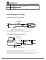
3.3 I/O Interface Principle
3.3.1 Switch Value Input Interface
Figure 3-4 Switch Value Input Interface
⑴The user provide power, DC 12-24V,current≥100mA
⑵Notice, if current polar connect reverse, will make servo driver can’t run.
3.3.2 Switch Value Output Interface
Figure 3.5 Switch Value Output Interface
(1) The external power supply is provided by the user, but care must be taken, if the power
supply polarity reversal, the servo drive is damaged.
(2) The output of the form of open-collector maximum voltage of 25V, maximum current of 50mA,
external power supply. Therefore, the load switch output signal must meet the limited
21
User’s Manual for EL5 Servo
requirements. If you exceed the limit requirements or output directly connected with the power
supply, the servo drive is damaged.
(3) If the load is inductive loads relays, etc., must be anti-parallel freewheeling diode across the
load. If the freewheeling diode connected reversely, the servo drive is damaged.
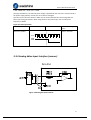
3.3.3 Pulse Value Input Interface
Figure 3-6 Pulse Value Input Interface Different Drive Mode
Vcc =12V,
Vcc =24V,
R select 1K,0.25W
R select 2K,0.25W
Figure3-7 Pulse Value Input Interface Single Terminal Drive Mode
(1) In order to properly transmit pulse volume data, we recommend using the differential drive
mode.
(2) The differential drive mode, AM26LS31, MC3487 or similar RS422 line drive.
(3) The use of single-ended drive, will make the operation frequency reduced. Pulse input circuit,
drive current 10 ~~ 15mA, limited the maximum voltage of 25V external power supply conditions
to determine the value of the resistance R. Empirical data: VCC = 24V, R = 1.3 to 2K; VCC = 12V, R
22
User’s Manual for EL5 Servo
= 510 ~ 820Ω; VCC = 5V, R = 82 ~~ 120Ω.
(4) Single-ended drive, the external power supply is provided by the user, but it must be noted, if
the power supply polarity reversal, the servo drive is damaged.
(5) Pulse input in the form shown in Table 3.4, the arrows indicates the count along Table 3.5
pulse input timing parameters. When using the form of 2-phase input, the 4 octave pulse
frequency ≤ 500kH.
Figure 3.7 Pulse Input Form
Pulse command form
CCW
CW
Pulse train symbol
Parameter setting
value
Pulse + direction
3.3.4 Analog Value Input Interface (reserve)
Figure 3-8 Analog AI1 Input Interface
23
User’s Manual for EL5 Servo
Figure 3-9 Analog AI3 Input Interface
3.3.5 Servo Motor Photo Electricity Encoder Input Interface
Figure 3-10 Servo Motor Photo Electricity Encoder Input Interface
Chapter 4 Parameter
4.1 Parameter List
Related
Mode
Parameter Number
P
S
T
Classify
P
S
T
【Classify0】 01
Name
Number
Control mode setup
24
User’s Manual for EL5 Servo
P
S
T
P
S
P
S
Gain Adjust
02
Setup Auto-adjust
T
03
Mechanical rigidity setup
T
04
Ratio of inertia
P
06
Command pulse polar setup
P
07
Command pulse input mode setup
P
09
1st numerator of electronic gear
P
10
Denominator of electronic gear
P
S
T
11
Encoder pulse output molecular
P
S
T
12
Pulse output logic reverse
P
S
T
13
1st torque limit
P
14
Position deviation setup
P
P
S
T
【Classify1】 00
Gain Adjust
01
P
S
T
02
1st velocity loop integration time constant
P
S
T
03
1st velocity detection filter
P
S
T
04
1st torque filter
05
2nd position loop gain
P
1st position loop gain
1st velocity loop gain
P
S
T
06
2nd velocity loop gain
P
S
T
07
2nd velocity loop integration time constant
P
S
T
08
2nd velocity detection filter
P
S
T
09
2nd torque filter
P
10
Velocity feed forward time constant gain
P
11
Feed forward filter time constant
P
S
12
Torque feed forward gain
P
S
13
Torque feed forward filter
P
S
14
2nd gain setup
P
15
Control switching mode
P
17
Control switching level
P
18
Control switch hysteresis
P
19
Gain switching time
P
35
Position command filter setup
36
Encoder feedback pulse digital filter setup
00
Self-adaption filter mode setup
01
1st notch frequency
02
1st notch width select
03
1st notch depth select
T
P
S
P
S
P
S
T
P
S
T
P
S
T
P
S
T
04
2nd notch frequency
P
S
T
05
2nd notch width select
P
S
T
06
2nd notch depth select
P
22
Position command smooth filter
P
23
Position command FIR filter
S
S
T
【Classify2】
Vibrate
Restrain
Function
【Classify3】 00
Speed,
01
Velocity setup internal and external switching
Speed command direction appoint select
25
User’s Manual for EL5 Servo
S
T
02
Speed command input gain
03
Speed command input reversal
S
04
1st speed setup
S
05
2nd speed setup
S
06
3rd speed setup
S
07
4th speed setup
S
08
5th speed setup
S
09
6th speed setup
S
10
7th speed setup
S
11
8th speed setup
S
12
Acceleration time setup
S
13
Deceleration time setup
S
14
Sigmoid acceleration/deceleration time setup
T
16
Zero-clamp level
T
18
Torque command direction selection
T
19
Torque command input gain
T
20
Torque command input reversal
T
21
Speed limit value 1
Motor rotate maximum speed
S
S
Torque
Control
P
S
T
24
P
S
T
SI 1 input selection
P
S
T
P
S
T
【Classify4】 00
I/F Monitor
01
Setting
02
P
S
T
03
SI 4 input selection
P
S
T
04
SI 5 input selection
P
S
T
10
SO 1 output selection
P
S
T
11
SO 2 output selection
P
S
T
12
SO 3 output selection
P
S
T
13
SO 4 output selection
P
S
T
22
Analog input 1(AI 1) offset setup
P
S
T
23
Analog input 1(AI 1) filter
P
S
T
28
Analog input 3(AI 3) offset setup
P
S
T
29
Analog input 3(AI 3) filter
P
31
Positioning complete range
P
32
Positioning complete output setup
P
33
INP hold time
34
Zero-speed
35
Speed coincidence range
P
S
T
S
SI 2 input selection
SI 3 input selection
P
S
T
36
At-speed
P
S
T
37
Mechanical brake action at stalling setup
P
S
T
38
Mechanical brake action at running setup
P
S
T
39
Brake release speed setup
P
P
【Classify5】 00
Extended
01
2nd numerator of electronic gear
3rd numerator of electronic gear
26
User’s Manual for EL5 Servo
P
Setup
02
4th numerator of electronic gear
P
S
T
03
Denominator of pulse output division
P
S
T
06
Sequence at servo-off
P
S
T
08
Main power off LV trip selection
P
S
T
09
Main power off detection time
P
S
T
13
Over-speed level setup
P
S
T
15
I/F reading filter
P
S
T
28
LED initial status
P
S
T
29
RS232 communication baud rate setup
P
S
T
30
RS485 communication baud rate setup
P
S
T
31
Axis address
P
S
T
35
Front panel lock setup
P
S
T
P
S
T
P
S
T
【Classify6】 03
Special
04
Setup
08
P
S
T
09
Negative direction torque compensation value
P
20
Trial running distance
P
21
Trial running wait time
P
22
Trial running cycle times
JOG trial run command torque
JOG trial run command speed
Positive direction torque compensation value
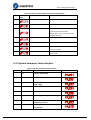
4.2 Parameter Function
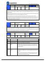
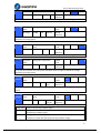
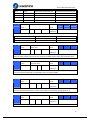
4.2.1【Classify0】Basic Setup
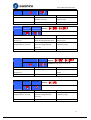
Pr0.01*
Parameter
Name
Control Mode
Setup
Set range
0-2
Unit
-
Related
Mode
P
Normal Default Set
0
S
T
S
T
Set using control mode
Setup value
Content
1st mode
2nd mode
0
Position
-
1
Velocity
-
2
Torque
-
Pr0.02
Parameter
Name
Real-time Auto-gain Tuning
Setup
Related
Mode
P
Set Range
0-2
Normal
Default Set
0
Unit
-
27
User’s Manual for EL5 Servo
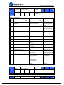
You can set up the action mode of the real-time auto-gain tuning.
Setup value
mode
Varying degree of load inertia in motion
0
invalid
Real-time auto-gain tuning function is disabled.
1
standard
Basic mode. do not use unbalanced load, friction compensation or
gain switching
2
positioning
Main application is positioning. it is recommended to use this
mode on equipment without unbalanced horizontal axis, ball
screw driving equipment with low friction, etc.
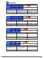
Pr0.03
Parameter
Name
Selection of Machine
Stiffness at Real-time
Auto-gain Tuning
Related
Mode
P
Set Range
0-31
Normal
Default Set
11
Unit
-
S
T
You can set up response while the real-time auto-gain tuning is valid.
Notice: Higher the setup value, higher the velocity response and servo stiffness will be obtained.
However, when increasing the value, check the resulting operation to avoid oscillation or
vibration.
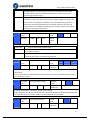
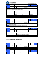
Pr0.04
Parameter
Name
Ratio of Inertia
Set Range
0-10000
Unit
%
Related
Mode
P
Normal
Default Set
250
S
T
28
User’s Manual for EL5 Servo
You can set up the ratio of the load inertia against the rotor(of the motor)inertia.
Pr0.04=( load inertia/rotate inertia)×100%
Notice:
If the inertia ratio is correctly set, the setup unit of Pr1.01 and Pr1.06 becomes (Hz). When the
inertia ratio of Pr0.04 is larger than the actual, the setup unit of the velocity loop gain becomes
larger, and when the inertia ratio of Pr0.04 is smaller than the actual, the setup unit of the
velocity loop gain becomes smaller.
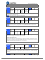
Pr0.06*
Parameter
Name
Command Pulse Rotational
Direction Setup
Related
Mode
P
Set Range
0-1
Normal
Default Set
0
Unit
-
Set command pulse input rotate direction, command pulse input type
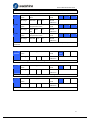
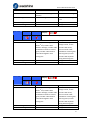
Pr0.07*
Parameter
Name
Command Pulse Input
Mode Setup
Related
Mode
P
Set Range
0-3
Normal
Default Set
1
Unit
-
Pr0.06
Pr0.07
Command Pulse
Format
Signal Title
0
0 or 2
90 phase
difference
2-phase pulse(A
phase +B phase)
Pulse sign
1
Positive direction
pulse + negative
direction pulse
Pulse sign
3
Pulse + sign
Pulse sign
0 or 2
90 phase
difference
2 phase pulse(A
phase +B phase)
Pulse sign
1
Positive direction
pulse + negative
direction pulse
Pulse sign
3
Pulse + sign
Pulse sign
1
Positive
Direction
Command
Negative
Direction
Command
29
User’s Manual for EL5 Servo
Command pulse input signal allow largest frequency and smallest time width
PULS/SIGN Signal Input I/F
Pulse
series
interface
Pr0.09
Permissible
Max. Input
Frequency
Smallest Time Width
t1
t2
t3
t4
t5
t6
Long distance
interface
500kpps
2
1
1
1
1
1
Open-collecto
r output
200kpps
5
2.5
2.5
2.5
2.5
2.5
Parameter
Name
Command Pulse Polar Set
Related
Mode
P
Set Range
1-32767
Normal
Default Set
1
unit
-
Set command pulse input frequency divide, frequency double process
Pr0.10
Parameter
Name
Command Pulse Input
Mode Set
Related
Mode
P
Set Range
1-32767
Normal
Default Set
1
Unit
-
Set command pulse input divide frequency, double frequency process denominator
Pr0.09
Pr0.10
1-3276
7
1-3276
7
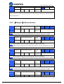
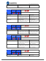
Pr0.11*
command
Parameter
Name
Command Pulse Polar Set
Related
Mode
P
Set Range
1-2500
Normal
Default Set
2500
Unit
P/r
S
T
S
T
Set encoder divide frequency output resolution
Pr5.03*
Parameter
Name
Pulse Output Divide
Frequency Denominator
Related
Mode
P
Set Range
1-2500
Normal
Default Set
2500
Unit
-
Pr0.11 motor output pulse rotate 1 and Pr5.03 pulse output divide frequency denominator
30
User’s Manual for EL5 Servo
1-2500
1-2500
Pulse output resolution after divide double frequency 4 times
Pr0.12*
Parameter
Name
Pulse Output Logic Reversal
Related
Mode
P
Set Range
0-2
Normal
Default Set
0
Unit
-
S
T
You can set up the B phase logic and the output source of the pulse output. With this parameter,
you can reverse the phase relation between the A-phase pulse and B-phase pulse by reversing
the B-phase logic.
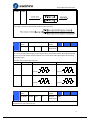
<encoder pulse output logic reversal>
Pr0.12
B-phase Logic
CCW Direction Rotation
CW Direction Rotation
0
Non-Reversal
A phase
A phase
B phase
B phase
A phase
A phase
B phase
B phase
1
Pr0.13
Reversal
Parameter
Name
1st Torque Limit
Set Range
0-500
Unit
%
Related
Mode
P
Normal
Default Set
300
S
T
You can set up the limit value of the motor output torque, as motor rate current %,the value can’t
beyond driver max output current.
31
User’s Manual for EL5 Servo
Pr0.14
Parameter
Name
Position Deviation Excess
Setup
Related
Mode
P
Set Range
0-500
Normal
Default Set
200
Unit
0.1rev
S
T
Adopt encoder pulse as unit, if setup over-small, will appear fault Err24.0(Position deviation
over-large abnormal detection)
4.2.2【Classify 1 】Gain Adjust
Pr1.00
Parameter
Name
1st Gain of Position Loop
Related
Mode
P
Set Range
0-30000
Normal
Default Set
320
Unit
0.1/s
You can determine the response of the positional control system. Higher the gain of position loop
you set, faster the positioning time you can obtain. Note that too high setup may cause
oscillation.
Pr1.01
Parameter
Name
1st Gain of Velocity Loop
Related
Mode
P
Set Range
0-32767
Normal
Default Set
180
Unit
0.1Hz
S
T
You can determine the response of the velocity loop. In order to increase the response of overall
servo system by setting high position loop gain, you need higher setup of this velocity loop gain
as well. However, too high setup may cause oscillation.
Notice:when the inertia ratio of Pr0.04 is set correctly, the setup unit of Pr1.01 becomes (HZ)
Pr1.02
Parameter
Name
1st Time Constant of
Velocity Loop Integration
Related
Mode
P
Set Range
0-10000
Normal
Default Set
310
Unit
0.1ms
S
T
You can set up the integration time constant of velocity loop, Smaller the set up, faster you can
dog-in deviation at stall to 0.The integration will be maintained by setting to”9999”.The
integration effect will be lost by setting to”10000”.
Pr1.03
Parameter
Name
1st Filter of Velocity
Detection
Related
Mode
P
S
T
32
User’s Manual for EL5 Servo
Set Range
0-31
Unit
-
Normal
Default Set
15
You can set up the time constant of the low pass filter (LPF) after the speed detection, in 32 steps
(0 to 31).
Higher the setup, larger the time constant you can obtain so that you can decrease the motor
noise, however, response becomes slow.
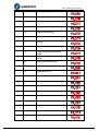
The loop gain to set the filter parameters, referring to the following table:
Set Value
Speed Detection Filter Cut-off
Frequency(HZ)
Set
Value
Speed Detection Filter Cut-off
Frequency(HZ)
0
2500
16
750
1
2250
17
700
2
2100
18
650
3
2000
19
600
4
1800
20
550
5
1600
21
500
6
1500
22
450
7
1400
23
400
8
1300
24
350
9
1200
25
300
10
1100
26
250
11
1000
27
200
12
950
28
175
13
900
29
150
14
850
30
125
15
800
31
100
Pr1.04
Parameter
Name
1st Time Constant of Torque
Filter
Related
Mode
P
Set Range
0-250
0
Normal
Default Set
126
Unit
0.01ms
S
T
You can set up the time constant of the 1st delay filter inserted in the torque command portion.
You might expect suppression of oscillation caused by distortion resonance.
Pr1.05
Pr1.06
Parameter
Name
2nd Gain of Position Loop
Related
Mode
P
Set Range
0-300
00
Normal
Default Set
380
Parameter
2nd Velocity Loop Gain
Unit
0.1/s
Related
P
S
T
33
User’s Manual for EL5 Servo
Name
Pr1.07
Pr1.08
Pr1.09
Mode
Set Range
0-327
67
Parameter
Name
Unit
Normal
Default Set
180
2nd Velocity Loop
Integration Time Constant
Related
Mode
P
Set Range
0-100
00
Normal
Default Set
10000
Parameter
Name
2nd Velocity Detection
Filter
Related
Mode
P
Set Range
0-31
Normal
Default Set
15
Parameter
Name
2nd Torque Filter
Set Range
0-250
0
Unit
Unit
Unit
0.1HZ
0.1ms
-
0.01ms
Related
Mode
P
S
Normal
Default Set
126
S
T
S
T
T
Position loop, velocity loop, velocity detection filter, torque command filter have their 2 pairs of
gain or time constant.
Pr1.10
Parameter
Name
Speed Feed Forward
Constant Gain
Related
Mode
P
Set Range
0-100
0
Normal
Default Set
300
Unit
0.10%
Multiply the speed control command calculated according to the internal positional command by
the ratio of this parameter and add the result to the speed command resulting from the
positional control process.
Pr1.11
Parameter
Name
Speed Feed Forward
Constant Gain
Related
Mode
P
Set Range
0-640
0
Normal
Default Set
50
Unit
0.01ms
Set the time constant of 1st delay filter which affects the input of speed feed forward.
(speed feed forward use)
The velocity feed forward will become effective as the velocity feed forward gain is gradually
increased with the speed feed forward filter set at approx.50 (0.5ms). The positional deviation
during operation at a constant speed is reduced as shown in the equation below in proportion to
the value of velocity feed forward gain.
Position deviation [command unit]=command speed [command unit/s]/position loop
gain[1/s]×(100-speed feed forward gain[%]/100
Pr1.12
Parameter
Torque feed forward gain
Related
P
S
34
User’s Manual for EL5 Servo
name
Set range
mode
0-100
0
unit
0.1%
Normal
default
set
0
Multiply the torque control command calculated according to the velocity control command by
the ratio of this parameter and add the result to the torque command resulting from the velocity
control process.
When use torque feed forward, need to set ratio of inertia correctly, please will use machine each
element calculate ratio of inertia setup Pr0.04[ratio of inertia]
Position deviation at a constant acceleration/deceleration can be minimized close to 0 by
increasing the torque feed forward gain ,this means that position deviation can be maintained at
near 0 over entire operation while driving in trapezoidal speed pattern under ideal condition
where disturbance torque is not active.
Pr1.13
Parameter
name
Torque feed forward filter
time constant
Related
mode
P
Set range
0-640
0
Normal
default set
0
unit
0.01ms
S
Set up the time constant of 1st delay filter which affects the input of torque feed forward.
zero positional deviation is impossible in actual situation because of disturbance torque. as with
the velocity feed forward, large torque feed forward filter time constant decreases the operating
noise but increases positional deviation at acceleration change point.
Pr1.15
Parameter
name
Control switching mode
Related
mode
P
Set range
0-10
Normal
default set
0
unit
-
Setting
value
Switching condition
Gain switching condition
0
Fixed to 1st gain
Fixed to the 1st gain (Pr1.00-Pr1.04)
1
Fixed to 2nd gain
Fixed to the 2nd gain (Pr1.05-Pr1.09)
2
with gain switching
input
1st gain when the gain switching input is open.
2nd gain when the gain switching input is connected to com- .
If no input signal is allocated to the gain switching input, the
1st gain is fixed.
3
Torque command is
large
Shift to the 2nd gain when the absolute value of the torque
command exceeded (level + hysteresis)[%]previously with the
1st gain.
Return to the 1st gain when the absolute value of the torque
command was kept below (level + hysteresis)[%]previously
during delay time with the 2nd gain.
35
User’s Manual for EL5 Servo
4
reserve
reserve
5
Speed command is
large
Valid for position and speed controls.
Shift to the 2nd gain when the absolute value of the speed
command exceeded (level + hysteresis)[r/min]previously with
the 1st gain.
Return to the 1st gain when the absolute value of the speed
command was kept below (level + hysteresis)[r/min]previously
during delay time with the 2nd gain.
6
Position deviation is
large
Valid for position control.
Shift to the 2nd gain when the absolute value of the positional
deviation exceeded (level + hysteresis)[pulse]previously with
the 1st gain.
Return to the 1st gain when the absolute value of the
positional deviation was kept below (level +
hysteresis)[r/min]previously during delay time with the 2nd
gain.
Unit of level and hysteresis [pulse] is set as the encoder
resolution for positional control.
7
with position
command
Valid for position control.
Shift to the 2nd gain when the positional command was not 0
previously with the 1st gain.
Return to the 1st gain when the positional command was kept
0 previously during delay time with the 2nd gain.
8
Not in positioning
complete
Valid for position control.
Shift to the 2nd gain when the positioning was not completed
previously with the 1st gain.
Return to the 1st gain when the positioning was kept in
completed condition previously during delay time with the
2nd gain.
9
Actual speed is
large
10
Have position
command +actual
speed
Position control is effect
In the first gain, if the position command is not zero, transfer
to the second gain
In the second gain, if the position command is zero and
continue in delay time period, and actual speed absolute value
less than (grade-hysteresis)[r/min],back to the first gain
When position control, may setup Pr1.15=3,5,6,9,10;
When speed control, may setup Pr1.15=3,5,9;
36
User’s Manual for EL5 Servo
Pr1.17
Parameter
name
Control switching level
Related
mode
P
Set range
0-200
00
Normal
default set
50
unit
Accordi
ng to
mode
Unit of setting varies with switching mode. switching condition: position is encoder pulse
number, speed is r/min, torque is %.
Notice: set the level equal to or higher than the hysteresis.
Pr1.18
Parameter
name
Control switching hysteresis
Related
mode
P
Set range
0-200
00
Normal
default
set
33
unit
Accordi
ng to
mode
Combine Pr1.17(control switching level)setup
Notice: when level< hysteresis, the hysteresis is internally adjusted so that it is equal to level.
Pr1.19
Parameter
name
gain switching time
Set range
0-100
00
unit
0.1ms
Related
e mode
P
Normal
default
set
33
For position controlling: if the difference between 1st gain and 2nd gain is large, the increasing
rate of position loop gain can be limited by this parameter.
<Position gain switching time>
Notice: when using position control, position loop gain rapidly changes, causing torque change
and vibrate. By adjusting Pr1.19 position loop gain switching time, increasing rate of the position
loop gain can be decreased and variation level can be reduced.
Pr1.35*
Parameter
name
Position specify filter setup
Related
mode
P
Set range
0-200
Normal
default set
0
unit
0.05us
To position given pulse do filtering, eliminate the interference of the narrow pulse, over-large
setup will influence the receive of high frequency position command pulse, and will bring larger
delay time.
Pr1.36*
Parameter
Encoder feedback pulse
Related
P
37
User’s Manual for EL5 Servo
name
digital filter setup
Set range
0-200
unit
mode
0.05us
Normal
default set
0
To encoder feedback pulse do filtering, eliminate the interference of the narrow pulse, over-large
setup will influence motor high speed running, and will bring larger delay time, influence motor
control performance.
4.2.3 【Classify 2】Vibrate Restrain
Pr2.0.1
Parameter
name
1st notch frequency
Related
mode
P
Set range
50-20
00
Normal
default set
2000
unit
HZ
S
T
Set the center frequency of the 1st notch filter
Notice: the notch filter function will be invalidated by setting up this parameter to “2000”.
Pr2.0.2
Parameter
name
1st notch width selection
Related
mode
P
Set range
0-20
Normal
default set
2
unit
-
S
T
Set the width of notch at the center frequency of the 1st notch filter.
Notice: Higher the setup, larger the notch width you can obtain. Use with default setup in normal
operation.
Pr2.0.3
Parameter
name
1st notch depth selection
Related
mode
P
Set range
0-99
Normal
default set
0
unit
-
S
T
Set the depth of notch at the center frequency of the 1st notch filter.
Notice: Higher the setup, shallower the notch depth and smaller the phase delay you can obtain.
Pr2.0.4
Parameter
name
2nd notch frequency
Related
mode
P
Set range
50-20
00
Normal
default set
2000
unit
HZ
S
T
Set the center frequency of the 2nd notch filter
Notice: the notch filter function will be invalidated by setting up this parameter to “2000”.
Pr2.0.5
Parameter
name
2nd notch width selection
Related
mode
P
Set range
0-20
Normal
2
unit
-
S
T
38
User’s Manual for EL5 Servo
default set
Set the width of notch at the center frequency of the 2nd notch filter.
Notice: Higher the setup, larger the notch width you can obtain. Use with default setup in normal
operation.
Pr2.0.6
Parameter
name
2nd notch depth selection
Related
mode
P
Set range
0-99
Normal
default set
0
unit
-
S
T
Set the depth of notch at the center frequency of the 2nd notch filter.
Notice: Higher the setup, shallower the notch depth and smaller the phase delay you can obtain.
Pr2.22
Parameter
name
Positional command
smoothing filter
Related
mode
P
Set range
0-327
67
Normal
default
set
0
unit
0.1ms
Set up the time constant of the1st delay filter in response to the positional command.
Pr2.23
Parameter
name
Positional command FIR
filter
Related
mode
P
Set range
0-100
00
Normal
default
set
0
unit
0.1ms
Set up the time constant of the1st delay filter in response to the positional command.
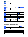
4.2.4【Classify 3】Velocity/ Torque Control
Pr3.00
Parameter
name
Speed setup, Internal
/External switching
Related
mode
Set range
0-3
Normal
default set
unit
-
S
0
This driver is equipped with internal speed setup function so that you can control the speed with
contact inputs only.
Setup value
Speed setup method
0
Analog speed command(SPR)
1
Internal speed command 1st to 4th speed(PR3.04-PR3.07)
2
Internal speed command 1st to 3rd speed (PR3.04-PR3.06),Analog speed
command(SPR)
39
User’s Manual for EL5 Servo
3
Internal speed command 1st to 8th speed (PR3.04-PR3.11)
<relationship between Pr3.00 Internal/External switching speed setup and the internal
command speed selection 1-3 and speed command to be selected>
Setup
value
selection 1 of
internal command
speed(INTSPD1)
selection 2 of
internal command
speed (INTSPD2)
selection 3 of
internal command
speed (INTSPD3)
selection of
Speed
command
1
OFF
OFF
NO effect
1st speed
ON
OFF
2nd speed
OFF
ON
3rd speed
ON
ON
4th speed
OFF
OFF
ON
OFF
2nd speed
OFF
ON
3rd speed
ON
ON
Analog speed
command
2
3
Pr3.01
NO effect
The same as [Pr3.00=1]
1st speed
OFF
1st to 4th
speed
OFF
OFF
ON
5th speed
ON
OFF
ON
6th speed
OFF
ON
ON
7th speed
Parameter
name
Speed command rotational
direction selection
Related
mode
range
0-1
default
unit
-
S
0
Select the Positive /Negative direction specifying method
Setup value
Select speed command
sign(1st to 8th speed)
Speed command
direction (VC-SIGN)
Position command
direction
0
+
No effect
Positive direction
-
No effect
Negative direction
Sign has no effect
OFF
Positive direction
Sign has no effect
ON
Negative direction
1
Pr3.02
Parameter
name
Input gain of speed
command
range
10-20
00
unit
(r/min)/v
Related
mode
default
S
T
500
Based on the voltage applied to the analog speed command (SPR), set up the conversion gain to
motor command speed.
You can set up “slope” of relation between the command input voltage and motor speed, with
Pr3.02. Default is set to Pr3.02=500(r/min)/V, hence input of 6V becomes 3000r/min.
Notice:
1. Do not apply more than ±10V to the speed command input(SPR).
2. When you compose a position loop outside of the driver while you use the driver in velocity
40
User’s Manual for EL5 Servo
control mode, the setup of Pr3.02 gives larger variance to the overall servo system.
3. Pay an extra attention to oscillation caused by larger setup of Pr3.02.
Pr3.03
Parameter
name
Reversal of speed
command input
range
0-1
unit
Related
mode
-
default
S
1
Specify the polarity of the voltage applied to the analog speed command (SPR).
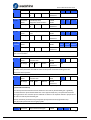
Setup value
Motor rotating direction
0
Non-reversal
[+ voltage]
[+ direction] [- voltage]
[-direction]
1
reversal
[+ voltage]
[- direction] [- voltage]
[+direction]
Caution: When you compose the servo drive system with this driver set to velocity control
mode and external positioning unit, the motor might perform an abnormal action if the polarity
of the speed command signal from the unit and the polarity of this parameter setup does not
match.
Pr3.04
Pr3.05
Pr3.06
Pr3.07
Pr3.08
Pr3.09
Parameter
name
1st speed of speed setup
Related
mode
range
-2000
0-200
00
r/min
default
Parameter
name
2nd speed of speed setup
Related
mode
range
-2000
0-200
00
r/min
default
Parameter
name
3rd speed of speed setup
Related
mode
Set range
-2000
0-200
00
Normal
default set
Parameter
name
4th speed of speed setup
Related
mode
Set range
-2000
0-200
00
Normal
default set
Parameter
name
5th speed of speed setup
Related
mode
Set range
-2000
0-200
00
Normal
default set
Parameter
name
6th speed of speed setup
Related
mode
Set range
-2000
Normal
unit
unit
unit
unit
unit
unit
r/min
r/min
r/min
r/min
S
0
S
0
S
0
S
0
S
0
S
0
41
User’s Manual for EL5 Servo
Pr3.10
Pr3.11
0-200
00
default set
Parameter
name
7th speed of speed setup
Related
mode
Set range
-2000
0-200
00
Normal
default set
Parameter
name
8th speed of speed setup
Related
mode
Set range
-2000
0-200
00
Normal
default set
unit
unit
r/min
r/min
S
0
S
0
Set up internal command speed, 1st to 8th
Pr3.12
Pr3.13
Pr3.14
Pr3.16
Parameter
name
Acceleration time setup
Related
mode
Set range
0-100
00
Normal
default set
Parameter
name
Deceleration time setup
Related
mode
Set range
0-100
00
Normal
default set
Parameter
name
Sigmoid
acceleration/deceleration
time setup
Related
mode
Set range
0-100
0
Normal
default set
Parameter
name
Speed zero clamp level
Related
mode
Set range
10-20
000
Normal
default set
unit
unit
unit
unit
Ms/(100
0r/min)
Ms/(100
0r/min)
ms
r/min
S
100
S
100
S
0
S
T
30
When analog speed given value under speed control mode less than zero speed clamp level
setup, speed command will set to 0 strongly.
Pr3.18
Parameter
name
Torque command direction
selection
Related
mode
Set range
0-1
Normal
default set
unit
-
T
0
select the direction positive/negative direction of torque command
42
User’s Manual for EL5 Servo
0
Specify the direction with the sign of torque command
Torque command input[+]
positive direction, [-]
negative direction
1
Specify the direction with torque command sign(TC-SIGN).
OFF: positive direction ON: negative direction
Pr3.19
Parameter
name
Torque command input gain
Related
mode
Set range
10-10
0
Normal
default set
unit
0.1V/10
0%
T
0
Based on the voltage (V) applied to the analog torque command (TRQR),set up the conversion
gain to torque command(%) .
Pr3.20
Parameter
name
torque command input
reversal
Related
mode
Set range
0-1
Normal
default set
unit
-
T
0
Set up the polarity of the voltage applied to the analog torque command(TRQR).
Setup value
Direction of motor output torque
0
Non-reversal
[+ voltage]
[+ direction] [- voltage]
[-direction]
1
reversal
[+ voltage]
[- direction] [- voltage]
[+direction]
Pr3.21
Parameter
name
Speed limit value 1
Set range
0-200
00
unit
Related
mode
r/min
T
Normal
default set
0
Set up the speed limit used for torque controlling.
During the torque controlling, the speed set by the speed limit value cannot be exceeded.
Pr3.24*
Parameter
name
Motor max rotate speed
Related
mode
P
Set range
0-600
0
Normal
default set
3000
unit
r/min
S
T
Set up motor running max rotate speed, but can’t be exceeded motor allowed max rotate speed.
Notice: have [*] remark parameter indicate control power on vary content is valid
4.2.5【Classify 4】I/F Monitor Setting
Pr4.00*
Parameter
name
SI1 input selection
Related
mode
P
S
T
43
User’s Manual for EL5 Servo
Pr4.01*
Pr4.02*
Pr4.03*
Pr4.04*
Set range
0-00F
FFFFF
h
unit
Parameter
name
The SI2 input select
Set range
0-00F
FFFFF
h
Parameter
name
The SI3 input select
Set range
0-00F
FFFFF
h
Parameter
name
The SI4 input select
Set range
0-00F
FFFFF
h
Parameter
name
The SI5 input select
Set range
0-00F
FFFFF
h
unit
unit
unit
unit
-
-
-
-
-
Normal
default set
00828282h
Related
mode
P
Normal
default set
0081818h
Related
mode
P
Normal
default set
0091910Ah
Related
mode
P
Normal
default set
00060606h
Related
mode
P
Normal
default set
0000100Ch
S
S
S
S
T
T
T
T
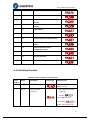
Set SI1 input function allocation.
This parameter use 16 binary system do setup, as following :
00- - - - * * h: position control
00- - * * - - h: velocity control
00* * - - - - h: torque control
Please at [**] partition set up function number
For the function number, please refer to the following Figure.
Signal name
symbol
Set value
A connect
B connect
Invalid
-
00h
Do not setup
Positive direction over-travel inhibition input
POT
01h
81h
negative direction over-travel inhibition input
NOT
02h
82h
Servo-ON input
SRV-ON
03h
83h
Alarm clear input
A-CLR
04h
Do not setup
Gain switching input
GAIN
06h
86h
Deviation counter clear input
CL
07h
Do not setup
Command pulse inhibition input
INH
08h
88h
Electronic gear switching input 1
DIV1
0Ch
8Ch
Electronic gear switching input 2
DIV2
0Dh
8Dh
Selection 1 input of internal command speed
INTSPD1
0Eh
8Eh
44
User’s Manual for EL5 Servo
Selection 2 input of internal command speed
INTSPD2
0Fh
8Fh
Selection 3 input of internal command speed
INTSPD3
10h
90h
Speed zero clamp input
ZEROSPD
11h
91h
Speed command sign input
VC-SIGN
12h
92h
Torque command sign input
TC-SIGN
13h
93h
Forced alarm input
E-STOP
14h
94h
Pr4.10*
Pr4.11*
Pr4.12*
Pr4.13*
Parameter
name
SO1 output selection
Set range
0-00FFFFFFh
Parameter
name
SO2 output selection
Set range
0-00FFFFFFh
Parameter
name
SO3 output selection
Set range
0-00FFFFFFh
Parameter
name
SO4 output selection
Set range
0-00FFFFFFh
unit
unit
unit
unit
-
-
-
-
Related
mode
P
S
Normal
default set
00030303h
Related
mode
P
Normal
default set
00020202h
(131586)
Related
mode
P
Normal
default set
00010101h
(65793)
Related
mode
P
Normal
default set
00050504h
(328964)
S
S
S
T
T
T
T
Assign functions to SO1 outputs.
This parameter use 16 binary system do setup, as following :
00- - - - * * h: position control
00- - * * - - h: velocity control
00* * - - - - h: torque control
Please at [**] partition set up function number.
For the function number, please refer to the following Figure.
Signal name
symbol
Setup value
Invalid
-
00h
Alarm output
Alm
01h
Servo-Ready output
S-RDY
02h
Eternal brake release signal
BRK-OFF
03h
Positioning complete output
INP
04h
At-speed output
AT-SPPED
05h
Zero-speed detection output
ZSP
07h
Velocity coincidence output
V-COIN
08h
Positional command ON/OFF output
P-CMD
0Bh
Speed command ON/OFF output
V-CMD
0Fh
Pr4.22
Parameter
Analog input 1 (AI1) offset
Related
S
45
User’s Manual for EL5 Servo
name
setup
mode
Set range
-5578-5578
unit
-
Normal
default set
0
Set up the offset correction value applied to the voltage fed to the analog input 1.
Pr4.23
Parameter
name
Analog input 1 (AI1) filter
Related
mode
Set range
0-6400
Normal
default set
unit
0.01ms
S
0
Set up the time constant of 1st delay filter that determines the lag time behind the voltage
applied to the analog input 1.
Pr4.28
Parameter
name
Analog input 3 (AI3) offset
setup
Related
mode
Set range
-342-342
Normal
default set
unit
-
T
0
Set up the offset correction value applied to the voltage fed to the analog input 3.
Pr4.29
Parameter
name
Analog input 3 (AI3) filter
Related
mode
Set range
0-6400
Normal
default set
unit
0.01ms
T
0
Set up the time constant of 1st delay filter that determines the lag time behind the voltage
applied to the analog input 3.
Pr4.31
Parameter
name
Set range
Positioning complete range
0-10000
unit
Encoder
unit
Related
mode
P
Normal
default set
10
Set up the timing of positional deviation at which the positioning complete signal (INP1) is
output.
Pr4.32
Parameter
name
Positioning complete output
setup
Related
mode
P
Set range
0-3
Normal
default set
10
unit
Comma
nd unit
Select the condition to output the positioning complete signal (INP1).
Setup value
Action of positioning complete signal
0
The signal will turn on when the positional deviation is smaller than Pr4.31
[positioning complete range].
1
The signal will turn on when there is no position command and position
deviation is smaller than Pr4.31 [positioning complete range].
46
User’s Manual for EL5 Servo
2
The signal will turn on when there is no position command, the zero-speed
detection signal is ON and the positional deviation is smaller than Pr4.31
[positioning complete range].
3
The signal will turn on when there is no position command and the positional
deviation is smaller than Pr4.31 [positioning complete range].Then holds “ON”
states until the next position command is entered. Subsequently, ON state is
maintained until Pr4.33 INP hold time has elapsed. After the hold time, INP
output will be turned ON/OFF according to the coming positional command or
condition of the positional deviation.
Pr4.33
Parameter
name
INP hold time
Set range
0-30000
unit
1ms
Related
mode
P
Normal
default
set
0
Set up the hold time when Pr 4.32 positioning complete output setup=3.
Setup value
State of Positioning complete signal
0
The hold time is maintained definitely, keeping ON state until next positional
command is received.
1-30000
ON state is maintained for setup time (ms)but switched to OFF state as the
positional command is received during hold time.
Pr4.34
Parameter
name
Zero-speed
Set range
10-20000
unit
r/min
Related
mode
P
Normal
default set
50
S
T
You can set up the timing to feed out the zero-speed detection output signal(ZSP or TCL) in rotate
speed (r/min).
The zero-speed detection signal(ZSP) will be fed out when the motor speed falls below the setup
of this parameter, Pr4.34
Pr4.35
Parameter
name
Speed coincidence range
Related
mode
Set range
10-20000
Normal
default set
unit
r/min
S
50
Set the speed coincidence (V-COIN) output detection timing.
Output the speed coincidence (V-COIN) when the difference between the speed command and the
motor speed is equal to or smaller than the speed specified by this parameter.
Pr4.36
Parameter
name
At-speed(Speed arrival)
Related
mode
Set range
10-20000
Normal
default set
unit
r/min
S
1000
47
User’s Manual for EL5 Servo
Set the detection timing of the speed arrival output (AT-SPEED).
When the motor speed exceeds this setup value, the speed arrive output (AT-SPEED) is output.
Detection is associated with 10r/min hysteresis.
Pr4.37
Parameter
name
Mechanical brake action at
stalling setup
Related
mode
P
Set range
0-10000
Normal
default set
0
unit
1ms
S
T
Motor brake delay time setup, main use prevent servo on “galloping “phenomenon
Pr4.38
Parameter
name
Mechanical brake action at
running setup
Related
mode
P
Set range
0-100
00
Normal
default set
0
unit
1ms
S
T
mechanical brake start delay time setup, main use prevent servo off “galloping “phenomenon
Pr4.39
Parameter
name
Brake release speed setup
Related
mode
P
Set range
30-30
00
Normal
default set
30
unit
1ms
S
T
When servo off, rotate speed less than this setup vale, and mechanical brake start delay time
arrive, motor lost power
4.2.6【Classify 5】Extended Setup
Pr5.00
Pr5.01
Pr5.02
Pr5.03
Parameter
name
2nd numerator of electronic
gear
Related
mode
P
Set range
1-327
67
Normal
default set
1
Parameter
name
3rd numerator of electronic
gear
Related
mode
P
Set range
1-327
67
Normal
default set
1
Parameter
name
4th numerator of electronic
gear
Related
mode
P
Set range
1-327
67
Normal
default set
1
Parameter
name
Denominator of electronic
gear
Related
mode
P
Set range
1~250
0
Normal
default set
2500
unit
unit
unit
unit
-
-
-
0.1ms
S
T
S
T
S
T
S
T
According to the command pulse input , set the 2nd to 4th numerator of electronic gear
48
User’s Manual for EL5 Servo
DIV1
DIV2
numerator of electronic gear
denominator of electronic gear
OFF
OFF
Pr0.09
Pr5.03
ON
OFF
Pr5.00
Pr5.03
OFF
ON
Pr5.01
Pr5.03
ON
ON
Pr5.02
Pr5.03
Pr5.06
Parameter
name
Set range
Servo-off sequence
0~2
unit
-
Related
mode
P
Normal
default set
0
S
T
S
T
Specify the status during deceleration and after stop, after servo-off.
Setup value
during deceleration
After stop
0
Stop immediately
Idle
1
idle
idle
Pr5.08
Parameter
name
LV trip selection at main
power OFF
Related
mode
P
Set range
0~1
Normal
default set
1
unit
-
You can select whether or not to activate Err13.1 (main power under-voltage protection)function
while the main shutoff continues for the setup of Pr5.09(The main power-OFF detection time).
Pr5.09*
Parameter
name
The main power-OFF
detection time
Related
mode
P
Set range
70~2000
Normal
default set
70
unit
1ms
S
T
You can set up the time to detect the shutoff while the main power is kept shut off continuously.
The main power off detection is invalid when you set up this to 2000.
Pr5.13
Parameter
name
Set range
Over-speed level setup
0-20000
unit
r/min
Related
mode
P
Normal
default set
0
S
T
If the motor speed exceeds this setup value, Err1A.0 [over-speed protect] occurs.
The over-speed level becomes 1.2 times of the motor max, speed by setting up this to 0.
Pr5.15*
Parameter
name
I/F reading filter
Set range
0~255
unit
0.1ms
Related
mode
P
Normal
default set
0
S
T
I/O input digital filtering; higher setup will arise control delay.
49
User’s Manual for EL5 Servo
Pr5.28*
Parameter
name
Set range
LED initial status
0~35
unit
-
Related
mode
P
Normal
default set
1
S
T
You can select the type of data to be displayed on the front panel LED (7-segment) at the initial
status after power-on.
Setup
value
content
Setup
value
content
Setup
value
content
0
Positional command
deviation
12
Error factor and
reference of history
24
Encoder positional
deviation[encoder
unit]
1
Motor speed
13
Alarm display
25
External scale
deviation [external
scale unit]
2
Positional command
speed
14
Regenerative load
factor
26
Hybrid
deviation[command
unit]
3
Velocity control
command
15
Over-load factor
27
Voltage across PN
[V]
4
Torque command
16
Inertia ratio
28
Software version
5
Feedback pulse sum
17
Factor of no-motor
running
29
Driver serial number
6
Command pulse sum
18
No. of changes in
I/O signals
30
Motor serial number
8
External scale
feedback pulse sum
20
Absolute encoder
data
31
Accumulated
operation time
9
Control mode
21
Absolute external
scale position
32
Automatic motor
recognizing function
10
I/O signal status
22
No. of
encoder/external
scale
communication
errors monitor
33
Temperature
information
11
Analog input value
23
Communication axis
address
36
Safety condition
monitor
Pr5.29*
Parameter
name
baud rate setup of RS232
communication
Related
mode
P
Set range
0~6
Normal
default set
4
unit
-
S
T
S
T
You can set up the communication speed of RS232.
Pr5.30*
Parameter
baud rate setup of RS485
Related
P
50
User’s Manual for EL5 Servo
name
communication
Set range
0~6
unit
mode
0.1ms
Normal
default set
2
You can set up the communication speed of RS485.
Set value
Baud rate
Set value
Baud rate
0
2400bps
4
38400bps
1
4800bps
5
57600bps
2
9600bps
6
115200bps
3
19200bps
Baud rate error is 2400-38400bps±5% ,57600-115200bps±2%
Pr5.31*
Parameter
name
Axis address
Set range
0~127
unit
-
Related
mode
P
Normal
default set
1
S
T
During communication with the host (e.g. PC) to control multiple shafts, the shaft being accessed
by the host should be identified.
Notice: when using RS232/RS485, the maximum valid value is 31.
Pr5.35*
Parameter
name
Front panel lock setup
Related
mode
P
Set range
0~1
Normal
default set
0
unit
-
S
T
Lock the operation on the front panel.
Setup value
content
0
No limit on the front panel operation
1
Lock the operation on the front panel
4.2.7【Classify 6】Special Setup
Pr6.03
Parameter
name
JOG trial run command
torque
Set range
0-100
unit
%
Related
mode
Normal
default set
T
0
You can set up the command speed used for JOG trial run (torque control).
Pr6.04
Parameter
name
JOG trial run command
speed
Related
mode
P
Set range
0~500
Normal
default set
300
unit
r/min
S
T
51
User’s Manual for EL5 Servo
You can set up the command speed used for JOG trial run (velocity control).
Pr6.07
Pr6.08
Pr6.09
Parameter
name
Torque command additional
value
Related
mode
P
Set range
-100~100
Normal
default set
0
Parameter
name
Positive direction torque
compensation value
Related
mode
P
Set range
-100100
Normal
default set
0
Parameter
name
Negative direction torque
compensation value
Related
mode
P
Set range
-100-100
Normal
default set
0
unit
unit
unit
%
%
%
S
T
S
T
S
T
This three parameters may apply feed forward torque superposition directly to torque
command.
Pr6.20
Parameter
name
Trial running distance
Related
mode
P
Set range
0~200
Normal
default set
10
unit
0.1rev
JOG running(position control): running distance each time
Pr6.21
Parameter
name
Trial running wait time
Related
mode
P
Set range
0~30000
Normal
default set
1000
unit
Ms
JOG running (position control): wait time after running each time.
Pr6.22*
Parameter
name
Trial running cycle times
Related
mode
P
Set range
0~32767
Normal
default set
10
unit
-
JOG running(position control): cycle times
52
User’s Manual for EL5 Servo
Chapter 5 Alarm and Processing
5.1 Alarm List
Protection function is activated when an error occurs, the drive will stop the rotation of the
motor, and the front panel will automatically display the corresponding fault
Error code. Data monitoring mode to view the history of the error, error logging submenu
”.
“
The error code displayed:
Er--Figure 5-1Panel Alarm Display
Figure 5.1 Error Code List
content
Error code
Main
code
Extra-c
ode
~
~
~
property
save
FPGA communication error
emergency
May
remove
●
Current detection circuit error
●
Analog input circuit error
●
DC bus circuit error
●
Temperature detection circuit error
●
Control power velocity lower
●
DC bus velocity higher
●
●
DC bus velocity lower
●
●
Over-current
●
Intelligent power module(IPM)over
-current
●
53
User’s Manual for EL5 Servo
Driver over -hot
●
Motor over -load
●
Resistor discharge circuit over-load
●
Encoder break line
●
Encoder initial position error
●
Encoder data error
●
●
Position error too big
●
●
●
Velocity error too big
●
●
●
Over-speed 1
●
●
●
I/F input interface allocation error
●
●
I/F input interface function set error
●
●
I/F input interface function set error
●
●
●
●
●
When EEPROM parameter save, CRC
verify error
Positive/negative over-distance input
valid
Force alarm input valid
●
●
●
●
●
Save: save this error history record
Emergency: error, driver will stop immediately
May remove: may through SI input/panel/software ACH Series remove alarm
5.2 Alarm Processing Method
When appear error, please clear error reason, renew power on
Error code
Main code
Extra-code
Display: “
”--“
”
54
User’s Manual for EL5 Servo
~
Content: FPGA communication error
Error reason
Error check
Error process
r,t terminal velocity over-low
Check r,t terminal voltage
whether over-low
Assure r,t terminal voltage in
properly range
Driver internal fault
/
change new driver
Error code
Main code
Extra-code
Display:’
”--“
”
Content: current detection circuit error
~
Error reason
Error check
Error process
Motor output U,V,W terminal
Wiring error
Check motor output U,V,W
terminal wiring whether error
Assure motor U,V,W terminal
wiring correct
Main voltage R,S,T terminal
voltage whether over-low
Check main voltage R,S,T
terminal voltage whether
over-low
Assure R,S,T terminal Voltage
in properly range
Driver inner fault
/
change new driver
Error code
Main code
Extra-code
~
Display: “
”--“
”
Content: analog input circuit error
Error reason
Error check
Error process
Analog input
Wiring error
Check analog input wiring
Assure analog input wiring
correct
Driver inner fault
/
change new driver
Error code
Main code
Extra-code
Display: “
”
Content: DC bus circuit error
Error reason
Error check
Error process
Main voltage R,S,T terminal
voltage whether over-low
Check main voltage R,S,T
terminal voltage whether
over-low
Assure R,S,T terminal Voltage
in properly range
Driver inner fault
/
change new driver
55
User’s Manual for EL5 Servo
Error code
Main code
Extra-code
Display: “
”
Content: temperature detection circuit
error
Error reason
Error check
Error process
r,t terminal velocity over-low
Check r,t terminal voltage
whether over-low
Assure r,t terminal voltage in
properly range
Driver inner fault
/
change new driver
Error code
Main code
Extra-code
Display: “
”
Content: control power voltage over-low
Error reason
Error check
Error process
r,t terminal voltage over-low
Check r,t terminal voltage
whether over-low
Assure r,t terminal voltage in
properly range
Power capacity insufficient
/
Promote power capacity
Driver inner fault
/
change new driver
Error code
Main code
Extra-code
Display: “
”
Content: DC bus voltage over-high
Error reason
Error check
Error process
Main voltage R,S,T terminal
voltage whether over-high
Check main voltage R,S,T
terminal voltage whether
over-high
decrease R,S,T terminal
Voltage
Inner brake circuit damage
/
change new driver
Driver inner fault
/
change new driver
Error code
Main code
Extra-code
Display:“
”
Content: DC bus voltage over-low
Error reason
Error check
Error process
Main voltage R,S,T terminal
voltage whether over-low
Check main voltage R,S,T
terminal voltage whether
over-low
increase R,S,T terminal Voltage
Driver inner fault
/
change new driver
56
User’s Manual for EL5 Servo
Error code
Main code
Extra-code
Display: “
”
Content: over-current
Error reason
Error check
Error process
Driver output short circuit
Driver between output wire
whether short circuit, whether
short circuit to PG ground
Assure driver output wire
no short circuit, assure
motor no damage
Motor wiring abnormal
Check motor wiring sequence
Adjust motor wiring
sequence
IGBT module short circuit fault
Cut off driver output wiring,
Srv_on and drive motor, check
whether over-current
change new driver
Control parameter set abnormal
Parameter set whether
beyond limit
Parameter adjust to properly
range
Control command set abnormal
Check control command
whether change too violent
Adjust control command:
open filter
Error code
Main code
Extra-code
Display:“
”
Content: IPM over-current
Error reason
Error check
Error process
Driver output short circuit
Driver between output wire
whether short circuit, whether
short circuit to PG ground
Assure driver output wire
no short circuit, assure
motor no damage
Motor wiring abnormal
Check motor wiring sequence
Adjust motor wiring
sequence
IGBT module short circuit fault
Cut off driver output wiring,
Srv_on and drive motor, check
whether over-current
change new driver
IGBT module low-voltage fault
/
change new driver
Control parameter set abnormal
Parameter set whether
beyond limit
Parameter adjust to properly
range
Control command set abnormal
Check control command
whether change too violent
Adjust control command:
open filter
Error code
Main code
Extra-code
Display: “
”
Content: driver over-hot
57
User’s Manual for EL5 Servo
Error reason
Error check
Error process
Driver power temperature
beyond upper limit
Check driver radiator
temperature whether
over-high
Strengthen cooling conditions,
promote driver motor
capacity, enlarge
accelerate/decelerate time,
reduce load
Error code
Main code
Extra-code
Display: “
”
Content: motor over-load
Error reason
Error check
Error process
Load over-weight
Check actual load whether
beyond parameter set
maximum load
Decrease load, adjust limit
parameter
Motor ,encoder wiring error
Check motor, encoder wiring
whether error, whether break
line
Adjust wiring ,change
encoder/motor
electromagnetic brake action
Check brake terminal voltage
Cut off brake
Error code
Main code
Extra-code
Display: “
”
Content: Resistance discharge circuit
over-load
Error reason
Error check
Error process
Recovered energy beyond
discharge limit
Motor rotate speed whether
over-quick, load inertia whether
over-large
Decrease motor speed,
decrease load
inertia ,increase External
regeneration resistance,
improve driver, motor
capacity
Discharge circuit damage
/
Increase External
regeneration resistance,
change new driver
Error code
Main code
Extra-code
Display: “
”
Content: encoder break line
58
User’s Manual for EL5 Servo
Error reason
Error check
Error process
Encoder break line
Encoder whether wiring
fastness
Fastness encoder wiring
Encoder wiring error
Encoder wiring whether correct
Correct encoder wiring
error
Encoder damage
/
Change new motor
Encoder measuring circuit
/
Change new motor
Error code
Main code
Extra-code
Display: “
”
Content: encoder initialize position error
Error reason
Error check
Error process
Communication data abnormal
Encoder power voltage whether
DC5V ± 5%,encoder cable
whether damage; encoder cable
shielded line whether connect
good, encoder cable whether
intertwined together with
strong wire
Ensure encoder power
voltage normal, ensure
encoder cable intact,
ensure encoder cable
shielded line contact good
with FG ground, ensure
encoder cable separate
wiring with strong wire
Encoder damage
/
Change new motor
Encoder measuring circuit
/
Change new motor
Error code
Main code
Extra-code
Display:“
”
Content: encoder data error
Error reason
Error check
Error process
Communication data abnormal
Encoder power voltage whether
DC5V ± 5%,encoder cable
whether damage; encoder cable
shielded line whether connect
good, encoder cable whether
intertwined together with
strong wire
Ensure encoder power
voltage normal, ensure
encoder cable intact,
ensure encoder cable
shielded line contact good
with FG ground, ensure
encoder cable separate
wiring with strong wire
Encoder damage
/
Change new motor
Encoder measuring circuit
/
Change new motor
59
User’s Manual for EL5 Servo
Error code
Main code
Extra-code
Display: “
”
Content: position error over-large error
Error reason
Error check
Error process
Position error
parameter set
unreasonable
Check parameter PA_014 value
whether too small
Enlarge parameter PA_014
value
Gain set too small
Check parameter PA_100, PA_105
value whether too small
Enlarge parameter PA_100,
PA_105 value
Torque limit too small
Check parameter PA_013, PA_522
value whether too small
Enlarge parameter PA_103,
PA_522 value
Outside load over-large
Check whether accelerate decelerate
speed time over-quick, rotate whether
over-quick, load whether over-large
Decrease accelerate
decelerate time over-quick,
decrease speed, decrease load
Error code
Main code
Extra-code
Display: “
”
Content: velocity error over-large error
Error reason
Error check
Error process
Inner position command
velocity deviation over-large
with actual speed
Check parameter PA_602 value
whether too small
Enlarge parameter PA_602
value, set to 0,,make
position deviation
over-large detection invalid
Inner position command
velocity accelerate decelerate
time too short
Check parameter PA_312,
PA_313 value whether too small
Enlarge parameter PA_312,
PA_313 value, adjust
velocity relative gain,
improve tracing ability
Error code
Main code
Extra-code
Display: “
”
Content: over-speed 1
Error reason
Error check
Error process
Motor speed beyond the first
speed limit
Check motor speed command
whether over-quick, check
analog speed command voltage
whether over-large, check
parameter PA_321 whether too
small, check command pulse
input frequency and divide
frequency coefficient whether
Adjust input speed
command too small,
enlarge parameter PA_321
value, modification
command pulse input
frequency and divide
frequency coefficient,
assure encoder wiring
60
User’s Manual for EL5 Servo
properly, encoder whether
wiring correct
Error code
Main code
Extra-code
Display: “
correct
”
Content: I/F input interface allocation error
Error reason
Error check
Error process
Signal reset
Check parameter
PA_400,PA_401,PA_402,PA_403
,PA_404 whether set correct
Assure parameter
PA_400,PA_401,PA_402,PA
_403,PA_404 set correct
Signal no set
Check parameter
PA_400,PA_401,PA_402,PA_403
,PA_404 whether set correct
Assure parameter
PA_400,PA_401,PA_402,PA
_403,PA_404 set correct
Error code
Main code
Extra-code
Display: “
”
Content: I/F input interface function set error
Error reason
Error check
Error process
Signal allocation error
Check parameter
PA_400,PA_401,PA_402,PA_40
3,PA_404 whether set correct
Assure parameter
PA_400,PA_401,PA_402,PA_
403,PA_404 set correct
Error code
Main code
Extra-code
Display: “
”
Content: I/F input interface function set error
Error reason
Error check
Error process
Signal reset
Check parameter
PA_410,PA_411,PA_412,PA_413
whether set correct
Assure parameter
PA_410,PA_411,PA_412,PA
_413 set correct
Signal no set
Check parameter
PA_410,PA_411,PA_412,PA_413
whether set correct
Assure parameter
PA_410,PA_411,PA_412,PA
_413 set correct
Error code
Main code
Extra-code
Display: “
”
Content: when EEPROM parameter save, CRC verify
error
Error reason
Error check
Error process
61
User’s Manual for EL5 Servo
r,t terminal voltage over-low
Check r,t terminal voltage
whether over-low
Assure r,t terminal voltage
in appropriate range
Driver damage
May repeat save several times
Change new driver
Error code
Main code
Extra-code
Display: “
”
Content: positive negative over-travel input valid
Error reason
Error check
Error process
positive negative over-travel
input signal conduct
Check positive negative
over-travel input signal state
/
Error code
Main code
Extra-code
Display: “
”
Content: forced alarm input valid
Error reason
Error check
Error process
forced alarm input signal
conduct
Check forced alarm input
signal whether conduct
Assure input signal wiring
correct
Chapter 6 Display and Operation
6.1 Introduction
Figure 6-1 Front Panel Appearance
Figure 6.1 Button Name and Function
Name
Symbol
Function
display
/
6 LED display monitor value,
parameter value and set value
Mode switch button
M
May switch between 4 mode
1.data monitor mode
62
User’s Manual for EL5 Servo
2.Parameter set mode
3.auxiliary function mode
4.EEPROM write mode
Confirm button
ENT
Entrance submenu, confirm
input
Up button
▲
Switch submenu, increase
numerical value
Down button
▼
Switch submenu, decrease
numerical value
Left button
▲
Input position(shining)left
shift
6.2 Panel Display and Panel Operation
6.2.1 Panel Operation Flow Figure
Power on
Display one second
“000000'
Panel initial
display content
ENT
Data monitor mode
ENT
doouEP
d35 SF
d01SPd
M
Parameter set mode
PA_000
ENT
PA_001
PA_639
M
Auxiliary function mode
AF_Jog
AF_ini
M
EEPROM write
mode
Display
parameter value
ENT
AF_oF3
ENT
Display
parameter value
Modify
parameter value
Display
parameter value
Modify
parameter value
Ready write
Write
M
Figure 6-2 Panel Operation Flow Figure
(1) The drive power is turned on, the displayer display first sign
for about one
63
User’s Manual for EL5 Servo
second. Then if the drive is no abnormal alarm, enter data monitoring mode, display initial
monitoring parameter values; otherwise, display abnormal alarm code.
(2) Press the M key to switch the data monitor mode → parameter setting mode → auxiliary
function mode → EEPROM write mode.
(3) When new abnormal alarm occurs, in any mode will immediately switch to the abnormal
alarm display mode, press the M key to switch to the other mode.
key, select the type of parameters to be monitored;
(4) In the data monitor mode, by or
Press ENT to enter the parameter type by
selecting parameter values for the high-four "H" or
low 4 "L".
(5) In the parameter setting mode, by selecting parameters No. edit bit, by
or
key to
change the parameter No. editing bit numerical size. Press the ENT key to enter the parameters
of the serial numbers of the corresponding parameter value setting mode. Edit parameter values ,
this bit of editing by
selecting parameter values, by or
key to change the parameter value,
the value of the current editing bit size. Parameter value changes are complete, press ENT, the
parameter values will be saved, and the selection interface returns to the parameters of the serial
number.
6.2.2 Driver Operating Data Monitor
Figure 6.2 Driver Monitor Function List
Serial
Number
Name
Specification
0
d00uEP
1
Display
Unit
Data Format(x,y is
numerical value)
Position
command
deviation
pulse
Low-bit “L xxxx”
High-bit”H xxxx”
d01SPd
Motor speed
r/min
“r xxxx”
2
d02cSP
Position
command
speed
r/min
“r xxxx”
3
d03cuL
Speed control
command
r/min
“r xxxx”
4
d04trq
Torque
command
%
“r xxxx”
5
d05nPS
Feedback pulse
total
pulse
Low-bit “L xxxx”
High-bit”H xxxx”
6
d06cPS
Command pulse
total
pulse
Low-bit “L xxxx”
High -bit”H xxxx”
7
d07
/
/
“ xxxx”
8
d08FPS
External grating
ruler
pulse
Low-bit “L xxxx”
High -bit”H xxxx”
64
User’s Manual for EL5 Servo
feedback pulse
total
9
d09cnt
Control mode
/
Position:“
”
Speed:”
”
Torque:”
”
Composite mode”
”
10
d10Io
Output input
signal state
/
Input:”In0x y”
(x:interface series
number,arbitrary
value between1-8)
(y:invalid -,valid A)
output:”ot0x y”
(x:interface series
number,arbitrary
value between1-8)
(y:invalid -,valid A)
11
d11Ain
Analog input
value
v
“x yyyy”
x:AI1 A,AI2 b,AI3 c
12
d12Err
Error reason
and history
record
/
“Er xxx”
13
d13 rn
Alarm number
/
“m xxx”
14
d14 r9
Regeneration
load rate
%
“rg
xxx”
15
d15 oL
Load rate
%
“oL
xxx”
16
d16Jrt
Ratio of inertia
%
“J xxx”
17
d17 ch
No rotate
reason
/
“cP
18
d18ict
Output input
signal change
frequency
/
“n xxx”
xxx”
65
User’s Manual for EL5 Servo
19
d19
/
/
“ xxxx”
20
d20Abs
Absolute type
encoder data
pulse
Low-bit “L xxxx”
High -bit”H xxxx”
21
d21AES
Absolute
feedback
grating ruler
position
pulse
Low-bit “L xxxx”
High -bit”H xxxx”
22
d22rEc
Encoder
communication
abnormal times
monitor
times
“n xxx”
23
d23 id
Communication
shaft address
/
“id xxx”
“Fr xxx”
24
d24PEP
Encoder
position
deviation
pulse
Low-bit “L xxxx”
High -bit”H xxxx”
25
d25PFE
Feedback
grating ruler
deviation
pulse
Low-bit “L xxxx”
High -bit”H xxxx”
26
d26hyb
Mixed deviation
pulse
Low-bit “L xxxx”
High -bit”H xxxx”
27
d27 Pn
Voltage
between PN
V
“u xxx”
28
d28 no
Software
version
/
“d xxx”
“F xxx”
“P xxx”
29
d29ASE
Driver made
number
/
“n xxx”
30
d30NSE
Motor made
number
/
Low-bit “L xxxx”
High -bit”H xxxx”
31
d31 tE
Cumulative
working time
/
Low-bit “L xxxx”
High -bit”H xxxx”
32
d32Aud
Motor
automatic
identification
/
“r xxx”
33
d33Ath
Driver
temperature
℃
“th xxx”
34
d34
/
/
“t
35
d35 SF
Safe state
monitor
/
“xxxxxx”
xxx”
66
User’s Manual for EL5 Servo
Figure 6.3 “d17 ch” Motor No Rotate Reason Code Definition
Code
Display
Code
Specification
Content
1
Bus voltage over-low
/
2
No enabled signal
COM- no connect servo conduct
3
POT/NOT input valid
PA_504=0,POT is open circuit, speed
command positive direction
NOT is open circuit, speed command
negative direction
4
Driver fault
/
6
Pulse
8
CL is valid
9
input
prohibit(INH)
PA_518=0,INH is open circuit
PA_517=0,deviation counter reset
connect to COM-
Zero speed clamping is valid
PA_315=1,Zero speed clamping input is
open circuit
6.2.3 System Parameter Setup Interface
Figure 6.4 System Parameter Setup Interface
Classify
Series Number
Name
Display Code
0
01
Control mode setting
0
02
Set real-time automatic adjust
0
03
Real-time automatic adjust mechanic
rigid setting
0
04
Ratio of
0
06
Command pulse polar setting
0
07
Command pulse input mode setting
0
09
The first command divide double
frequency molecule
0
10
command divide double frequency
denominator
inertia
67
User’s Manual for EL5 Servo
0
11
Encoder pulse output divide frequency
molecule
0
12
Pulse output logic reverse
0
13
The first torque limit
0
14
Position deviation over-large setting
1
00
The first position loop gain
1
01
The first velocity loop gain
1
02
The first velocity loop integration time
constant
1
03
The first velocity detection filter
1
04
The first torque filter
1
05
The second position loop gain
1
06
The second velocity loop gain
1
07
The second velocity loop integration
time constant
1
08
The second velocity detection filter
1
09
The second torque filter
1
10
The velocity feed forward constant gain
1
11
Feed forward filter time constant
1
12
Torque feed forward gain
1
13
Torque feed forward filter time
constant
1
14
The second gain setting
1
15
Position control switch
mode
1
17
Position control switch
grade
1
18
Position control switch hysteresis
68
User’s Manual for EL5 Servo
1
19
Position gain switch time
1
33
Velocity given filter time constant
1
35
Position appointed filter setting
1
36
Encoder feedback pulse digital filter
setting
00
Adaptive notch filter mode setting
2
01
The first notch frequency
2
02
The first notch width select
2
03
The first notch depth select
2
04
The second notch frequency
2
05
The second notch width select
2
06
The second notch depth select
2
22
Position command smooth filter
2
23
Position command FIR filter
3
00
Velocity setting inside and outside
switch
3
01
Velocity command direction appointed
select
3
02
Velocity command input gain
3
03
Velocity command input reverse
3
04
Velocity setting the first velocity
3
05
Velocity setting the second velocity
3
06
Velocity setting the third velocity
3
07
Velocity setting the fourth velocity
3
08
Velocity setting the fifth velocity
2
69
User’s Manual for EL5 Servo
3
09
Velocity setting the sixth velocity
3
10
Velocity setting the seventh velocity
3
11
Velocity setting the eighth velocity
3
12
Accelerate time setting
3
13
Decelerate time setting
3
14
S word accelerate/decelerate Settings
3
15
reserve
3
16
Zero speed clamping grade
3
17
torque setting inside and outside
switch
3
18
torque command direction appointed
select
3
19
torque command input gain
3
20
Torque command input conversion
3
21
Speed limit value 1
3
24
Motor max speed
4
00
SI1 input select
4
01
SI2 input select
4
02
SI3 input select
4
03
SI4 input select
4
04
SI5 input select
4
10
SO1 output select
4
11
SO2 output select
4
12
SO3 output select
70
User’s Manual for EL5 Servo
4
13
SO4 output select
4
22
Analog input 1(AI1) zero drift setting
4
23
Analog input 1(AI1) filter
4
28
Analog input 3(AI3) zero drift setting
4
29
Analog input 3(AI3) filter
4
31
Position finish range
4
32
Position finish output setting
4
33
INP hold time
4
34
Zero speed
4
35
Velocity matching amplitude
4
36
Reach speed
4
37
When stop, mechanical brake
operation setting
4
38
When run, mechanical brake operation
setting
4
39
Brake remove speed setting
5
00
The second command divide double
frequency molecule
5
01
The third command divide double
frequency molecule
5
02
The fourth command divide double
frequency molecule
5
03
Pulse output divide frequency
denominator
5
06
Servo close sequence
5
08
Main power close LV trigger select
5
09
Main power close detection time
5
13
Over-speed grade setting
71
User’s Manual for EL5 Servo
5
15
I/F read filter
5
28
LED initial state
5
29
RS232 communication baud rate
setting
5
30
RS485 communication baud rate
setting
5
31
Shaft address
6
03
JOG test machine command torque
6
04
JOG test machine command speed
6
08
Positive direction torque compensation
value
6
09
negative direction torque
compensation value
6
20
Test run distance
6
21
Test run wait time
6
22
Test run cycle times
6.2.4 Auxiliary Function
Figure 6.5 System parameter setting interface
Series
Number
Name
Specification
Display Code
Operation Flow
0
AF_jog
Motor test run
Please refer to “test running”
chapter content
1
AF_InI
Recovery factory
parameters
1. press ENT button enter
operation,
display“
”。
2.press ▲button one
time ,display“
”,in
dication initial, after finish
72
User’s Manual for EL5 Servo
display“
2
AF_unL
Front panel release
”。
1. press ENT button enter
operation,
display“
”。
2. press ▲button one
time ,display“
”,indication unlock success
3
AF_AcL
Alarm clear
3. press ENT button enter
operation,
display“
”。
press ▲button one
time ,display“
”,in
dication alarm clear success
4
AF_oF1
AI1 zero drift correct
1.press ENT button enter
operation,
display“
”。
2.press ▲button one
time ,display“
”,in
dication start correct, then
display“
5
AF_oF2
AI2 zero drift correct
”indicatio
n correct finished。
1.press ENT button enter
operation,
display“
”。
2.press ▲button one
time ,display“
”,in
dication start correct, then
display“
6
AF_oF3
AI3 zero drift correct
”indicatio
n correct finished。
1.press ENT button enter
operation,
display“
”。
73
User’s Manual for EL5 Servo
2.press ▲button one
time ,display“
”,in
dication start correct, then
display“
”indicatio
n correct finished。
Figure 6.6 The Locked State Operation Projects Limited Circumstances
Mode
The Locked State Limited Circumstances
Data monitor mode
No limit
Parameter setting mode
Parameter only read, can’t modification
Auxiliary function mode
Only unlock function is visible
EEPROM write mode
No limit
6.2.5 Parameter Saves
Operation procedure:
1. Through M button select EEPROM write mode, display “
”;
2. Press ENT button enter into write mode operation:
3. Press and hold ▲button, display from”
”,until it become”
4.If display
” become”
”, and become”
”,indicate began EEPROM write operation;
"that write failure if the display finally turned to
" show that
the write was successful;
Follow steps 3 and 4 to repeat the operation; repeated several times still write fails, the drive may
be damaged, repair.
5. Write successful ,drives need to power off restart.
NOTE: EEPROM write operation, do not turn off the power, otherwise it may cause a write error
data; If this happens, please re-set all the parameters into the EEPROM write operation.
6.2.6 Abnormal Alarm
Drive error occurs, the front panel will automatically enter the abnormal alarm display mode,
display the corresponding error code. Error code, see Chapter 5 alarm processing.
74
User’s Manual for EL5 Servo
Chapter 7 Power On Run
Notice
l
l
l
l
l
l
l
Drive and motor must be grounded, the drive PE terminal must be reliably connected with
the equipment grounding terminal.
The proposed drive power isolation transformer and power filter, in order to guarantee the
security and anti-jamming capability.
Must check to make sure the wiring is correct, to power.
Must be connected to an emergency stop circuit, to ensure that the failure occurs, the
power able to immediately stop.
Drive failure alarm, restart required to confirm the fault has been ruled, Svon signal is
inactive.
At least 5 minutes after the power failure of the drive and the motor must not touch, to
prevent electric shock.
Drive and the motor running for some time, you may have a higher temperature rise to
prevent burns.
Note: Run two kinds, the first test run, the second part is to run with a load. For security, users
must first conduct a test run.
7.1 Inspection Before Run
7.1.1 Wiring Check
Figure 7.1 Check Item Before Run
Series
Numbe
r
Item
1
Match
wire
check
Content
Comment
1, the input power terminals, motor output power terminal
coding input terminal CN2, the control signal terminal CN1
(JOG
Test run and then from time to time), communication
75
User’s Manual for EL5 Servo
terminal the CN4 (JOG trial is running from time connected)
must be properly wired; wiring must be solid. 2, between
the power input line, between motor output line must not
short circuit, and PG ground short circuit.
2
Power
voltage
check
1, logic power input r, t must be within the rated range.
2, the main power input R, S, T must be within the rated
range.
3
Fixed
position
check
1, the motor and the drive must be firmly fixed
4
No-load
check
1, the motor shaft must not be with a mechanical load.
5
Control
signal
check
1, all of the control switch must be placed in the OFF state.
2, servo enable input Srv_on in the OFF state.
7.1.2 Power On Sequence Figure
off
on
BUS voltage
<0.5 second
on
off >0 millisecond
on
<0.8 second
on
off
<1.5 second
Servo ready
off
r,t control power
inner control power
R,S,T main power
Servo on input
Dynamic brake
Motor power on
BRK-OFF
Position/velocity/torque command
off
off
off
off
off
no
on
>0 millisecond
on
<10 millisecond
on
<0.15 second
on
<10 millisecond
on
>0.1 second
have
76
User’s Manual for EL5 Servo
7.1.3 Fault Sequence Figure
7.2 Trial Run
After installation and connection is completed first before turning on the power, check the
following items:
Power terminal wiring is correct, reliable, the input voltage is correct?
Power cord, motor cable short circuit or ground?
The encoder cables connected correctly?
The control signal terminals are connected accurate?
Power polarity and the correct size?
The drive motor is fixed firmly?
Motor shaft is connected to the load?
7.2.1 Jog Control
Notice
l
JOG trial run before you do the pre-operational inspection.
Jog control that JOG control.
This control mode, users may access the control signal terminal the CN1 and communication
terminal CN4.
For security reasons, JOG control at low speed is recommended; this mode the motor will set the
parameters to do the moves accordingly.
JOG control is divided into two kinds: speed JOG mode and location JOG way.
Figure 7.2 Parameter Setup of Velocity JOG
Series
number
parameter
name
Set
1
PA_001
Control mode setting
1
value
unit
/
77
User’s Manual for EL5 Servo
2
PA_312
Accelerate time setting
User-specified
millisecond
3
PA_313
Decelerate time setting
User-specified
millisecond
4
PA_314
S word acceleration and
deceleration settings
User-specified
millisecond
5
PA_604
JOG test machine command
velocity
User-specified
rpm
unit
Figure 7.23 Parameter Setup of Position JOG
Series
number
parameter
name
Set
value
1
PA_001
Control mode setting
0
/
2
PA_312
Accelerate time setting
User-specified
millisecond
3
PA_313
Decelerate time setting
User-specified
millisecond
4
PA_314
S word acceleration and
deceleration settings
0
millisecond
5
PA_604
JOG test machine command
velocity
User-specified
rpm
6
PA_620
Position run distance
User-specified
0.1 rotate
7
PA_621
Position run intermittent time
User-specified
0 millisecond
8
PA_622
Position run number of
repetitions
User-specified
times
◆JOG trial run operation process
1, First set the speed JOG or JOG all parameters corresponding to the position;
2, Enter the EEPROM write mode, to save the modified parameter values;
3, After the success of the drive is written ,power off restart;
"sub-menu;
4, Enter the auxiliary function mode under the
5, Press ENT, and you should display
6, Press
";
key one time, without exception, you should display
renewable press
Button once, it should be appeared
please switch to the data monitoring mode
"; for
"
"; still shows
",
"sub-menu, find the cause of the motor
does not rotate, troubleshooting and try again;
7, If the position JOG mode, the motor will directly start to rotate; if motor is not rotating, switch
to data monitoring mode
"sub-menu, find the cause of the motor does not rotate,
troubleshooting and try again;
if the speed JOG mode, press button once make the motor to forward rotate(hold down
key
will cause the motor speed has been increased to the maximum speed of PA_604 set), you should
78
User’s Manual for EL5 Servo
display
"; press
button once allows the motor to reverse 1 times (hold down
key will cause the motor speed has been increased to the maximum speed set by the PA_ 604),
you should display
"; motor is not rotating, switch to the data monitoring
" submenu, search the cause of the motor does not rotate, troubleshooting
mode
and try again;,
8. JOG commissioning process will exit JOG control, press ENT.
7.2.2 Position Control
Notice
l
You do the pre-operational inspection. before Position control test run
Figure 7.4 Parameter Setup of Position Control
Series
number
paramete
r
name
Corre
spond
ing
input
symb
ols
Setting value
unit
1
PA_001
Control mode setting
/
0
/
2
PA_312
Accelerate time setting
/
User-specified
millisecond
3
PA_313
Decelerate time setting
/
User-specified
millisecond
4
PA_314
S word acceleration and
deceleration settings
/
User-specified
millisecond
5
PA_504
Driver prohibit input setting
/
1
/
6
PA_005
Command pulse input select
/
0
/
7
PA_007
Command pulse mode select
/
3
/
8
PA_518
Command pulse prohibit input
invalid setting
/
1
/
9
PA_517
Counter clear input mode
/
2
/
10
PA_400
SI1 input select
Srv_o
n
Hex:0003
/
◆ Wiring Figure
79
User’s Manual for EL5 Servo
Figure 7-3 Position Control Mode Control Terminal CN1 Signal Wiring
◆Operation Steps
1 connection control IO terminal CN1.
2, according to the requirements of access control IO power (the COM + and COM-).
3, turned on the power to the drive.
4, according to the requirements of the parameters set (need to set the parameters, see the list),
and written to the EEPROM, the drive is powered down to restart.
5, turned Srv_on, the motor enters the excitation state.
6. PUL (+, - between) DIR (+, -), access to the low-frequency pulses and direction signals, Check
whether the motor rotation.
7. View data monitoring mode, the front panel of the drive motor speed the ("d01SPd" subkey),
to confirm whether the actual speed and the set speed? The motor is also stopped when the
input pulse is stopped?
Motor rotation is not smooth through the data monitor mode to view motor does not rotate
reasons ("d17ch" subkey).
7.2.3 Velocity Control
Notice
l
You do the pre-operational inspection. before velocity control trial run.
Figure 7.5 Parameter Setup of Velocity Control
Series
number
Paramete
r
Name
Corresponding
input symbols
Setup value
Unit
1
PA_001
Control mode setup
/
1
/
2
PA_312
Acceleration time
/
User-specified
millisecond
80
User’s Manual for EL5 Servo
setup
3
PA_313
Deceleration time
setup
/
User-specified
millisecond
4
PA_314
Sigmoid
acceleration/deceler
ation time setup
/
User-specified
millisecond
5
PA_504
Driver prohibit input
setup
/
1
/
6
PA_315
Zero speed clamping
function select
/
1
/
7
PA_300
Velocity setup
internal and external
switching
/
User-specified
/
8
PA_301
Speed Command
direction selection
/
User-specified
/
9
PA_302
Speed command
input gain
/
User-specified
Rpm/M
10
PA_303
Speed setting input
reversal
/
User-specified
/
11
PA_422
Analog input I(AI1)
offset setup
/
User-specified
0.359mv
12
PA_423
Analog input I(AI1)
filter
/
User-specified
0.01ms
13
PA_400
SI1 input selection
Srv_on
hex:0300
/
14
PA_401
SI2 input selection
ZeroSpd
hex:1100
/
15
PA_402
SI3 input selection
IntSpd1
hex:0E00
/
16
PA_403
SI4 input selection
IntSpd2
hex:0F00
/
17
PA_404
SI5 input selection
IntSpd3
hex:1000
/
18
PA_405
SI6 input selection
Vc-Sign
hex:1200
/
◆ wiring Figure
81
User’s Manual for EL5 Servo
◆Operation steps
1 Connection control IO terminal CN1.
2, According to the requirements of access control IO power (the COM + and COM-).
3, Turned on the power to the drive.
4, According to the requirements of the parameters set (need to set the parameters, see the list),
and written to the EEPROM, the drive is powered down to restart.
5, Turned Srv_on, the motor enters the excitation state.
6, Switched ZeroSpd, analog speed command input AI1 and AGND voltage, voltage from 0V
gradually increased to confirm the condition of the motor rotation.
7. View data monitoring mode, the front panel of the drive motor speed the ("d01SPd" subkey),
to confirm whether the actual speed and the set speed? Input instructions for 0:00 the motor is
stopped (if micro-speed rotation, can be corrected input instructions)?
8. By: C-Mode IntSpd1, IntSpd2 IntSpd3 Vc-Sign change motor rotation speed and direction.
Motor rotation is not smooth through the data monitor mode to view motor does not rotate
reasons ("d17ch" subkey).
7.2.4 Torque Control
Notice
82
User’s Manual for EL5 Servo
l
You do the pre-operational inspection. before torque control trial run
Figure 7.6 Parameter Setup of Torque Control
Series
number
Parameter
Name
Corresponding
input symbols
Setup value
Unit
1
PA_001
Control mode
setup
/
2
/
2
PA_312
Acceleration time
setup
/
User-specified
millisecond
3
PA_313
Deceleration time
setup
/
User-specified
millisecond
4
PA_314
Sigmoid
acceleration/decel
eration time setup
/
User-specified
millisecond
5
PA_504
Driver prohibit
input setup
/
1
/
6
PA_315
Zero-clamp
function selection
/
0
/
7
PA_317
Torque setup
internal/external
switching
/
0
/
8
PA_319
Torque command
direction input
gain
/
User-specified
0.1V/100%
9
PA_320
Torque setup input
reversal
/
User-specified
/
10
PA_321
Speed limit value 1
/
User-specified
R/min
13
PA_400
SI1 input selection
Srv_on
hex:0300
/
11
PA_422
Analog input I(AI1)
offset setup
/
User-specified
0.359mv
12
PA_423
Analog input I(AI1)
filter
/
User-specified
0.01ms
◆ Wiring Figure
83
User’s Manual for EL5 Servo
◆Operation Steps
1 Connection control IO terminal CN1.
2, According to the requirements of access control IO power supply (COM and COM-).
3, Turned on the power to the drive.
4, According to the requirements of the parameters set (need to set the parameters, see the list),
and written to the EEPROM, the drive is powered down to restart.
5, Turned Srv_on, the motor enters the excitation state.
6, AI1 and AGND input voltage of the analog torque command voltage from 0V gradually increase
and confirm the condition of the motor rotation.
7. View data monitoring mode, the front panel of the drive motor torque the ("d04trq" subkey),
to confirm whether the actual torque is consistent with the set torque?
Motor rotation is not smooth through the data monitor mode to view motor does not rotate
reasons ("d17ch" subkey).
7.3 Automatic Control Mode Run
7.3.1 Operation Mode Selection
EL5 series AC servo drives support the position, speed, torque three basic modes of operation,
and can switch freely between the three basic modes of operation by switch or modify
parameters.
Figure 7.7 Parameter setup of Operation Mode Selection
Series
number
Mode name
Parameter
Specification
1
Position mode
PA_001=0
Driver receive position command, control
motor reach to target position
Speed command via terminal input or
internal parameter provide
2
Velocity mode
PA_001=1
Driver receive speed command, control
motor reach to target speed
Speed command via terminal input or
84
User’s Manual for EL5 Servo
internal parameter provides.
3
Torque mode
PA_001=2
Driver receive torque command, control
motor reach to target torque.
Torque command via terminal input or
internal parameter provides.
4
1st mode: position
mode
2nd Mode: speed mode
PA_001=3
Through outside switch input switch.
4
1st mode: position
mode
2nd Mode: torque
mode
PA_001=4
Through external switch input switching
4
1st mode: speed mode
2nd Mode: torque
mode
PA_001=5
Through external switch input switching
The step of changing the operation mode:
1, Switch the drive to Servo Off status.
2, Modify the control mode corresponding parameters to EEPROM.
After setup is complete, the drive power failure restart operation mode settings to take effect.
7.3.2 Position Mode
Position control mode application in precise position occasion
85
User’s Manual for EL5 Servo
1 phase or 3 phase
220VAC
Circuit Braker
Noise Filter
Magnetic Contactor
U
R
V
W
S
PE
T
r
CN2
CN1
t
PUL+
3
PUL-
4
DIR+
5
DIR-
6
23
24
COM+
1
Srom
2 4.7K
PL
7 4.7K
12~24V
RL
8
4.7K
4.7K
ZS
9
RDY
32
ALM
Pcod
33
A+
A-
25
B+
26
B-
27
Z+
28
Z-
22
5V
30
AGND
29
CHZ
39
AI1
41
AGN
D
43
A3I+
44
A3I-
Encoder
Output
-10V to +10V input
(Single-end)
-10V to +10V input
(Differential)
34
CN4
1 3 5
COM-
35
2 4 6
BRK
RS232
31
Figure 7-6 Position Mode Typical Outside Wiring Figure
Position control mode relevant parameter set
1. Command pulse input process
Position command possess three input mode
◆A, B phase orthogonal pulse
◆Positive direction/negative direction pulse
◆Pulse number + symbol
Please according to actual situation do relevant setting
Figure 7.8 Parameter Setup of Position Command Selection
Series number
Parameter
Name
Setup method
86
User’s Manual for EL5 Servo
1
PA_005
Command pulse input select
Please refer to
chapter 4 content
2
PA_006
Command pulse polar setting
Please refer to
chapter 4 content
3
PA_007
Command pulse input mode
setting
Please refer to
chapter 4 content
2. Electronic gear ratio setting
Figure 7.9 Parameter Setup of Electronic Gear Ratio
1
PA_008
Motor
Please refer to
chapter 4 content
2
PA_009
First command
frequency double
molecular
Please refer to
chapter 4 content
3
PA_010
Command frequency
double denominator
Please refer to
chapter 4 content
4
PA_500
The second command
divide double
frequency molecular
Please refer to
chapter 4 content
5
PA_501
The third command
divide double
frequency molecular
Please refer to
chapter 4 content
6
PA_502
The fourth command
divide double
frequency molecular
Please refer to
chapter 4 content
3. Position command filter
Figure 7.10 Parameter Setup of Position Command Filter
Series number
Parameter
Name
Setup method
1
PA_222
Position command
smooth filter
Please refer to
chapter 4 content
2
PA_223
Position command FIR
filter
Please refer to
chapter 4 content t
4. Motor encoder pulse output
Figure 7.11 Parameter Setup of Driver Encoder Pulse Output
Series number
Parameter
Name
Setup method
1
PA_011
Encoder pulse output
molecular
Please refer to
chapter 4 content
2
PA_012
Pulse output logic
reverse
Please refer to
chapter 4 content
3
PA_503
Pulse output divide
Please refer to
87
User’s Manual for EL5 Servo
4
PA_533
frequency
denominator
chapter 4 content
Pulse regeneration
output boundary set
Please refer to
chapter 4 content
5. Deviation Counter clear
Figure 7.12 Parameter Setup of Deviation Counter Clear
Series number
parameter
name
Setup method
1
PA_517
Counter clear input
mode
Please refer to
chapter 4 content
6. Position complete output (INP)
Figure 7.13 Related Parameter Setup of Position Complete Output
Series number
Parameter
Name
Setup method
1
PA_431
Position complete range
Please refer to chapter 4 content
2
PA_432
Position complete output
setup
Please refer to chapter 4 content
3
PA_433
INP hold time
Please refer to chapter 4 content
4
PA_442
2nd position complete range
Please refer to chapter 4 content
7. Command pulse prohibit (INH)
Figure 7.14 Related Parameter Setup of Command Pulse Prohibit
Series number
Parameter
Name
Setup method
1
PA_518
Command pulse prohibit input invalid
setup
Please refer to
chapter 4 content
2
PA_519
Command pulse prohibit input read
setup
Please refer to
chapter 4 content
7.3.3 Velocity Mode
Velocity mode is applied in accuracy control speed occasion
88
User’s Manual for EL5 Servo
1 phase or 3 phase
220VAC
Circuit Braker
Noise Filter
Magnetic Contactor
U
R
V
W
S
PE
T
r
CN2
CN1
t
23
24
COM+
2 4.7K
PL
7 4.7K
RL
4.7K
12~24V
8
4.7K
ZS
9
RDY
32
Pcod
A-
1
Srom
ALM
A+
25
B+
26
B-
27
Z+
28
Z-
22
5V
30
AGND
29
CHZ
39
AI1
41
AGN
D
43
A3I+
44
A3I-
Encoder
Output
33
34
BRK
35
COM-
31
-10V to +10V input
(Single-end)
-10V to +10V input
(Differential)
CN4
1 3 5
2 4 6
RS232
Speed control mode relevance parameter set
1. Through analog speed command carry out speed control
Figure 7.15 Parameter Setup of Analog Speed Command Carry Out Speed Control
Series number
Parameter
Name
Setup method
1
PA_300
Velocity setting inside
and outside switch
Please refer to
chapter 4 content
2
PA_301
Speed command
direction appoint
select
Please refer to
chapter 4 content
89
User’s Manual for EL5 Servo
3
PA_302
Speed command
input gain
Please refer to
chapter 4 content
4
PA_303
Speed command
input reverse
Please refer to
chapter 4 content
5
PA_422
Analog input 1(AI 1)
zero drift setting
Please refer to
chapter 4 content
6
PA_423
Analog input 1(AI 1)
filter
Please refer to
chapter 4 content
2. Through inner speed command carry out speed control
Figure 7.16 Parameter Setup of Internal Speed Commands Carry Out Speed Control
Series number
parameter
name
Setup method
1
PA_300
Velocity setting inside
and outside switch
Please refer to
chapter 4 content
2
PA_301
Speed command
direction appoint
select
Please refer to
chapter 4 content
3
PA_304
Speed setting the first
speed
Please refer to
chapter 4 content
4
PA_305
Speed setting the
second speed
Please refer to
chapter 4 content
5
PA_306
Speed setting the
third speed
Please refer to
chapter 4 content
6
PA_307
Speed setting the
fourth speed
Please refer to
chapter 4 content
7
PA_308
Speed setting the fifth
speed
Please refer to
chapter 4 content
8
PA_309
Speed setting the
sixth speed
Please refer to
chapter 4 content
9
PA_310
Speed setting the
seventh speed
Please refer to
chapter 4 content
10
PA_311
Speed setting the
eighth speed
Please refer to
chapter 4 content
3. Zero speed clamping (ZEROSPD)
Figure 7.17 Parameter Setup of Zero-speed Clamp
Series number
parameter
name
Setup method
1
PA_315
Zero clamping
function select
Please refer to
chapter 4 content
2
PA_316
Zero clamping level
Please refer to
chapter 4 content
4. Speed arrive output (AT-SPEED)
Figure 7.18 Parameter Setup of Speed Arrival Output
Series number
Parameter
Name
Setup method
90
User’s Manual for EL5 Servo
1
PA_436
Destination speed
Please refer to
chapter 4 content
5. Speed consistent output (V-COIN)
Figure 7.19 Parameter Setup of Speed Consistent Output
Series number
Parameter
Name
Setup method
1
PA_435
Speed consistent
amplitude
Please refer to
chapter 4 content
6. Speed command accelerates and decelerates setup
Figure 7.20 Parameter Setup of Speed Command Acceleration/Deceleration
Series number
Parameter
Name
Set method
1
PA_312
Accelerate time
setting
Please refer to
chapter 4 content
2
PA_313
Decelerate time
setting
Please refer to
chapter 4 content
3
PA_314
S word acceleration
and deceleration
setting
Please refer to
chapter 4 content
7. SI/SO function setup.
7.3.4 Torque Mode
Torque mode is applied in need to torque control occasion
91
User’s Manual for EL5 Servo
1 phase or 3 phase
220VAC
Circuit Braker
Noise Filter
Magnetic Contactor
U
R
V
W
S
PE
T
r
CN2
CN1
t
23
24
COM+
2 4.7K
PL
7 4.7K
RL
4.7K
12~24V
8
4.7K
ZS
9
RDY
32
Pcod
A-
1
Srom
ALM
A+
25
B+
26
B-
27
Z+
28
Z-
22
5V
30
AGND
29
CHZ
39
AI1
41
AGN
D
43
A3I+
44
A3I-
Encoder
Output
33
34
BRK
35
COM-
31
-10V to +10V input
(Single-end)
-10V to +10V input
(Differential)
CN4
1 3 5
2 4 6
RS232
Figure 7-10 Torque Mode Typical External Wiring Figure
Torque control mode relevance parameter set
1. Analog torque command input
Figure 7.21 Parameter Setup of Analog Torque Command Input
Series Number
Parameter
Name
Setup Method
1
PA_317
Torque set inside and outside switch
Please refer to
chapter 4 content
2
PA_318
Torque command direction appoint
select
Please refer to
chapter 4 content
3
PA_319
Torque command input gain
Please refer to
92
User’s Manual for EL5 Servo
chapter 4 content
4
PA_320
Torque command input convert
Please refer to
chapter 4 content
5
PA_422
Analog input 1(AI 1) zero drift setting
Please refer to
chapter 4 content
6
PA_423
Analog input 1(AI 1) filter
Please refer to
chapter 4 content
7
PA_428
Analog input 3(AI 3) zero drift setting
Please refer to
chapter 4 content
8
PA_429
Analog input 3(AI 3) filter
Please refer to
chapter 4 content
2.Speed limit function
Figure 7.22 Parameter Setup of Speed Limit Function
Series number
Parameter
Name
Setup method
1
PA_321
Speed limit value 1
Please refer to
chapter 4 content
2
PA_322
Speed limit value 2
Please refer to
chapter 4 content
3
PA_315
Zero-clamp function selection
Please refer to
chapter 4 content
4
PA_302
Speed command input gain
Please refer to
chapter 4 content
5
PA_422
Analog input 1(AI 1) offset setup
Please refer to
chapter 4 content
6
PA_423
Analog input 1(AI 1) filter
Please refer to
chapter 4 content
3. SI/SO function set
93
User’s Manual for EL5 Servo
Chapter 8 Product Specification
Notice
Servo driver must be shop match servo motor, this manual according to shenzhen Leadshine ACH
series servo motor describe, user need shop other manufacturers servo motor, please explain
when shop.
8.1 Driver Technical Specification
Figure 8.1 Driver Specification List
Parameter
EL5-0400
EL5-0750
EL5-1000
EL5-1500
Rated output power
400W
750W
1KW
1.5KW
Rated output current
2
3.7
5
7.5
Max output current
8.5
16
22
25
Main power
Single phase or three phase 220V -15%~+10% 50/60HZ
Control power
Single phase
Control mode
IGBT SVPWM sinusoidal wave control
Feedback mode
2500P/R incremental encoder
Input pulse
0-500kHZ,5V different
Adjust speed ratio
30000:1
Position bandwidth
200HZ
Electronic gear ratio
1~32767/1~32767
Analog input
-10~10Vdc,input resistor 20KΩ,no isolation
Speed bandwidth
220V -15%~+10%
500HZ
Input signal
Servo enable, positive limit, negative limit, zero speed clamping, analog
quantity
Output signal
Alarm output, arrive position output
Encoder signal output
A phase, B phase, Z phase, long-distance drive mode output
Alarm function
Over-voltage, low-voltage, over-current, over-load, default phase,
encoder fault, position deviation, brake alarm, limit alarm, over-speed
fault etc.
Operation and display
Five button, may jog, trapezoidal wave test, also may each loop
parameter and input output signal effect level modify and save, six-bit
LED, may display rotate speed, current, position error, driver type version
and address ID value etc.
Debug software
By ACH Series can adjust the current loop, the position of the ring, speed
ring of various parameters to change the input and output signals
effective electric calm motor parameters and parameter import export
can document form, convenient drive and different motor or a different
load of the match; monitoring in the ladder The wave test run speed,
94
User’s Manual for EL5 Servo
position error waveform.
Communication
interface
RS-232,1:1 communication;RS485,1:N(0≤N≤63),Modbus agreement
Brake mode
Built-in brake 50Ω/50W
Adapt load inertia
Less than motor inertia five times
weight
1.9Kg
size
225*149*75mm
use environment
Environment
Avoid dust, oil fog and corrosive
gases
Ambient Temp.
0 to +40℃
Humidity
40% RH to 90%RH , no
condensation
Vibration
5.9 m/s2 MAX
Storage Temperature
-20~80℃
install
Vertical install
.
Chapter 9 Order Guidance
9.1 Capacity Selection
To determine the capacity of servo system, we must consider the load inertia, load torque, the
positioning accuracy, the requirements of the highest speed, proposal according to the following
procedure:
1) Calculate Load Inertia and Torque
Refer to relative information calculate load inertia, load torque, acceleration/deceleration torque,
effect torque as the next step basis.
2) Initially Identified the Mechanical Gear Ratio
According to the maximum speed and the highest speed of the motor calculates the maximum
mechanical reduction ratio, with it and minimum turning unit of motor account whether or not
meet the requirements of the smallest position unit, if the position precision is high, can increase
the mechanical reduction ratio (the actual maximum speed reducing) or selection of higher
speed motor.
3) Calculate Inertia and Torque.
Mechanical reduction ratio of the load inertia and load torque is converted to the motor shaft,
inertia is calculated shall be not more than 5 times the motor inertia, effective torque ,load
torque, calculated should not exceed the rated torque of motor. If not meet the above
95
User’s Manual for EL5 Servo
requirements, can be taken to increase the mechanical reduction ratio (the actual maximum
speed reducing) or selection of larger capacity motor.
9.2 Electronic Gear Ratio
Speed control mode, the actual load speed = command pulse velocity× G ×mechanical reduction
ratio.
Position control mode, the actual load minimum displacement = minimum command pulse travel
×G ×mechanical reduction ratio.
【Note 】when the electronic gear ratio of G is not 1, gear ratio division may have the remainder,
then there will be the position deviation, the maximum deviation is the minimum amount of
rotation of the motor ( minimum resolution ).
9.3 Stop Feature
Position control mode with the pulse series control servo motor, there is a difference value
between command pulse and feedback, called lag pulse, this value accumulated in the position
deviation counter; it has the following relationship between with the command pulse frequency,
electronic gear ratio and position proportional gain:
In the middle of formula,
E: lag pulse (pulse);
F: command pulse frequency (Hz );
Kip: position proportional gain (1/S);
G: electronic gear ratio.
【Note】: The above relationship is in the position feed forward gain of 0% conditions, if the
position feed forward gain >0%, the lag pulse is smaller than the calculated value of above
formula.
96
User’s Manual for EL5 Servo
Contact Us
China Headquarters
Address: 3/F, Block 2, Nanyou Tianan Industrial Park, Nanshan District Shenzhen, China
Web: http://www.leadshine.com
Sales Hot Line:
Tel: 86-755-2641-7674 (for Asia, Australia, Africa areas)
86-755-2640-9254 (for Europe areas)
86-755-2641-7617 (for Europe areas)
Fax: 86-755-2640-2718
Email: [email protected].
Technical Support:
Tel: 86-755-2641-8447, 86-755-2641-8774, 86-755-2641-0546
Fax: 86-755-2640-2718
Email: [email protected](for All)
Leadshine U.S.A
Address: 25 Mauchly, Suite 318 Irvine, California 92618
Tel: 1-949-608-7270
Fax: 1-949-608-7298
Web: http://www.leadshineUSA.com
Email: [email protected] and [email protected].
97